© Joanna Walpole
C.1114
Suspension systems
In 1961, the Chevrolet car company commissioned a prize-winning TV advert that showed a young couple riding along in their car; it can still be viewed on the internet [26]. The couple were smiling broadly as well they might, because the car was invisible and they were floating on air. This vision of 20th century travel was made possible by soft coil springs together with wheels that were small and light compared with the vehicle they carried; the wheels bounced up and down over the bumps while the body sailed on. But a soft suspension isn’t good for road-holding because the car lurches under heavy braking or acceleration, and drivers who want to go fast are deprived of feedback from the steering. They cannot ‘feel’ the road. In Europe, where cars are smaller and there is less room for the wheel to move up and down, passengers have always been accustomed to a bumpy ride. Agility is the watchword, and with stiffer springs and dampers, even family saloons are designed to handle like sports cars. So much so, that even motoring journalists are apt to complain.
Conflicting requirements
In fact, comfort and road-holding are conflicting requirements. Comfort implies soft springs, with the wheels free to move up and down over a considerable range, whereas roadholding requires the whole structure to be a stiff as possible [25]. And here lies the dilemma: how to achieve a satisfactory compromise between what the passenger wants and what the driver needs.
What makes passengers comfortable
Every car suspension has a natural frequency of vibration, the frequency at which the body will bounce up and down, oscillating like a giant tuning fork. Let’s call it \(f_{N1}\) for short. As explained in section G1114, its value is determined mostly by the spring stiffness. You can gauge it quite easily if you have a car handy and you are prepared to risk denting the bodywork. The idea is to press down vigorously on one of the front wings (fenders) and immediately let go. Notice how the dampers smother the motion so it dies away in less than two cycles. By repeatedly pressing down at intervals you will find the value of \(f_{N1}\) is probably a little over one cycle per second (1 Hz). For most cars, the rear suspension is tuned to a slightly higher frequency.
Clearly, you don’t want to drive along a road with a wavy surface that injects a pulse into the suspension at the same rate as the natural frequency because the motion could build up to an intolerable level. Fortunately, on most roads the bumps and hollows are not regularly spaced, so their impacts occur at more-or-less random intervals. But bumps are not the only motions that matter. There are higher frequencies up to 100 Hz that are experienced in a different way, not as individual pulses, but as continuous vibrations or ‘harshness’ [8] [23]. At the start of this range, around 10 Hz, lies a second natural frequency \(f_{N2}\) called wheel hop [5]. Here, instead of the car body bouncing up and down on its springs, the wheel bounces up and down on the tyre. It can be triggered by driving over cobblestones.
However, it is the first natural frequency \(f_{N1}\) that engineers are most concerned about, because it largely determines passenger comfort. Briefly, this frequency needs to be as low as possible, for two reasons. First, a higher value would allow some of the vibration to filter through, because a spring system only absorbs frequencies higher than its natural frequency. The second reason is that passengers are bouncy too. Different parts of the human body such as the head and stomach are sensitive to vibration at different frequencies (see Section G0216), and can be damaged if the input exceeds a certain level. It turns out that the sensitive frequencies are all higher than 1 Hz, except the one associated with motion sickness, which does not injure passengers even though it makes them feel ill. The 1 Hz frequency therefore turns out to be a safe ‘window’. Incidentally, it is close to the frequency associated with footsteps in steady walking, and perhaps for this reason, it lulls babies to sleep [1].
Roadholding
So much for the passengers. What about the driver, who is responsible for keeping the vehicle firmly on the road? Unfortunately, soft springs permit the body to roll on corners [10], which affects handling in two ways. First, body roll changes the angle at which the tyre tread is presented to the road, and second, it affects the way load is transferred between the inside and outside wheels (see Section C0414). In general terms, the car is less responsive to steering manoeuvres and the driver doesn’t have a good ‘feel’ for what is happening to the tyres. Above all, the driver wants maximum grip, and soft springs don’t keep the wheels in continuous contact with a bumpy road surface at the higher natural frequency where the unsprung mass is prone to resonate. All round, therefore, a hard suspension is better for handling.
There is another requirement for good handling. The wheels must move up and down without throwing the car off course. This may not seem like a difficult engineering challenge, but at motorway speeds, the effects of small deviations such as a wheel pivoting slightly out of the nominal fore-aft direction are magnified. Imagine you are cruising down the autobahn at 140 km/h. You have only to turn the handwheel a few degrees in either direction to make the car veer sharply across several lanes, and possibly turn over. Therefore, precise management of the suspension geometry is vital.
The suspension cascade
As explained in Section G1114, to achieve a natural frequency of 1 Hz, the static deflection of a car wheel must be around 250 mm (10 inches). When the car is moving, the suspension meanders up and down relative to this static position. The movement that occurs when the wheel rises over a bump is called jounce. The rate of deflection of the wheel in jounce is determined by the slope of the bump in the road surface, in the sense that a steep ridge will ram the wheel sharply upwards, and a shallow ridge less so. And the severity of the impact increases with increasing speed.
On the other hand, when the wheel encounters a downward slope and drops below its static position, the downward deflection is called is called rebound. This happens for exmple when it hits a pothole. By contrast with the jounce stroke, unless the car is travelling quite slowly, the steepness of the slope is irrelevant. The road cannot pull it down, so if the pothole has steep sides the wheel in fact will lose contact with the surface completely. Therefore its rate of acceleration is independent of the shape of the depression over which it is travelling and independent of the vehicle’s speed [4]. Rather, it is pushed downwards by the spring at a rate determined by the stiffness of the spring moderated by the damper. This is why the dampers of a car suspension are tuned to respond differently to jounce and rebound. Since their role is to take energy out of the springs, it makes sense to dissipate the greater proportion of energy on the rebound stroke when the impact on the passenger compartment is minimal, and to provide relatively little resistance on jounce. The ratio is usually around three to one.
Components of suspension
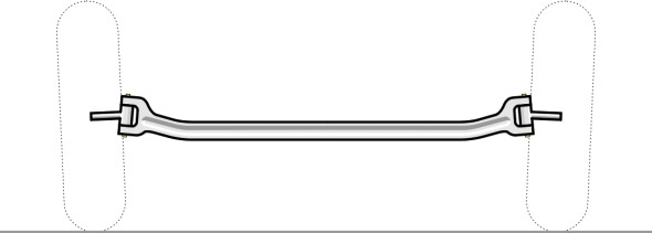
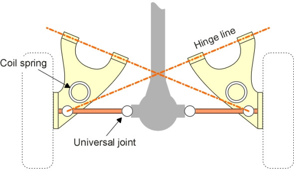
The main parts of a car suspension are the wheel, the wheel carrier or hub, the spring, the damper, and the mechanical linkage that connects the wheel hub to the car body. Figure 1 shows the components of a double wishbone assembly. Additionally, within the front suspension there must be a hinge around which the wheel pivots to provide steering. On early vehicles a kingpin was fixed to either end of the beam axle and each wheel hub pivoted around bearings on the corresponding kingpin (figure 2). Nowadays with independent front suspension, there is no kingpin as such. In the case of a double wishbone suspension for example, the wheel hub pivots around two ball joints. But the imaginary line joining them defines the axis of rotation, and this line is still referred to as the kingpin axis.
Figure 1
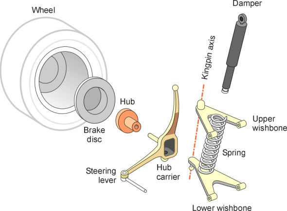
Figure 2
Most of the joints in a suspension system are slightly flexible, being cushioned with elastomer bearings that absorb shocks and therefore reduce wear as well as doing away with the need for regular lubrication. The relative movement at each joint increases roughly in proportion to the size of the load, and as it does so, dissipates energy through friction. It follows that the system as a whole behaves like a series of springs and dampers arranged in the form of a cascade. The process of dealing with road surface irregularities takes place at several different levels within this cascade.
The cascade
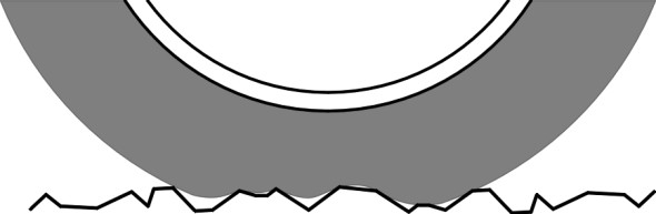
At the lowest level, the tyre acts as a stiff ‘spring’, absorbing high-frequency vibrations (between 20 and 400 Hz) that are associated with small-scale surface roughness. This roughness comes from individual stone particles embedded in the road surface, typically on a scale of just a few millimetres across. The tyres work mainly by wrapping the tread around the projections so that the road surface texture is effectively ‘averaged out’ (figure 3). The tyre is attached to the wheel, which itself is slightly springy and absorbs a certain amount of shock loading, as do the elastomer joints mentioned earlier. By contrast, low-frequency excitations of the order of 1 Hz are passed further up the chain to the suspension spring proper, working in parallel with the damper. Together they handle surface roughness that comes from potholes and other large-scale irregularities in the road surface level, typically hundreds of millimetres across and more. Occasionally, large impacts will carry the suspension towards the limit of its travel. It is therefore necessary to have supplementary springs that progressively stiffen the response at either end of the range. These are often mounted inside the damper. Finally, there may be ‘bump stops’ that are intended to prevent damage to the chassis, which can itself flex slightly, as of course can the passenger seats.
Figure 3
All these processes help to minimise the amount of energy that is passed up the chain before reaching the vehicle occupants, and they all work in more-or-less the same way. But they are not the only solution. One can also alleviate the impact by paring down the weight of the wheel and any components that bounce up and down with the wheel when it deflects over a bump – in other words reduce the unsprung mass.
Unsprung mass
We have already referred to unsprung mass in Section G1114. The impulse that is passed on to the car body by the wheel as it rises over a bump in the road depends to some extent on the mass of the wheel and the components linked directly to it. Consequently, a heavy wheel passes on a large impulse, some of which filters through the spring and damper to the car body. On the other hand, a light wheel passes on a less energetic impulse, and in particular, reduces the intensity of ‘wheel hop’ at around 10 Hz. And it stays in better contact with the road surface and therefore improves roadholding. There are two other reasons for reducing unsprung mass:
- A large unsprung mass increases the severity of impact between the wheels and the road, which in the case of heavy lorries, can damage the road surface.
- Unsprung components must withstand heavier road shocks than sprung ones, and must be relatively robust. This adds weight, which both increases the fuel consumption and increases manufacturing costs.
During the 1950s, the quest to reduce unsprung mass reached its peak, and luxury saloons were characterised by small wheels in relation to their size. It is still an important priority for light vehicles, and partly accounts for the introduction of alloy wheels on ‘sporty’ models. Nowadays the unsprung mass associated with one wheel of a moderately large saloon is typically around 45 kg (100 pounds) [5].
Figure 4
Nesting order
A good way to reduce unsprung mass is to do away with rigid axles that stretch across the vehicle body, and replace them with independent suspension. Another is to make the wheels lighter by making them smaller. Small wheels were once common on cars such as the BMC Mini, but their rolling resistance was high and the tyres wore out quickly. The trend nowadays is to retain the larger wheel size but to cast the wheel disc from a more sophisticated, lighter material such as aluminium or magnesium alloy. A more radical approach involves re-positioning suspension components higher up the cascade; for example, one can mount the brake discs inboard of the springs. Of course, moving components up the cascade is equivalent to moving the springs down. Carrying the notion to its logical conclusion, one can imagine the springs incorporated within the wheel disc so that only the rim and tyre are included within the unsprung mass. Early attempts to develop a ‘springy wheel’ for horse-drawn carriages failed, but a WW1 aircraft, the Linke-Hofmann RII, had steel wheels each of whose wooden tyres incorporated a multi-spiral spring [24].
Payload
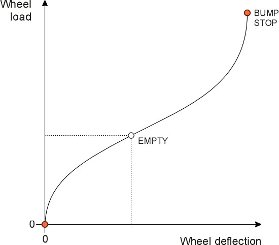
When fully loaded, a saloon car will carry a payload of passengers and luggage equivalent to about 40% of its unladen weight. As you may have noticed, in this condition your family car will ride more smoothly than it does with just the driver on board. This is because the greater static deflection reduces the natural frequency of the suspension springs (see equation 2 in Section G1115). The drawback is that the amount of spring travel available for soaking up road surface roughness decreases as the cars fills up with passengers, until the car is finally resting on its bump stops [12]. Ideally, therefore, to provide an equally smooth ride under all loading conditions, the stiffness of the springs should vary according to the number of passengers and the load carried. Most springs today are not ‘linear’ but ‘progressive’, in the sense that a progressively larger force increment is needed to produce a given deflection increment as the vehicle sinks further on its springs. As shown in figure 4, the slope of the load-deflection curve increases under load. For heavy trucks, where the payload can amount to several times the weight of the vehicle itself, the problem calls for a more radical approach, for example using air springs whose stiffness can be varied automatically to suit the loading conditions.
Suspension kinematics
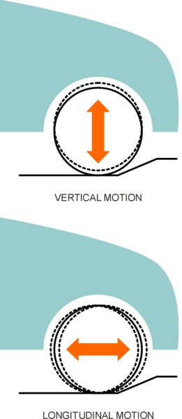
The purpose of a car suspension is to allow each wheel move freely up and down over bumps and potholes in the road. It would be nice if it allowed the wheel to move backwards and forwards as well (figure 5), because the impacts delivered by a rough road surface are not just vertical - they have a longitudinal component too. But from a mechanical point of view, longitudinal movement is difficult to cater for and it would interfere with braking and road-holding, so engineers compromise by putting cushions in the suspension joints that absorb some of the shocks. But to a first approximation, suspension systems on cars, trains and aircraft only move up and down, and in this sense, they only do half the job.
Figure 5
The problem of unwanted movements
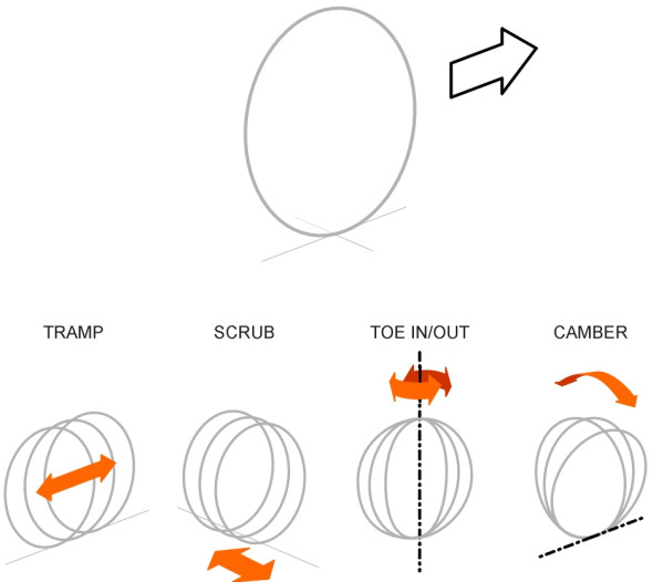
Assuming we can get the mechanism right, there is still the problem of distortion under load. Up to now, we have assumed that each wheel of the car is firmly fixed in place, unable to move in any direction except in the direction we want, i.e., up and down, and in the the case of the front wheels, additionally pivoting from left to right. Ideally, we want the wheel to remain in the same vertical plane throughout so that it doesn’t crab sideways, or swivel out of alignment, or tilt away from the vertical (figure 6). But none of the suspension components are entirely rigid; they all expand or contract fractionally when squeezed or stretched, and as explained earlier, elastomer cushions at the joints allow some relative movement. So on a real car, the suspension will deflect away from the reference position from time to time. Although the movements individually are quite small, their cumulative effects are not, and distortion under load affects the geometry of the system. For example, under the strain of heavy acceleration the front wheels of a well-known family saloon move forwards relative to the car body by a distance of around 14 mm. Similarly, they are dragged rearwards under heavy braking [21]. Without careful design of the suspension linkages, an axle can ‘tramp’ (oscillate repeatedly back and forth) when subjected to heavy torque.
Figure 6
Scrub
So what about lateral movements? They can occur with either front or rear suspension but for simplicity we’ll concentrate on the rear wheels. The distance between the centres of the two contact patches is called the track width. If the track width varies whenever the vehicle travels over a bump, the tyres will scrub the road laterally (figure 7). Such variation is not unusual. The track width of a family car can increase by 12 mm when the car is fully loaded, compared with the value when empty [22]. With certain types of suspension, continual jounce and rebound of the suspension while the car is in motion will quickly wear out the tyres, and on a curve, the lateral forces may interfere with directional stability.
Figure 7
Toe-out
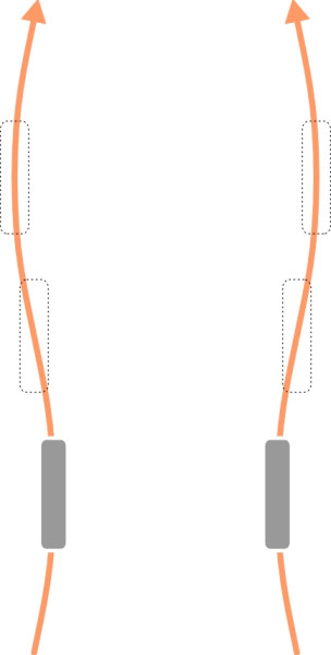
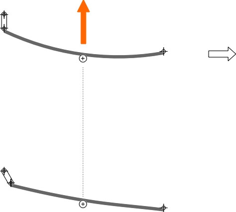
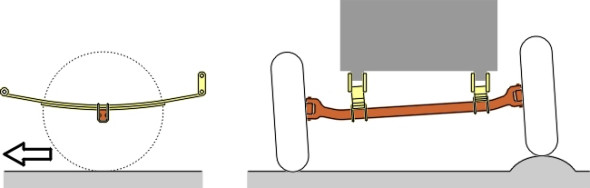
While lateral movements are a nuisance, swivelling movements are potentially dangerous. Any unintentional ‘toe-out’ in the plane of a rear wheel about its vertical axis will cause the vehicle to steer out of line. The effect is most severe when both wheels swivel in the same direction, a phenomenon that can arise when the vehicle body rolls outwards on corners. Roll-induced steering of this kind was quite common fifty years ago, when most cars were equipped with a rigid rear axle suspended on leaf springs, and this arrangement is still commonly found on light vans and trucks today. On a sharp curve, the body rolls, causing increased deflection on the ‘outside’ spring and reduced deflection on the ‘inside’ spring. When a leaf spring deflects, it flattens and therefore its horizontal length increases as shown in figure 8. The extra length is taken up by the shackle through which the trailing end of the spring is attached to the chassis. As a result, the axle attachment on the outside spring moves rearward. Conversely, the axle attachment on the inside spring moves forward. Hence the whole axle deviates out of line, effectively steering the vehicle more sharply into the curve (figure 9). As a result, the body roll intensifies, leading to increased axle deviation, and so on. The effect, as with any form of oversteer (see Section C0418), can be very disconcerting for the driver. Fortunately, the problem can be treated by mounting the rear end of the spring higher than the front (figure 10). Better still, if the springs are designed with less curvature, the system can be made to understeer [19].
Now for the front wheels. Early cars suffered from ‘shimmy’: rapid oscillations around the kingpin axis as if the driver were tugging the handwheel alternately left and right in quick succession [2] [15]. They arose at a certain critical speed and grew rapidly in magnitude until the driver slowed down, characteristics similar to those of ‘hunting’ in railway trains and ‘flutter’ in aircraft wings, of which more later. There were two main varieties, each with its own characteristic frequency, the higher one being associated with the gyroscopic properties of the spinning front wheels. The problem receded with the arrival of wider tyres, independent front suspension, and dampers attached to the steering mechanism.
Figure 8
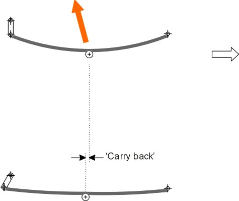
Figure 9
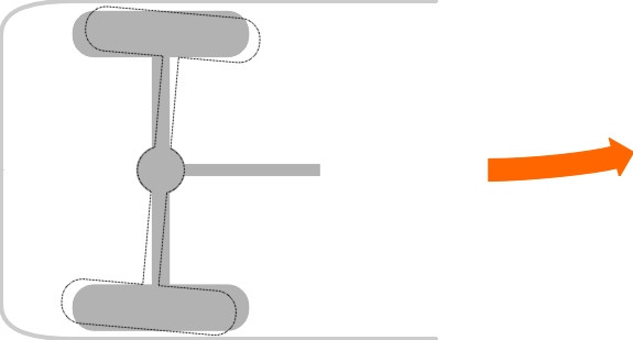
Figure 10
Camber change
Although shimmy has been eliminated, the gyroscopic forces can still cause difficulties. If a front wheel undergoes a sudden change of camber (leans away from the vertical) it tends to precess, twisting about a third axis mutually perpendicular to the axis of tilt and the plane of rotation. In the case of a motor vehicle, this axis happens to coincide roughly with the kingpin axis, so the wheel tends to steer out of line. This is a particular problem for beam axles because the canting of the axle as one wheel passes over a bump imposes a sudden change in the plane of rotation of not just one but two rapidly spinning wheels (figure 11). Hence, if one wheel passes over a bump or falls into a pothole, a car with a front beam axle will tend to veer to one side [14].
Figure 11
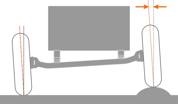
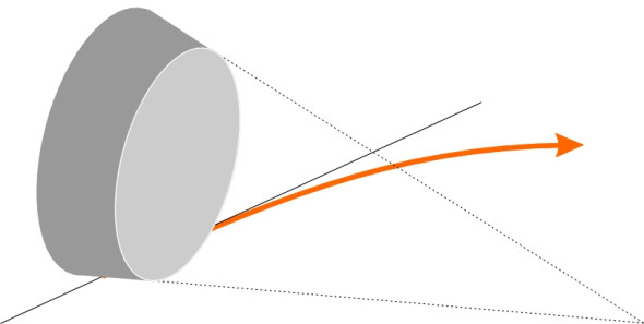
The problem does not arise with independent front suspension, where the camber angle for a car tyre at full wheel jounce rarely exceeds 4% [20]. Unfortunately, however, there is a different problem. When travelling on a curve, the body leans outwards, and as figure 12 shows, the wheels lean with it. This has two consequences. First, the tyre of a cambered wheel behaves like a cone with its vertex at road surface level (figure 13). Since a cone rolls naturally around its vertex, a wheel that leans to the right will steer to the right, and one that leans to the left will steer to the left. Second, the pressure distribution on the contact patch becomes lop-sided. This is particularly important for the wheel on the outside of the curve, which carries a greater load and is responsible for the greater part of the cornering force necessary to keep the car on the road. The inside edge of the tread can lift clear of the road surface, which reduces the area of the contact patch and therefore reduces grip. Both these effects are particularly noticeable with modern wide tyres, so with independent suspension it is vital to keep body roll to a minimum, and as described later, this is usually done by fitting an anti-roll bar to the front axle.
Figure 12
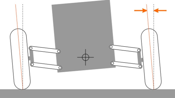
Figure 13
Suspension linkages
As mentioned earlier, we want each wheel of a car to be capable of up-and-down movement without any unwanted deviations from its static position. No mechanical linkage can actually meet this requirement, although several designs come close to doing so. Details can be found in many excellent publications (see for example [3] [6] [9] [11] [13] [18]). Here we shall concentrate on a few examples, using them to illustrate some practical aspects of suspension geometry.
Parallel and reciprocal motions
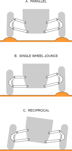
First, though, it’s necessary to point out that the behaviour of vehicle suspension cannot be understood entirely in terms of the behaviour of a single wheel moving in isolation. One must take into account what is happening to the wheel on the opposite side. We shall distinguish three conditions that occur when a vehicle moves over a rough road:
- The wheels go into jounce simultaneously, a condition sometimes referred to as ‘parallel springing’
- One wheel goes into jounce while the other remains unaffected, assuming that the vehicle body remains upright.
- Body roll (‘reciprocal springing’ [17]).
The last condition occurs when the car travels round a curve, forcing the outer wheel into jounce and the inner wheel into rebound. All three are shown in figure 14, and we shall refer to them again shortly.
Figure 14
Front suspension
Most early cars had rigid ‘beam axles’ and leaf springs (figure 15). Beam axles have the desirable property that they preserve the geometrical relationship between the two wheels: when one wheel goes over a bump (diagram B in figure 14), the track width remains constant so that the tyres do not ‘scrub’ the road surface laterally, which would accentuate tyre wear. On the other hand, the axle tilts, and gyroscopic precession gives the steering a kick. When cornering (diagram C figure 14), the wheels stay upright, which is good for grip.
Figure 15
Modern independent suspensions deal with precessional effects by (a) removing the connection between the front wheels (hence the origin of the term independent suspension), and (b) by providing a system of links that constrains each wheel to move up and down more-or-less within its own plane. Independent suspension also has the effect of reducing the unsprung mass, and in the case of passenger cars, by dispensing with a beam axle it allows more room for the engine to be positioned between the front wheels. The coil springs can be placed further apart, effectively at full track width as opposed to not much more than half the track width typical of leaf springs. This allows the use of softer springs without increasing body roll [7].
Figure 16
Of all the modern varieties of suspension, the transverse double wishbone (figure 1, figure 16) is nowadays regarded as state-of-the-art not only for passenger cars but for buses as well. There is scope for adapting to the needs of different vehicles by changing the lengths and the angles of the wishbone arms. If the upper wishbone is made shorter than the lower one, the outward lean of the wheel is reduced on corners, while at the same time, lateral scrub is minimised.
Figure 17
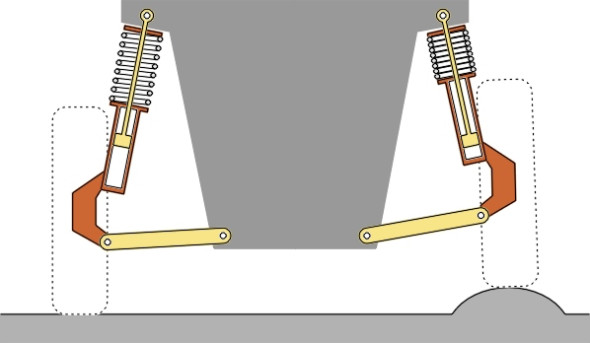
The MacPherson strut achieves a similar effect with fewer moving parts (figure 17). Used originally by Ford, and by many other automobile companies today, it is well suited to cars with transverse engines because the absence of an upper wishbone leaves more room at the level of the wheel centreline and above. Note that the MacPherson strut also requires a fore-aft link to locate the wheel firmly in the longitudinal direction, which is not shown in our diagram. An ingenious feature of the original design by Earle S MacPherson is that instead of pivoting on separate body mountings, the fore-aft links on either side are connected via a lateral bar to form an anti-roll bar – hence each link serves two purposes.
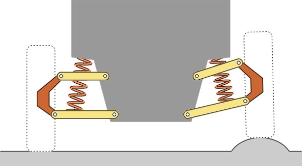
The anti-roll bar
All these types of suspension are shown reacting to a bump encountered by the left-hand front wheel. Both the double wishbone and MacPherson suspensions keep the wheel nearly upright and although there is some lateral track change, it isn’t very much. What the figures don’t show is the effect of roll on corners. Most cars lean or roll outwards on corners so that the passengers slide in their seats towards the outside of the curve. The old-fashioned beam axle is the only suspension that keeps the wheels both perpendicular to the road surface and at constant track while the body tilts. As already noted, with an independent suspension, if the whole car leans, the wheels lean with it, and this tends to lift the inside edge of the tyre clear of the road surface. And less contact means less grip.
Figure 18
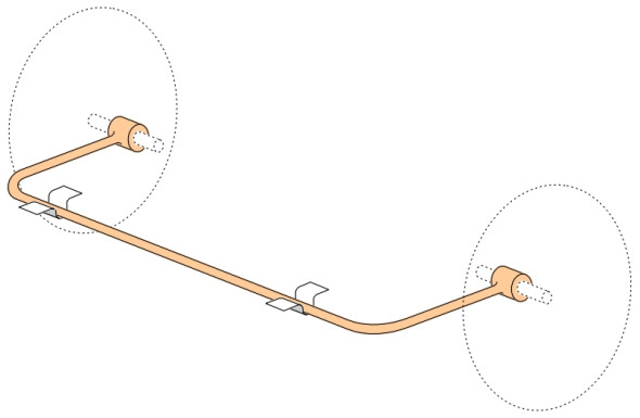
This why cars with independent front suspension almost always have an anti-roll bar, whose purpose is to limit the roll to an acceptable level (figure 18). It is not totally rigid, but flexes in torsion to allow some independent movement of the two front wheels. However, there is a drawback. If both wheels encounter a bump at the same time (diagram A in figure 14), the behaviour of the suspension is unaffected, whereas if only one of the two wheels is deflected by a bump (diagram B in figure 14), some of the impulse is passed through the torsion bar to the other wheel so that the impact is absorbed by two spring/damper units rather than one. Momentarily, the suspension is stiffer than it would otherwise have been, so its natural frequency rises and it becomes less effective at absorbing low frequency impacts that would otherwise have been the case.
Rear suspension
Manufacturers didn’t need much persuading to switch to independent suspension for the front axle, but the rear axle was a different matter. The ‘Hotchkiss’ layout with longitudinal prop shaft, beam axle and rear leaf springs persisted for many years, and variants of this layout are still used on light vans and trucks (figure 19). Independent rear suspension for cars was finally triggered by the widespread introduction of front-wheel drive, which removed the need for a continuous rear beam axle altogether. Today, most front-wheel drive cars use a simple trailing arm or a variation on the trailing arm principle for the rear suspension, while rear-wheel drive cars are equipped with semi-trailing arms (figure 20), double wishbones, or occasionally MacPherson struts.
Figure 19
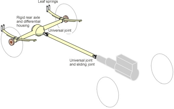
Figure 20
Postscript
Using one of the construction kits still sold in department stores, any bright child can make a toy vehicle that rolls smoothly along the kitchen floor. But it can’t easily be scaled up to passenger car size and run at passenger car speeds, because when you scale up a model the mass increases rapidly and so does the rate at which energy is fed into the vehicle from bumps in the running surface. The result can loosely be summed up as follows:
(1)
\[\begin{equation} \mathrm{mass} \; + \mathrm{energy} \; + \; \mathrm{springs} \quad = \quad \mathrm{vibration} \end{equation}\]Automobile pioneers discovered this early on with the suspension systems they had adapted from horse-drawn carriages. As speeds rose and cornering forces increased, although the springs were stiff enough to hold the axle more-or-less in place, they were prone to oscillate. As the vehicle accelerated, vibrations would be triggered off by road surface irregularities together with any imbalance in the front wheels. The steering became unpredictable, the front wheels tended to hop when the brakes were applied, and in some cases the front suspension would shimmy until either the driver slowed down or the car shook itself to pieces.
There were other problems too, but with the aid of mathematics (see Section G1115) and a great deal of trial-and-error, engineers solved them one by one. The next step, if and when it happens, will be to de-couple the car body from the road surface altogether, so the vehicle floats along smoothly regardless of bumps and potholes. Part of the challenge is that the damper undoes some of the work of the spring by resisting jounce and rebound: if it didn’t, passengers would be bouncing in their seats ad nauseam. But as a by-product, some of the input by-passes the springs and is fed directly into the car body. And of course the forces in the springs themselves vary from moment to moment with every impact from the road surface. It is this residual output from the spring and damper that makes travel less comfortable than it might be, and for many years, engineers have considered the possibility of an intelligent system whose output never varies. In principle, an intelligent suspension will anticipate road surface irregularities, lifting the wheel over each bump so that the load remains constant. While grip is thus maintained, no impact will be transmitted to the vehicle or, for that matter, to the road.
Making a system work along these lines is far from easy [16]. At the time of writing, systems have been implemented by several manufacturers, including Mercedes Benz, but they only react to low-frequency input. High-frequency input is handled by a conventional spring and damper system. In fact most engineers believe that a fully ‘active’ suspension will be too expensive for mass-produced cars for many years to come. One of the difficulties is fundamental: high frequency operation would require the actuator at each wheel to raise and lower an unsprung mass of 45 kg around twenty times per second. To get some idea of what this entails, lift your armchair and try shaking it up and down with your bare hands.
Loose ends
The suspension springs of the WW1 Linke-Hofmann biplane landing gear were built into the wheels. This reduced their unsprung weight. Would it be feasible to revive the concept, say, for off-road vehicles today?
Acknowledgement
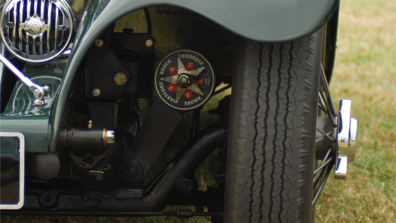
Photo on opening page: Jaguar front suspension by Joanna Walpole.