© Kiekhaefer Corporation
M.1718
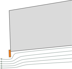
Planing craft
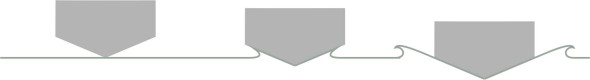
Centuries ago, boats were built to a standard pattern that scarcely changed from one generation to the next. The hull was long and narrow, with a pointed bow that sliced through the waves. We still build ships like this, mainly cargo ships and passenger cruisers, but they are slow, taking two weeks or thereabouts to cross the Pacific. The reason is that to move at all, they must push aside a large quantity of fluid. To make a ship go faster, one must somehow lift the hull out of the water, and a good way to do this is to slam the surface sufficiently hard to propel it downward. Water has significant inertia, and the force needed to deflect each particle of fluid creates an equal and opposite reaction that helps to support the vessel’s weight. You can see the effect in action when a swan lands on a lake. The swan lowers its feet at an angle, so they skate across the surface and thrust water particles aside sufficiently hard to balance the load until the bird slows down. Likewise, a boat with a nearly flat bottom will plane with most of its hull raised above the surface, supported by a relatively small area of its skin in contact with the water.
Figure 1
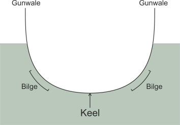
Figure 2
Skating across the surface
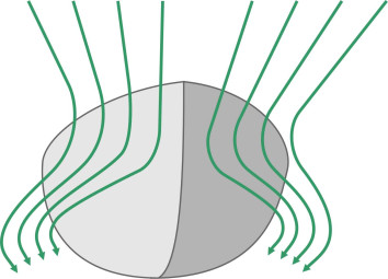
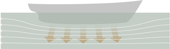
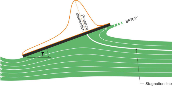
How do you make a boat ‘plane’? Surely it’s a matter of speed: if you can make it go fast enough it will behave like a swan landing on a lake. But a conventional hull is the wrong shape. When it moves forward, water piles up ahead of the bow, and because the hull is rounded in cross-section (figure 1), each water particle travels along a curved path around the bilge (figure 2). Also, fluid particles flow along the bottom and sweep upwards at the stern (figure 3). When you look at the streamlines from either direction, you can see they are squeezed together, and according to Bernoulli’s Principle, the water speeds up and the pressure falls. The result is shown in figure 4: the reduced pressure tends to suck the vessel downwards [21]. The effect is almost a mirror image of what happens when air flows over the body of a car, which tends to suck the vehicle upwards, away from the road surface. In normal circumstances, the downward suction on a ship’s hull is small, but if you try to increase the speed above a certain level, the hull will settle deeper into the water, particularly at the stern. You can get round this partly by making the hull long and narrow but as we’ll describe later in Section M1620, when driven hard it will create increasingly large bow waves that draw off energy. As a result, the ship will refuse to go faster, or at least it will need a lot of engine power to produce a small gain in speed.
Figure 3
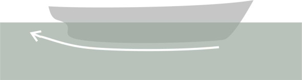
Figure 4
Features of a planing hull
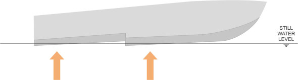
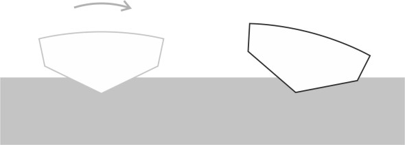
When a hull moves through the water, the motion of the fluid particles over its surface has two distinct components: a longitudinal component parallel to the keel, and a transverse component in which the particles are diverted outwards around either side. To make it plane, the designer must do three things. The first is to get rid of the curves: there must be no convex panels in contact with the water, so that the fluid does not speed up, lose pressure, and suck the hull down. Hence the curved profile is replaced by an assembly of flat panels that force the water particles to detach themselves both longitudinally and laterally. Let’s start with the longitudinal separation: viewing the hull from the side, we see a vertical panel at the stern known as a ‘dry transom’. At the lower edge of this panel, water particles shoot out from underneath the hull to leave a ‘hole’ in the vessel’s wake (figure 5).
Figure 5
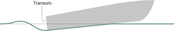
Figure 6
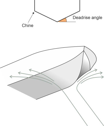
Now for the lateral separation: viewing the hull in cross-section, the traditional curved bilges are replaced by hard chines or kinks in the hull profile, which deter the water particles from clinging to the sides. Between the chines are two flat sections joined to form a ‘vee’ shape at the keel as shown in figure 6. Each panel is aligned at a shallow angle to the horizontal known as the deadrise angle. In order that the hull can cut through approaching waves, the vee is much sharper at the bow, but flattens progressively to a shallow vee or even a flat bottom at the stern. This means the two bottom panels are twisted or ‘skewed’: the overall effect is shown in figure 7.
Figure 7
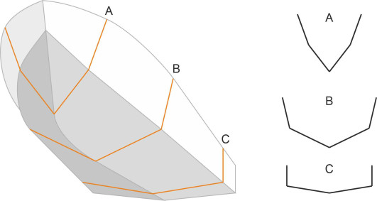
Figure 8
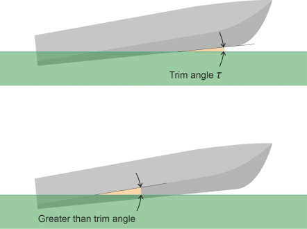
The second requirement is that the hull bottom should be angled so that on impact with the water surface, it displaces the fluid particles downwards (and as we’ll see shortly, some particles are displaced laterally and upwards as well). When viewed from the side, the angle is known as the angle of trim, here denoted by \(\tau\) (figure 8). Because the bottom panels are skewed, the angle at which they impact the water varies between the keel and the chines, and for practical purposes the angle of trim is measured at the keel. As long as it is positive the bow will remain higher than the stern and successive cross-sections will penetrate more deeply into the surface.
The third and final requirement is that in comparison with a conventional vessel, a planing vessel needs a great deal of power. There are several reasons for this:
- When accelerating from a standing start the boat must overcome a ‘resistance hump’ associated with downward suction on the stern.
- To maintain lift, it must travel faster than a conventional craft, and although the wetted area of hull surface is relatively small, it will face significant frictional resistance.
- There is an energy cost associated with dynamic lift that appears as an additional drag component, analogous to the induced drag generated by an aircraft wing (you’ll find a brief explanation of induced lift in Section F1816).
All this requires a powerful engine - strictly speaking, it is the ratio of power to weight that matters, because the lighter the vessel, the less water it displaces when at rest. A smaller displacement results in a reduced wetted area of skin and reduced friction both during the transition and while planing at maximum speed. Conversely, if you add weight, each additional kilogram reduces the maximum speed and carrying capacity of the vessel. Hence as well as a powerful engine the designer will call for lightweight (and more expensive) materials such as glass-reinforced plastics and welded aluminium.
In summary, one can see that planing vessels are capable of travelling fast, and moreover they must do so to work efficiently. To demonstrate how fast, it is helpful to work in terms of the dimensionless Froude number. Denoted by Fr, the Froude number plays a central role in ship dynamics and is explained in more detail in Section F1817 and also in Section M1620. It is calculated as follows:
(1)
\[\begin{equation} \text{Fr} \quad = \quad \frac{V}{\sqrt{gL}} \end{equation}\]where \(V\) is the speed and \(L\) the waterline length of the hull. The critical speed for planing generally coincides with a Froude number equal to 1.0 or thereabouts, and is therefore roughly equal to \(\sqrt{gL}\). For a vessel of length 50 m, with \(g\) set to 9.81 m/s2 this implies a planing speed of \(\sqrt{9.81\ \times 50}\), which comes to about 22 m/s or 43 knots. However, a boat can benefit from hydrodynamic lift at sub-critical speeds because the amount of lift becomes significant when Fr reaches 0.7 or 0.8 [13]. What might this mean for a fast passenger ferry? If we put
(2)
\[\begin{equation} \frac{V}{\sqrt{gL}} \quad = \quad 0.7 \end{equation}\]then for a vessel of waterline length 50 m the speed comes to \(0.7 \times \sqrt{9.81 \times 50} = 15.5 \text{m/s}\), or roughly 30 knots. Boats that operate at these intermediate speeds are referred to as ‘semi-displacement’ vessels. The criteria for the three main categories of vessel (displacement, semi-displacement, and planing) are summarised in Table 1. Note that the figures shown in the Table are approximate: the values for individual vessels vary according to hull shape, size and weight.
| Froude number Fr | Vessel type |
|---|---|
| Up to 0.4 | Displacement vessel |
| 0.4 - 1.0 or more | Semi-displacement vessel |
| Over 1.0 | Planing vessel |
How it creates lift
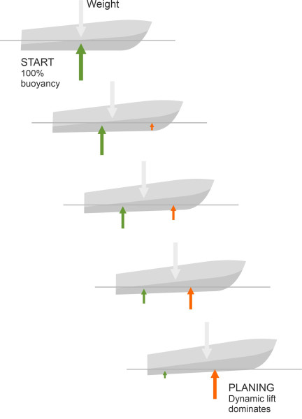
While a conventional displacement vessel pushes the water aside, a planing hull impacts the water surface to create lift. To be more accurate, a planing hull draws lift from two sources: partly from its buoyancy as would be the case with a conventional displacement vessel, and partly from the dynamic acceleration of the water particles as they collide with the hull surface. The balance between these two lift forces changes with the speed of the boat. Let’s see what happens when a planing craft accelerates from a standing start. Initially, the whole of the keel lies below the surface with the trim angle \(\tau\) approximately equal to zero (figure 9). When the boat begins to move, provided it is moving slowly the keel remains submerged and the hull is supported by buoyancy forces like an ordinary ship. But as the speed \(V\) increases, the hydrodynamic lift rises in proportion to \(V^2\). The centre of lift lies ahead of the centre of mass, so the bow rises and with it, the angle of trim. At the same time, the contribution from buoyancy diminishes and the centre of buoyancy moves aft. Finally, as the boat begins to plane, the trim angle levels off and only the rearward part of the hull remains below the water surface. The buoyancy force is now minimal and the hydrodynamic force takes over.
Figure 9
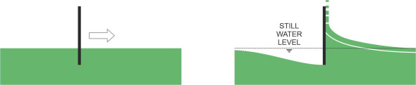
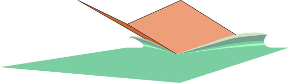
But where does the lift force come from? It’s tempting to imagine that the water is rammed downwards, in which case the planing action could easily be explained in terms of Newton’s Laws. But the process is not as simple as it appears. In order to find out what is going on, we’ll start by looking at an idealised form of hull, a flat plate like the upturned table pictured at the beginning of this Section, and we’ll picture its behaviour when held at different angles to the water surface, starting in an upright position with its lower edge immersed in the water as pictured in figure 10. Figure 11 shows the view from the side. The plate is then pushed through the water from left to right. As you would expect, some of the water passes underneath, but some of it piles up in front well above the undisturbed water surface to be ejected as a body of spray rising vertically in front of the plate (figure 11). The white line is the stagnation line: it marks the division between the two layers of fluid, and terminates at a stagnation point on the front face of the plate. When aligned vertically in this way, the plate doesn’t generate any lift but it does meet appreciable resistance from the water piled up in front: here, the fluid particles undergo abrupt deceleration in the longitudinal direction and it’s the reaction to this deceleration that leads to the high pressure on the plate. The pressure is not uniform but peaked, with the maximum at the stagnation point.
Figure 10
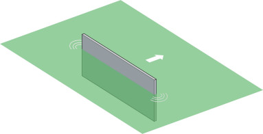
Figure 11
Now let’s see what happens if we tilt the plate forward as shown in figure 12. Although it makes a smaller angle \(\tau\) to the horizontal, notice that the water still piles up against the leading face, with the fluid above the stagnation line deflected diagonally upwards so the motion of the ejected spray has a distinct forward component. The bold white line represents the stagnation line, and since the place where it terminates on the front of the plate marks the region of highest pressure, you can see that the lift force is concentrated close to the leading edge of the wetted area.
Figure 12
The spray pattern in figure 12 seems puzzling – how can the water rise when the hull is pressing it downward? The explanation lies in how a fluid behaves close to a free surface when suddenly disturbed. The pressure in the water immediately below the plate acts in all directions, and the fluid particles closest to the plate follow the line of least resistance. Below the plate there is a large mass of fluid whose inertia resists any downward motion, while above there are only a few centimetres of fluid blocking the route to the atmosphere, and they can easily be lifted out of the way. The result is a jet of spray propelled upwards and forwards at a velocity relative to the plate roughly equal to the velocity of the plate itself. This distortion of the free water surface makes it harder to relate the lift force to what happens in the fluid beneath. Were we analysing the lift generated by an aircraft wing, we would be looking for a jet of fluid accelerated downwards – a ‘downwash’ that could be equated to the lift using Newton’s Second Law. Here, we can see there is a downward movement below the stagnation line, but the flow above the stagnation line is effectively transformed into ‘upwash’ at the water surface, and we can’t easily gauge the net effect. In principle, we could take tackle the problem in a different way altogether, by evaluating the lift force in terms of the energy lost in the fluid particles ejected above still water level (see [2] for how this can be done).
Figure 13
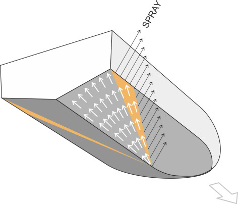
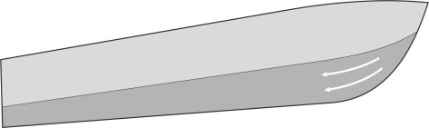
Now let’s look at a more realistic hull shape. Rather than a single flat plate, a planing hull can be more accurately represented as two flat plates joined at an angle as shown diagrammatically in figure 13. Although the geometry is more complicated, the same principles still apply. The water piles up in front, but it is also deflected to either side, and the spray is ejected in a lateral direction rather than forwards. So what happens underneath the hull? figure 14 shows how the fluid particles move predominantly in the longitudinal direction with a lateral component close to each chine. The highest pressures are concentrated in the V-shaped region highlighted in red; it is close to the leading edge of the wetted area. It is here where the fluid particles change direction that most of the lift is generated, and the high pressure creates a raised fluid ‘hump’ underneath the ejected spray.
Figure 14
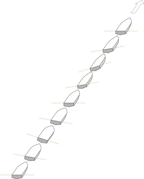
The behaviour of a planing craft is not easy to describe in terms of a mathematical model, but some analysts have tackled the problem by treating the hull as a falling wedge. Picture a block of water at a particular point in the path of the vessel, lying at right angles to the direction in which the boat is travelling (figure 15). We focus on this block before the vessel arrives then, ignoring its forward motion, watch what happens as successive cross-sections of the hull pass through the slice (this is rather like the method we used earlier in Section G1619 to visualise that effect of a wheel rolling along a road). The easiest case is to assume the hull is prismatic in form, meaning that the panels are not skewed and each cross-section takes the same shape with a constant deadrise angle throughout from bow to stern. As the bow cuts into the surface and successive cross-sections press more deeply into the water, the effect is like dropping a block with the same cross-section as the hull vertically into a container of stationary fluid. As shown in figure 16, the fluid that is intercepted by the hull moves out of the way; we know that there is a net downward deflection because the boat leaves a ‘hole’ in the water behind the transom, but some of the fluid accelerates outwards and upwards so that water is ejected on either side [8].
Figure 15
Figure 16
This simplified version of events has been modelled using potential flow theory to explain how the lift varies with the geometry of a prismatic hull [8], and based on pioneering work by researcher Daniel Savitsky for the US Navy [18], a number of empirical formulae have been produced over the years for estimating the lift and drag associated with a planing craft [8] [3] [14] [22]. The formula for lift takes the same overall form as the one used to predict the aerodynamic lift of an aircraft wing: the lift is proportional to (a) the area of wetted surface and (b) the square of the speed.
Trim
It has also been shown that for a boat travelling at a given speed, the lift is proportional to the tangent of the angle of trim \(\tau\) [8], or approximately proportional to \(\tau\) itself for small trim angles. In this sense, the angle \(\tau\) plays a similar role to the angle of attack \(\alpha\) of an aircraft wing, and to the ‘slip angle’ of a road vehicle tyre as detailed in Section C1717. If it’s too small there will be downwards suction so the hull cannot rise sufficiently out of the water to plane. If it’s too large the flow underneath will become more turbulent and create more resistance rather like the air flowing over an aircraft wing at a high angle of attack.
But the speed can be varied too – if more lift is needed, in principle one can install a bigger engine and use brute force to achieve lift-off. This raises an interesting question. The planing hull acts like a reaction motor, creating thrust by deflecting a stream of fluid. The question is how to do it efficiently, and here we have a choice: to put it crudely, we can deflect (a) a small amount of fluid through a large angle, or (b) a large amount through a small angle. To support a given load, in effect we have to juggle the size of the hull against the angle of trim. In the former case there is less friction because of the reduced wetted area, but more energy is lost within the fluid itself because more kinetic energy is injected into the fluid particles. It’s like the difference between a rocket and a helicopter rotor – there is much more wasted energy in the rocket exhaust than in the rotor slipstream, and in Section M1514 we’ll come across this issue again in connection with the wake of a ship’s propeller.
We are looking for an intermediate value of \(\tau\) that will produce adequate lift at the design cruising speed with minimal resistance, and for many high-speed planing craft the optimum is around 3 or 4 degrees. But the boat doesn’t know this and may settle at some other angle. There is a simple solution, albeit an expensive one: the designer can build a ‘step’ into the hull that effectively divides it into two separate units, one ahead of the other (figure 17) [23]. The effect is rather like adding a second wheel to a unicycle. It is hard to balance a vehicle that has only a single wheel, while two wheels in tandem provide a more stable platform. This is the method widely used for seaplanes, which rely on stepped floats to support them on water.
Figure 17
However, a stepped hull is complicated to build, and most boats don’t have one. Instead the designer relies on the hull geometry with the centre of mass and the thrust line of the propeller positioned so the vessel automatically settles at the desired angle. It’s partly a matter of balance. The trim angle is sensitive to the position of the centre of mass M, and while there isn’t a simple formula connecting the two, we know that for a boat to plane in equilibrium, M must lie behind the centre of dynamic pressure [21] and ahead of the centre of buoyancy as shown earlier in figure 9. Both of the lift forces exert couples about M, and the two couples must cancel each other out. In practice, M is usually located about two-thirds of the way along the hull.
Unstable motions
This raises another question. Imagine the boat moving at a steady speed in calm water. If the trim is disturbed slightly, perhaps by the impact of a wave, will it return to its previous angle – in other words, is the boat longitudinally stable? Common sense suggests that it ought to be: if the bow rises, both the hydrodynamic lift and the buoyancy force will move rearward, causing the hull to pitch forward again. The reverse occurs if the bow drops. In this sense, the trim of a planing hull is self-correcting. But we’ll see in a moment that if the bow drops too far, things can go wrong. And there are other problems that might arise with a fast-moving vessel. In particular, roll stability is in question because at speed, the hull rises mostly above the water surface. At this point, buoyancy forces that keep it upright when floating stationary in the water no longer work: there is no righting couple to restore equilibrium if a ship heels owing to a gust of wind for example [7]. So to stay upright, a planing vessel relies mainly on the dynamic pressures exerted by the water particles passing under the hull. If the hull shape isn’t right, it may be unstable at speed even in calm water. All these and other forms of instability have occurred in boats built during the last few decades, and although the motions are different, most have a single factor in common.
Root causes
The common factor is the curvature of the hull bottom near the bow (figure 18). Normally, this part of the hull rises out of the water when the boat is planing, and doesn’t greatly affect the boat’s behaviour. Fluid particles strike the hull some way aft, and they follow the hull surface until they reach the stern. Since the surface is nearly flat, their path is more-or-less a straight line. However, if for some reason the bow pitches down a little or intercepts a small wave, the situation changes. Particles collide with the hull close to the bow where the hull surface is curved, and their path follows this curve a little way until it straightens out under the middle section of the hull. The flow under the bow in some ways resembles the flow of air over an aircraft wing, except that the geometry is turned upside-down. The fluid speeds up and the pressure on the hull surface decreases so that in effect, the bow is sucked downwards into the water, which magnifies the original disturbance. Any disturbance that involves ‘positive feedback’ in this way can lead to problems, and it is this mechanism that seems to lie at the root of many forms of instability for planing craft [1].
Figure 18
The various forms of instability divide into two main classes: oscillatory and non-oscillatory. They are distinguished by what happens after the initial downward movement of the bow. If the forces change direction, the bow will rise again and the cycle will be repeated, leading to oscillations about a mean position. On the other hand, if the forces intensify, then theoretically the disturbance ‘diverges’, either growing until it reaches a new equilibrium or growing without limit until the vessel buries itself in the water and comes to a halt. Predicting the outcome is difficult, not least because the vessel’s behaviour may involve not just one motion such as pitching back and forth, but two or more motions that are dynamically ‘coupled’ – one motion influences another, and the second in turn reacts on the first. We have already met such a situation with railway trains in Section R0418: it takes place at the level of each individual axle as it moves along the track. The wheel treads have a conical profile, so if the axle shifts laterally to the right, say, by a small amount relative to the rails, the effective diameter of the right-hand wheel will rise. With each revolution, it travels slightly further than the left-hand wheel, and therefore the axle steers to the left. This eventually reverses the disparity in wheel diameters and the axle steers to the right again; thereafter the cycle is repeated indefinitely with the lateral displacement and yaw ‘coupled’. In the case of the planing vessel, the interaction of the hull with the water is more complicated: principal factors are the speed of the vessel, the shape of the hull, its weight in relation to the wetted area on which it is supported, and the relative positions of the centre of mass and the centre of pressure. To predict the vessel’s behaviour, you will need a sophisticated mathematical model, as described in [1] [4] [12], and [16]. Here we shall try to picture what is going on in everyday language.
Porpoise
The centre of lift for a planing vessel doesn’t remain in a fixed position – it fluctuates with the changing pattern of motion of the fluid particles under the hull. Imagine that the angle of trim is disturbed slightly, for example by a bird landing on the fore-deck. The extra weight will cause the bow to fall by a tiny amount. For some boats, the resulting decrease in trim angle will be magnified by suction under the fore-part of the hull, so the bow falls more sharply and the suction intensifies, and in fact when travelling above a certain speed, the boat will pitch sharply forward and settle into the water until it adopts a new position with increased drag and probably travelling at a reduced speed. The result is a significant change in both draft and trim, a form of divergent instability known as bow drop. It is often associated with heavily-loaded boats operating with a forward centre of mass and a low angle of trim [1] [17] [15].
Figure 19
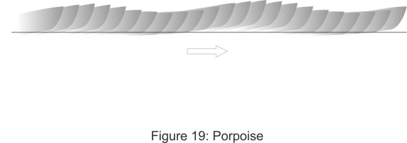
At higher speeds, the hydrodynamic forces operate differently and may trigger oscillations, especially if the vessel is running at a high angle of trim. It is liable to ‘porpoise’, pitching back and forth so that the bow alternately rises and crashes down on the water surface (figure 19). Oscillation can only occur if, after the intial bow-drop, the forces are reversed. It’s not immediately obvious why this might happen. The usual explanation is that when the bow drops, a greater length of chine is submerged under the fore-part of the hull. This tends to restore the hydrodynamic lift because the forepart of each panel strikes the water at a steeper angle than the aft part. Another possible explanation – an equally plausible one perhaps - is that the fluid particles are deflected laterally as well as downwards (figure 20), in which case they will follow a straighter path that generates less suction. Whatever the explanation, the bow will spring back up so the angle of trim rises again. And if the hull overshoots its original position the centre of lift H will continue to move aft. You can easily picture what happens next: since the hydrodynamic lift is proportional to the trim angle, the lift continues to increase as H moves rearward. This will rotate the hull so that it pitches forward again and the cycle repeats. Successive pitching motions can increase in amplitude fed by energy from resonant encounters with waves until the hull leaves the water entirely (figure 21). These effects are magnified in a rough sea, where the craft is exposed to destructive ‘slamming’ forces on the hull when it meets successive wave fronts. This is why, at speeds approaching 120 km/h in an offshore race [19], driving a light-weight racing boat can be dangerous. If the nose rises too far, aerodynamic forces can flip the craft over completely, and over the years, many occupants have been injured in this way. Possible cures include moving the centre of mass forwards, or, as we’ll describe later, fitting a control device of some kind [9] [15].
Figure 20
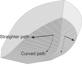
Figure 21
Chine walking
The second form of instability involves a different motion in which the hull rotates around a longitudinal axis rather than a lateral one – in other words it rolls. However the explanation follows the same pattern as before. The two halves of the hull bottom can be visualised as the upper surfaces of two inverted airfoils joined at an angle along the keel. Imagine a small disturbance in heel – perhaps a bird lands on the starboard gunwale. The resulting heel means that the starboard half of the hull sinks a little and more of the curved section near the bow becomes immersed. This creates reduced pressure under the starboard side which further exacerbates the imbalance [1]. As shown in figure 22, The heel can grow until the vessel reaches a new equilibrium position with the hull listing by as much as \(\pm 15^{\circ}\); the boat may continue in that attitude for some time until it slows down [9]. In appearance, the effect resembles the hydrostatic ‘loll’ that can occur with displacement vessels.
Figure 22
At higher speeds, some craft will heel repeatedly from side to side, a form of oscillation called ‘chine-walking’ [7]. The sequence of events is the same as the one that occurs during porpoising, except that the rise and fall of the hull occurs alternately on either side (figure 23). If, for example, the starboard side becomes more deeply immersed than the port side, the disparity is magnified by suction on the curved fore-part of the hull on that side, and the heel is magnified until the starboard chine bites sufficiently into the water to generate a counteracting lift. When the lift is restored, the vessel heels sharply towards the port side where the cycle begins again [17].
Figure 23
Corkscrew
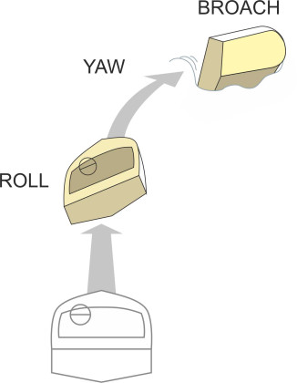
Our third and last form of instability involves coupled motion in roll and yaw. Like the others, it occurs in two forms. We’ll begin with the oscillatory form because it happens at a lower speed [10]. As before, the hydrodynamic forces acting on the fore-part of the hull will magnify a momentary heel disturbance until the hull has rotated through several degrees. But unlike the chine-walking motion discussed earlier, the heel gives rise to asymmetrical forces of a new kind: a heel to starboard causes the bow to yaw to port (figure 24) because the ‘down’ side of the hull generates a greater bow wave than tends to push it laterally towards the ‘high’ side [17]. Immediately afterwards, the angle of heel reverses and the bow yaws to starboard. The result is often called a ‘corkscrew’ oscillation (figure 25), and you’d imagine that the motion is very uncomfortable for passengers because the boat leans outwards - the wrong way – on each curve. It also puts the vessel itself in a precarious position. When travelling fast, vessels have been known to yaw violently and broach or even capsize (figure 26). It’s a form of diverging instability that happens quite suddenly in calm water with no obvious cause. Known as calm water broach, it’s a risk particularly for round-bilge hulls, making them dangerous to operate at Froude numbers over 1.2 [17].
Figure 24
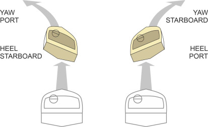
Figure 25
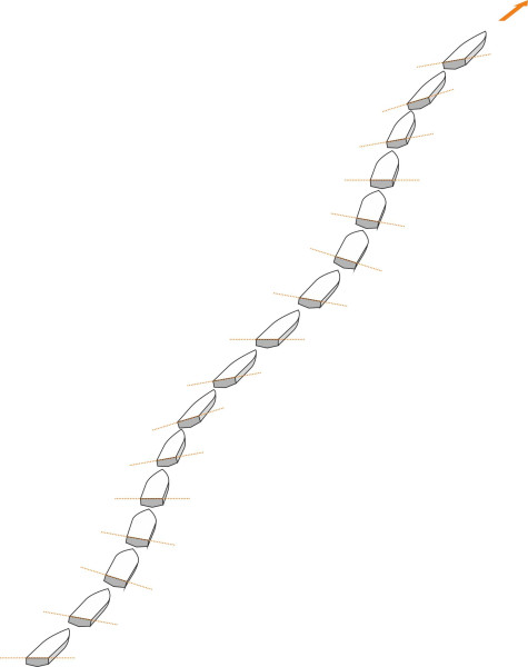
Figure 26
Control devices
A control device can be fitted to a high-speed craft to combat unstable behaviour. There are several alternatives; working automatically or semi-automatically, they alter the flow of water under the hull. Perhaps the most elaborate is an adjustable hydrofoil located at the bow. Simpler devices are located at the stern. They fall into two categories. The first is the trim tab: similar to an aileron on an aircraft wing, it is a flap hinged along the lower edge of the transom and controlled by a hydraulic actuator (figure 27). When the tab is lowered it provides extra lift at the stern, and when raised it has the opposite effect. If raised and lowered in time with the waves, it can reduce the intensity of pitching in rough water, and if the tab itself is split into two separate sections on either side of the centreline that can be raised and lowered independently, the device can help to control roll as well [6].
Figure 27
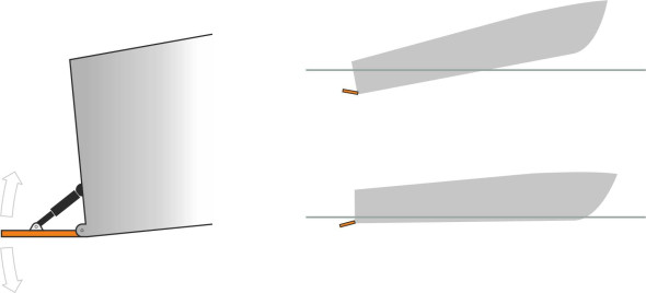
A simpler and more robust control device is the interceptor. An interceptor is an adjustable metal bar installed at right angles to the direction of motion across the hull at the bottom of the transom ([20] [6]. It can be lowered to project just a few centimetres vertically into the water where it interacts with the boundary layer, locally raising the water pressure on the hull and thereby reducing the trim angle (figure 28). Although it increases the drag locally at the stern, the effect is outweighed by an overall decrease in resistance associated with the extra lift – one of the rare instances in fluid mechanics where a rough or jagged surface generates less drag than a smooth or streamlined one.
Figure 28
Other ways to skate ...
You’ll have gathered that in a rough sea, a planing craft doesn’t give its passengers a comfortable ride, and in fact, the pilot will reduce speed when the waves reach a certain height. But planing isn’t the only way to achieve lift. Instead you can attach hydrofoils to the underside of a boat that ‘fly’ through the water and provide lift in the same way as the wings of an aircraft. Because water is much denser than air, they can generate considerable lift per unit area, and they’re less sensitive to wave action. A third way is to create a pressurised cushion that separates the hull from the water surface. In the two Sections that follow, we’ll examine hydrofoil craft and air cushion vehicles as alternative forms of high-speed water transport.
Acknowledgement
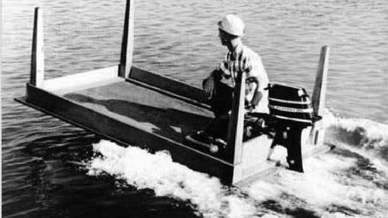
Photo on leading page: Kiekhaefer Corporation, advertisement for Mercury Outboard motors, 1964 ‘Give me the right power and I can plane a kitchen table’.