M.0415
Manoeuvres
When you walk down the street, you are in control of a vehicle. The vehicle is your body, and although it’s a complicated machine, it’s easy to steer. You don’t need to trace out a smooth geometrical path, and in fact you’ll zig-zag a little from side to side. It’s an unconscious process. Your mind and body act as a feedback loop in which your mind receives warning signals that you are going off-course, and the signals trigger an almost instant response so you don’t have to plan each step in advance. Riding a bicycle or driving a car is much the same, but sailing a ship is different. Imagine you are the master of a cargo ship that weighs maybe 100 000 tonnes. You can’t drive it like a car, because everything works in slow motion – there are delays built into the feedback loop so the effect of any action you take doesn’t become apparent for some time. In this Section, we’ll look into some of the manoeuvres a ship might perform during a voyage, and see how steering and engine commands are strung together to make the vessel do what the master intends.
Controlling the ship’s course
The problem lies partly in the ship’s inertia, and partly in its physical size. A cargo ship may take a minute or more to turn through an angle of \(20^{\circ}\) [17], and since it has no brakes, a ‘crash stop’ will take much longer. Time lags of this order complicate the task of navigation in two ways. First, the master has to predict the ship’s motion and decide how best to handle the situation several minutes in advance. Second, whatever action the master decides, the ship will take time to respond. On the other hand, there are no kerbs or road markings at sea, so the master can request a straight course and change direction only when the need arises. In fact, turns are best avoided, for three reasons. The first is almost trivial: a straight course represents the shortest route and is much easier for the helmsman to steer. Second, a straight course is safer: if vessel A sights vessel B in the distance, and neither changes course for a while, the master of each vessel can work out where the other is likely to be in a few minutes’ time and keep out of its way. Finally, a curved path generates extra drag that slows the ship down. So a ship’s voyage can conveniently be broken down into a number of straight-line segments between consecutive ‘waypoints’. It changes course only at the waypoints, which are often planned in advance.
How to sail in a straight line
In order to sail in a straight line, common sense suggests that you steer straight ahead with the rudder in its central position until you get to the next waypoint. But the ship’s course will be disturbed by winds and currents, and a ship with a single propeller will naturally veer to port, so in practice a helmsman will use the ship’s compass as a guide, making corrections from time to time to keep the vessel pointing in the right direction. It’s how sailors have navigated for centuries, and it’s called sailing along a rhumb line (the term ‘rhumb’ comes from a sixteenth century Spanish word for compass point).
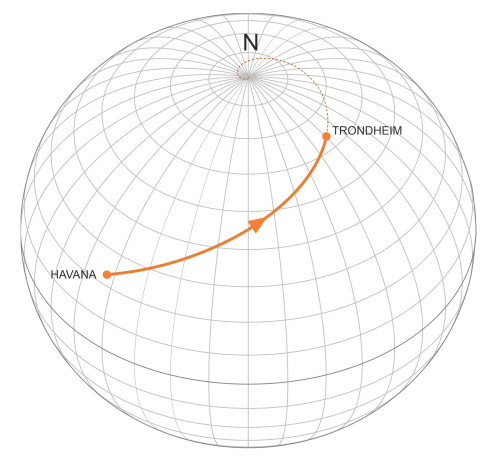
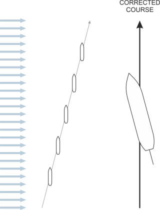
But it’s not actually a straight line. The reason has to do with the earth’s curvature. When we stand on a cliff at look out to sea, we think of the water surface essentially as a flat plane that extends without limit in every direction. But it’s not. The earth is spherical in shape, and the mean water level curves downwards towards the horizon, dropping by nearly 8 cm over the first kilometer. Viewed from a single vantage point, the curvature is miniscule, but over a long voyage, the consequences are significant: given that the helmsman maintains a fixed compass heading, the ship’s path will curve to one side. An example is shown in figure 1, which represents a vessel sailing across the North Atlantic from Havana in Cuba to Trondheim on the west coast of Norway. Throughout the voyage, the ship maintains a fixed compass heading of 57 degrees and 25 minutes east, in other words it has a fixed azimuth \(\alpha\) of \(57^{\circ} \ 25^{\prime}\). Although it crosses all the meridians at the same angle, the meridians themselves are not parallel, so the ship’s path is curved, and in fact to hold the compass heading steady, the helmsman must steer very slightly to port, increasingly so as the voyage proceeds.
Figure 1
Curiously, if the ship were to continue beyond Trondheim on the same compass heading, were it able to travel across the polar ice cap it would eventually arrive at the north pole. In fact, this is the case for any rhumb line route that has a northerly component with \(\alpha\) lying in the range between \(-90^{\circ}\) and \(+90^{\circ}\). If it has a southerly component the ship will head for the south pole instead. Either way, if we imagine the planet covered entirely in water, each pole represents a mathematical singularity from which the approaching vessel cannot escape. As it edges closer, in theory it will spiral around the pole at an angular velocity that rises to infinity within the last few moments of the journey.
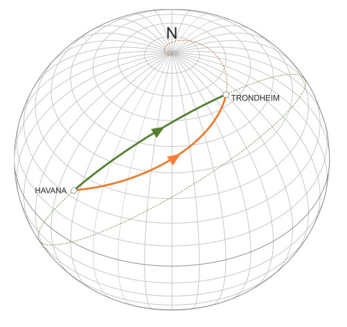
The rhumb line, of course, is not the shortest route. For most voyages this doesn’t matter because the extra distance travelled is quite small, and in practice, seafarers plan their routes to take advantage of favourable currents and winds rather than trying to minimise the journey distance as such. Nevertheless, let’s look at the geometry: the shortest route is part of the circle that passes through the trip origin and destination so as to bisect the globe. It is known as the great circle route, a term that you’ve probably come across at school. In figure 2 we see the great circle route that connects Havana with Trondheim. The ship doesn’t deviate to port or to starboard, so in principle, the helmsman’s task is simple – to steer straight ahead. But the compass heading changes continuously throughout, as you can see from the angle at which the route crosses successive meridian lines. And if the line of the route is projected beyond the ship’s destination, it passes around the globe to return to the starting point at Havana. For comparison, the great circle route and the rhumb line are shown together in figure 3.
Figure 2
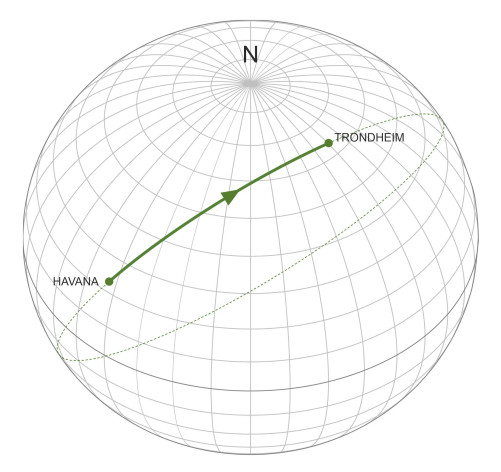
Figure 3
Course keeping
So how does one navigate along a great circle? A short journey can be treated as a single rhumb-line segment, in which case the helmsman can maintain a fixed heading from start to finish. A longer voyage will normally be divided into a number of rhumb-line segments that approximate the line of the great circle route.
Along any particular rhumb line, the helmsman will steer using the ship’s compass. A large vessel will have a gyro compass installed on the bridge in front of the steering position. Its flywheel assembly is free to rotate under a glass dome, and it carries a graduated disk from which the helmsman can read off the ship’s heading in degrees against a fixed pointer (figure 4). The idea is to maintain the present heading as accurately as possible until the next course change. When the ship is under manual control, the helmsman will spend most of the time watching the compass and making small adjustments to the wheel to keep the deviations within acceptable bounds. It’s easier to manage if the ship has an autopilot system that can be set to maintain a given heading, and this takes a great deal of pressure off the crew. However, the ‘heading’ that it measures is the direction in which the ship is pointing, which is not the same thing as the direction of travel. The direction of travel is influenced by the wind and current. A current may carry the ship off-course: it won’t cause the vessel to turn or veer onto a new heading, but rather to drift sideways, so the helmsman will need to compensate by steering a little upstream as described in Section F0505. However, the wind is trickier because it can affect the ship in two ways; like a current, it can make it drift sideways, but it can also rotate the ship onto a new heading. In principle, there are three distinct cases:
- Wind directly ahead or directly astern: the aerodynamic drag will affect the ship’s speed but not the steering.
- Wind on the beam: if the wind arrives at right-angles to the ship’s direction of motion, it will push the vessel to one side, so as shown in figure 5, the helmsman will need to adjust the heading to take into accounting the resulting leeway.
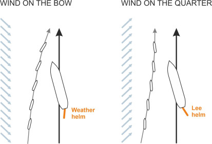
- Wind in any other direction: In all other cases the wind will not only push the vessel sideways but also cause it to turn and ‘run across the wind’ [8].
Figure 4
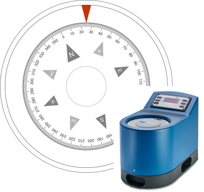
Figure 5
Case III calls for a little explanation: as one would expect, the wind exerts a ‘Munk moment’ on the hull and superstructure, tending to swing the bow round until the ship lies at right-angles to the oncoming air flow as explained in Section F1816. The outcome depends on the angle of the wind relative to the ship’s longitudinal axis. If the wind is ‘on the bow’, meaning it arrives at less than \(90^{\circ}\) from the bow as shown on the left-hand side of figure 6, the ship turns away from the wind and the helmsman must steer into it, in nautical terms, apply ‘weather helm’ and hold it there to prevent the ship from swinging off-course. On the other hand, if the wind is ‘on the quarter’, meaning that it arrives at less than \(90^{\circ}\) from the stern as shown in figure 6, the ship will turn towards the side that the wind is coming from, and the helmsman must steer to the opposite side, or in nautical terms, apply ‘lee helm’.
Figure 6
Nowadays, a course of this kind can be handled by a computer, and many large ships are equipped with a global positioning system (GPS) linked to a Tracking Control System (TCS) that executes the necessary rudder commands on the master’s behalf. The regulatory authorities are keen to point out that this doesn’t absolve the bridge team from maintaining a thorough look-out at all times, and when traffic is heavy or the visibility is poor, the crew must be able to switch to manual control in less than 30 seconds.
Executing a turn
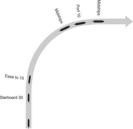
By now you’ll have gathered that ships move in a slow and stately fashion: travelling at a cruising speed of 20 knots, it will take a 400-m long passenger liner over half-a-minute to travel one ship length. And its rate of turn is glacial, as though time were standing still. This is partly because of its size and partly because of its inertia. In order to rotate around the pivot point, the various parts of the hull and its cargo must acquire momentum. And once the ship is turning, it keeps turning until the kinetic energy stored in the rotating mass is absorbed into the surrounding water, or until you apply a corrective couple by laying the rudder over to the opposite side. It follows that to execute a turn, the officer of the watch must start the rotation early and begin to slow it down before the vessel’s heading reaches the desired direction. The series of adjustments follows a standard pattern, and it is fascinating to see how the commands were passed from the master to the helmsman on a WWII warship. You can watch the sequence as portrayed in a historical training film for naval cadets in the British Royal Navy [19], in which the phrasing is clear, clipped and concise. We’ll re-work the procedure as it might have been applied to a right-angled turn. Imagine the ship is travelling due north on a heading of \(0^{\circ}\) and the officer wants to turn east, so the target heading is \(90^{\circ}\). The first command is:
‘Starboard 30’
This means ‘turn the wheel until the rudder lies at an angle of \(30^{\circ}\) on the starboard side’. It starts the rotation. After the rotation is under way, the rate of yaw continues to increase and the ship experiences significant drag. The officer can save fuel by easing the rate of turn. The next command is
‘Ease to 15’
meaning ‘reduce the rudder angle down to \(15^{\circ}\)’. After the ship has travelled along a curve of more-or-less constant radius for a few seconds, it becomes clear that the rotation should be halted otherwise the ship will overshoot the required heading. The officer calls
‘Midships’
following which the helmsman centres the rudder and waits for the next instruction. The officer calls
‘Port 10’
at which point the helmsman swings the rudder over to the port side to check the swing. If the officer has judged the timing correctly, the yaw rate will fall to zero just as the ship reaches its intended heading of \(90^{\circ}\), when the officer calls:
‘Midships’.
The various steps are illustrated in figure 7. Today, turns are carried out in essentially the same way, although the process is less formal, and minor adjustments are left to the helmsman. Alternatively, they can be carried out by an autopilot under computer control. Note that when taking action to avoid a collision, making a turn with the rudder hard over serves an additional purpose: it can reduce the vessel’s forward speed by as much as \(40\%\) [5].
Figure 7
Control at low speed
A ship will turn more quickly if it is moving fast, because the lateral thrust generated by the rudder rises as the square of the speed at which the water flows over its surface, so at high speed, the helmsman has more precise control. But manoeuvring at low speed is difficult, for two reasons. First, the vessel will turn in a smaller space, but it will take longer and the steering response will be less predictable. Second, some vessels can’t travel slowly unless the master repeatedly stops and starts the engines, and this is why controllable pitch props are often preferred to conventional ones: they can be feathered to produced a very small thrust at more-or-less constant engine rpm.
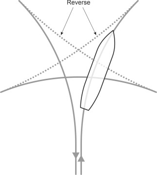
So how does one turn safely at a low speed? The force that makes the ship swing round is the sideways thrust of the propeller slipstream being deflected by the rudder. Without that slipstream, nothing will happen. So the best procedure is to ‘give a strong burst on the engines to commence the swing’ and then reduce the power [2]. Even a stationary vessel can change direction in this way, but to execute a \(180^{\circ}\) turn in a small space it will need to go forwards and backwards several times as shown in figure 8, like a car turning round in a car park [11]. In this fashion, a ship can be turned round in little more than its own length, and if the turn is made clockwise, the paddlewheel effect will speed up the process on each reverse leg (the paddlewheel effect is described in Section M1410).
Figure 8
Emergency manoeuvres
Readers will be aware of events happening at sea that call for prompt action from the crew, for example, the unexpected appearance of an obstruction in the ship’s path, a passenger or crew member falling overboard, or a close encounter with another vessel. With experience, mariners learn a repertoire of manoeuvres that might be needed in such cases. Let’s take the last one first. In a busy seaway, it often happens that a ship meets another vessel crossing its path. The master will judge its speed and direction of travel, and whether there is any possibility of a collision. The master of the other ship will do the same. Each will decide on a course of action, and try to anticipate what the other will do. Mistakes are not unknown: for example in January 2018 a cargo vessel collided with the oil tanker Sanchi off the coast of China, and none of the 32 passengers and crew travelling on the tanker survived. The greatest ever loss of passengers in a single accident – over 4 000 – occurred in a busy sea-lane near the Philippines in 1987, when the ferry Doña Paz collided with an oil tanker [18]. During the summer of 2017, collisions between destroyers led to an ‘operational pause’ that brought the whole of the US Navy to a halt.
Avoiding a collision
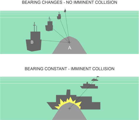
Imagine you are the master of a ship and you see another vessel approaching. Call your vessel ‘ship A’ and the second vessel ‘ship B’. How do you know the two ships are on a collision course? To find out, you can hold a steady course and take bearings of ship B at frequent intervals (the safety experts recommend not more than 3 minutes apart). Your compass has a sighting ring: when aligned with the ‘target’ you can read off the angle. As shown in figure 9, if it doesn’t appreciably change over time then the ships must collide unless one or both take evasive action. In this situation, a ship’s master has essentially four options: (a) to continue on his or her existing course and speed, (b) turn to starboard, (c) turn to port, or (d) slow down by putting the engines into reverse. In practice, a ‘crash stop’ is a last resort: when cruising at speed, the best way to avoid hitting something is to steer round it, because a ship can change course more quickly than it can stop, and within a much shorter distance.
Figure 9
The International Maritime Organisation (IMO) has formulated a set of rules that in principle guarantee a safe outcome. They evolved from rules originally formulated in Britain in 1862, and are set out in the International Regulations for Preventing Collisions at Sea 1972, popularly known as the ‘COLREGS’. You can find them reproduced in many books on sailing, for example [14], and we won’t reproduce them here. Instead, we’ll concentrate on the underlying principles and try to express them in diagrammatic form.
The rules assume two conditions: firstly, that both officers are aware that their vessels are set to collide, and secondly, that each understands the other’s intentions. So it’s important that each sends a signal making it clear what he or she proposes to do. They can communicate, for example, via the ship’s horns supplemented by flashing lights at night. These are some of the most commonly used signals:
- One short blast: I am altering course to starboard
- Two short blasts: I am altering course to port
- Three short blasts: I am switching to astern propulsion
As for the rules themselves, they are based on the long-established principle that if two vessels are steaming towards each other on potentially conflicting paths, both should turn to starboard and pass ‘port-to-port’ (figure 10). This is consistent with the rule that applies on land, which is that throughout most of the world, vehicles drive on the right-hand side of the road. At sea, knowing that the other vessel will turn to starboard, not to port, greatly simplifies the situation for both crews.
Figure 10
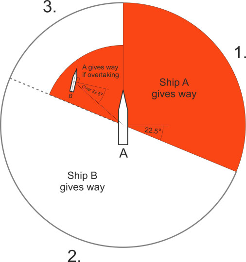
The port-to-port rule works when the two ships are approaching from opposite directions, but otherwise the situation is more complicated. Normally, one of them should give way, while the other ‘stands on’, meaning that it continues on its existing course. The question of which vessel should give way depends on the angle at which their paths cross and their relative speeds. The different situations are shown diagrammatically in plan view in figure 11. We are looking at a moving frame of reference centred on ship A, which is travelling along a straight course aligned vertically up your screen. The water surrounding ship A is represented by a circle that is divided into three sectors numbered 1, 2, and 3. Ship B can be located in any one of these sectors. It is approaching along a radial line that passes through A – the bow of ship B is not necessarily pointing towards A, but the vessel’s current path crosses A’s path and its speed and course are such that the two will arrive at the crossing point at the same time.
Situations in which ship A is expected to give way are shaded in red. The core rule is that it must do so if vessel B arrives on its starboard side, otherwise ship B gives way. However, there are exceptions to this rule. They are essentially overtaking manoeuvres, in which the faster vessel is catching up the the slower one from a direction that lies more than \(22.5^{\circ}\) abaft of the other’s beam (the angle \(22.5^{\circ}\) is equivalent to two compass points). In this situation, irrespective of whether it is arriving on the port or starboard side, there is an overriding requirement for the faster vessel to give way – it must not risk cutting across the other’s bow. The upshot is that if B arrives in sector 1, ship A gives way. If it arrives in sector 2, ship B gives way. If it arrives in sector 3, ship B gives way unless it is being overtaken, in which case ship A gives way.
Figure 11
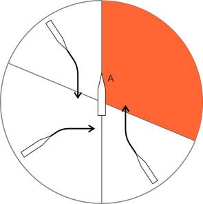
The rules appear to be framed so that when required to do so, ship B can give way by making a relatively shallow turn to starboard (figure 12). The same applies to ship A when the roles are reversed, with B at the centre of the circle. Any other arrangement would result in cases where the ‘give way’ vessel must turn through more than ninety degrees, which requires more room and allows less time for the master to act, thus increasing the risk of a collision.
Figure 12
It is possible to express the collision rules more concisely, in the form of a graph. First, we must define two angles: the bearing \(\theta_A\) of ship A relative to the direction of motion of ship B, and the bearing \(\theta_B\) of ship B relative to the direction of motion of ship A. As shown in figure 13, both angles are measured clockwise from the forward projection of the ship’s longitudinal axis. Figure 14 shows all the possible combinations of \(\theta_A\) and \(\theta_B\) shaded in colour. The red areas represent cases where ship A is expected to give way, while the grey areas represent cases where ship B is expected to give way. The graph is not intended as an alternative statement of the IMO collision regulations, which are set out in written form using terms and concepts familiar to experienced mariners. Apart from anything else, it is not a complete picture, because different rules apply in poor visibility, and they vary according to the types of vessel involved. The IMO regulations also detail the responsibilities of the parties concerned in a way that a graph cannot - for example, the master of the ‘stand on’ vessel is expected to monitor the situation and prepare to take emergency action if the other vessel does not conform to the normal procedure.
Figure 13
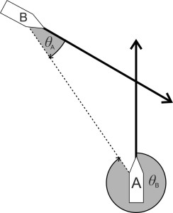
Figure 14
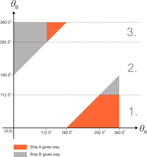
But the diagram throws light on the underlying logic inasmuch as it confirms that the ‘give-way’ rules apply in a consistent and symmetrical way to both vessels, and highlights those situations in which misunderstandings are most likely to arise. A critical area occurs around the origin, where \(\theta_A\) and \(\theta_B\) are both numerically small; the written regulations explain how the masters should handle such cases. Critical cases also occur on the boundaries between the red and grey areas, where one of the masters is required in effect to judge the heading of the other vessel. In principle, it should be possible for the two vessels to exchange information so the priority issue could be determined independently via a central computer linked via satellite communications to both vessels. This may not be too far off, and furthermore, research is now taking place on the application of artificial intelligence not just to collision avoidance, but to the wider problem of autonomous ship control.
Person overboard
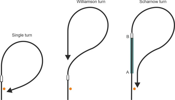
A cruise ship carries hundreds of passengers, and during a voyage, there is a chance that one of them will fall overboard. A crew member can also fall overboard while on deck duty, and this applies not just to a cruise ship but to a vessel of any kind. There are no official figures, but a search on the internet reveals that such incidents are not as rare as you might think: every month, several people go overboard, and less than a third of them survive. In this situation, prompt action is crucial, so what sequence of manoeuvres will reduce the delay and improve the chances of a successful rescue? There are three alternatives, all of which are shown in figure 15 for comparison.
- The single turn delivers the ship to the casualty more quickly than the other methods but the crew must be able to see the casualty throughout. After receiving the alarm, the helmsman lays the rudder hard over towards the side where the casualty lies in the water so that the vessel turns through an angle of about \(250^{\circ}\), nearly three-quarters of a circle, before stopping at an angle to its initial course to attempt a pick-up [12].
- The Williamson turn is the slowest of the three but it puts the ship in the best position to search for the casualty if contact has been lost. The helmsman lays the rudder hard over towards the side where the casualty is thought to have gone overboard, but this time turns through an angle of only \(60^{\circ}\) before switching hard over to the opposite side to circle round within \(20^{\circ}\) of the ship’s original course, where the rudder is centred to steady the yaw so the ship can make a search along its own wake [12].
- The Scharnow turn is used only when a person is reported as missing, and may have been in the water for some time. The ship turns and continues around nearly three-quarters of a circle until about \(240^{\circ}\) from its original course; the helmsman then lays the rudder hard over to the opposite side until the ship’s heading is \(20^{\circ}\) from the reciprocal course, when the rudder is returned amidships to steady the yaw so the ship can back-track along its wake. The turn-around takes less time than it does with the Williamson turn, but if the casualty is located anywhere within the section marked AB, he or she may not be spotted and the rescue will fail [12].
Figure 15
The crash stop
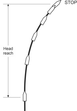
Now we can look at the third and last manoeuvre, which is essentially an emergency stop. The aim is to minimise the distance travelled before the ship comes to a halt. There is a specific test for measuring this distance called the ‘crash astern’ test [4]. It begins with the vessel travelling along a straight course at cruising speed. The master then calls for engines ‘full astern’. The engines are put into reverse (or the propeller blades are reversed if they are of the controllable pitch type). This may take some time depending on the type of engine and transmission. Turbine engines can’t operate in reverse, and instead the vessel will use auxiliary engines whose sole task is to propel the vessel astern – they may develop less than half the power of the main engines. In either case, reverse thrust makes control unpredictable and the ship is unlikely to follow a straight course. So during the test, its trajectory is plotted until it stops: figure 16 shows a hypothetical example. The forward component of the distance travelled after the full astern command is called the head reach. IMO regulations stipulate that the track reach, which is the stopping distance measured along the trajectory, should be less than \(15 l_{pp}\) where \(l_{pp}\) is the distance between perpendiculars [7]. Given that a car takes more than 20 lengths to stop when travelling at motorway speed, this might seem an ambitious target - until you realise that for a 400m-long oil tanker, the IMO stopping distance comes to \(15 \times 400 = 6\) kilometres. And the process takes between 10 and 20 minutes [3].
Figure 16
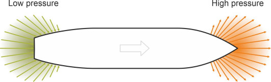
Moving in a confined space
As mentioned earlier in Section M1620, the ship’s bow acts like a moving ‘pressure point’ that pushes water aside, while the stern is a negative pressure point that sucks water in. Hence the pressure around the bow rises above the static pressure as shown schematically in figure 17, while that around the stern falls. When the hull moves forward in open water the pressure variations along either side are symmetrical and don’t affect the ship’s steering. But if the vessel passes close to a harbour wall for example, the pressure distribution becomes asymmetrical and will upset the balance of lateral forces.
Figure 17
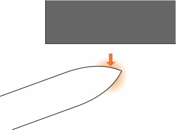
Influence of surroundings
When a ship moves close to a harbour wall, the forward pressure point behaves like a cushion [8] that pushes the bow away (figure 18). At the same time, the aft pressure point draws the stern closer as if magnetically attracted to the wall. The same will happen when the ship passes close to a gently shelving river bank on one side; the bow is repelled and the stern sucked in.
Figure 18
Now picture the scene where the vessel has untied from a wharf ready to depart. As soon as the propeller starts to turn, it sucks water from the narrow gap between the side of the hull and the wall. Fluid drawn through the gap acts as a stream tube with a venturi-like constriction, and here, Bernoulli’s principle comes into play. To keep things simple, we’ll assume that the depth of the tube below the water surface is constant throughout, and that seawater is an ideal, incompressible fluid. At any particular point along the stream tube, the pressure within the fluid has two components: the static pressure \(p\) and the dynamic pressure \(\frac{1}{2} \rho V^2\), where \(\rho\) is the density of seawater and \(V\) the velocity of the fluid at that point. It is the static pressure \(p\) acting perpendicular to stream tube that registers on the hull surface. From Bernoulli’s Law we know that the sum of the two pressures \(p + \frac{1}{2} \rho V^2\) is constant everywhere along the tube, and since the tube narrows within the gap, the velocity must rise and the static pressure must fall – hence the side of the hull is drawn in towards the harbour wall [1].
A related effect happens in shallow water. As recounted in Section M1920, owing to the narrow gap between the underside of the hull and the seabed, fluid speeds up as it passes underneath the vessel; the pressure falls and the hull ‘squats’ deeper in the water. And as we saw earlier in this Section, the ship loses manoeuvrability because the narrow gap also impedes the cross-flow of fluid underneath the hull when the vessel swings round or changes course.
Interference between ships
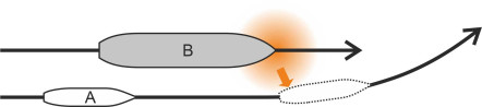
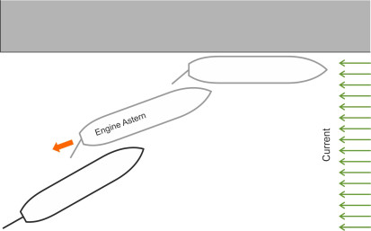
Two ships are said to meet ‘head on’ if they approach one another from opposite directions. In order for them to pass safely, the respective masters will take account of the pressure fields around the bow and stern of each vessel. If they get too close, the bows will repel and the two vessels will swing momentarily off-course, away from each other (figure 19). And after they have passed alongside, the sterns will attract so there is a risk of contact [1] [10]. The outcome is different if the ships are travelling in the same direction. We’ll label the ships A and B and assume that ship A is travelling faster than B and intends to overtake as shown in figure 20. The overtaking manoeuvre is potentially risky for vessel A, especially if it is smaller than vessel B. When alongside, the two hulls attract one another, but as it draws ahead, the stern of ship A is repelled so its bow swings into the path of the larger vessel. The aerodynamic pressure between two lorries travelling in adjacent lanes along a motorway produces a similar effect.
Figure 19
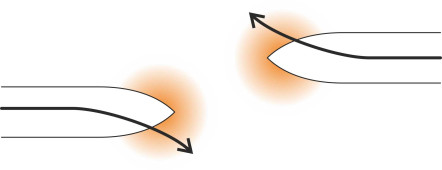
Figure 20
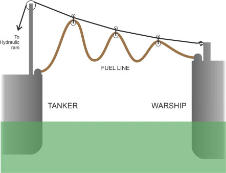
Occasionally, it is necessary to transfer personnel or equipment between two ships. For example, diesel-powered warships typically must refuel in mid-ocean from a supporting tanker every two days during an exercise [15]. In order to maintain control, both must keep moving, so the warship draws alongside while the tanker crew pass the fuel line between them suspended from a ‘spanwire’ rig as shown in figure 21. It is a hazardous procedure because the hulls attract each other, and close cooperation is needed between the crews to keep the vessels moving in parallel at the same speed.
Figure 21
Another challenge arises when a ship gets into difficulties at sea, as might happen if the engine fails during a storm. Other vessels will come to the rescue and eventually the ship will be taken in tow. The problem is that both the towing vessel and the towed vessel tend to speed up and down slightly with each passing wave, and because the motions are not synchronised, the line undergoes widely varying levels of tension. If the line falls slack, the leading vessel will jump forward, and shortly after, the line will draw tight again and may break under the shock as the leading vessel tries to accelerate the trailing vessel to the same speed. In rough conditions, it may be impossible to recover the broken line or get another one on board. One way to reduce the risk is to choose a line made of flexible material so it doesn’t draw tight abruptly, but rather, it stretches and contracts as the tension rises and falls. Old-fashioned rope does this to some degree. When the ships move apart, the towing force builds up over a longer period, and the peak tension is reduced. In theory you can achieve the same result by hanging a weight roughly half way along the line [6].
Tying up
At the end of a voyage, a ship needs protection from the wind and waves so it can unload, refuel, and undergo maintenance. There are three alternatives: it can berth at a quayside, moor at a buoy, or anchor in sheltered water. In each case, there are standard procedures for approaching the site and securing the vessel. Rather than trying to cover them all, we’ll focus on the berthing operation and then briefly consider how lines are used to tie up a ship or attach it to another vessel.
It’s not like parking a lorry. A ship is at the mercy of several influences including the fluctuating pressure of water on the hull and wind pressure on the superstructure. The water pressure arises from wave action, current, and hydrodynamic forces, and it acts in different directions on different parts of the the hull plating, rudder, and propeller blades. The ship’s inertia makes it difficult to control in a confined space, and while a small vessel will manage under its own power, a large vessel will usually need tugs to push or pull it into place.
Most vessels can dock with the wharf on either side, port or starboard. Figure 22 shows a vessel docking on its port side. The easiest method is to approach the wharf (a) travelling forward, and (b) moving against the current or tide. The opposing current can be used as a brake, and it ensures a consistent flow of water past the rudder throughout, which in turn gives the helmsman better steering control. The vessel steers ‘nose-in’ at an angle of around \(25^{\circ}\) to overcome the bow cushion, and when it is within a ship’s length of its berth, the master will put the engines astern and the rudder to starboard; assisted by the ‘paddlewheel effect’, this will draw the stern towards the wharf [9]. The master then orders mooring lines to be thrown onto the quayside, where handlers will loop each line over a bollard built into the structure. Finally, the lines are drawn tight by electric winches aboard the ship. A large vessel may need more than 12 lines to hold it in place, each of which can accumulate a significant amount of stored energy. If the line breaks, the snapback can be harmful.
Figure 22
Conclusion
When handling a cargo ship or a passenger liner, a ship’s master is dealing with forces and motions on a large physical scale. It is common practice to train on a simulator, complete with visual displays and mock-ups of the controls, all operating on the same timescale as they do in real life [16]. As far as I’m aware, the world’s most advanced ship handling simulator is based in the Marine Training Centre in Hamburg-Stellingen [20]. Opened in 2009, it generates a 360-degree field of view, and simulates movement of the bridge in rough weather.
Some of the most demanding manoeuvres take place in shallow water close to shore. On the final approach to an international sea port such as New York or Hong Kong, where the vessels range in size from a few metres to over 500 m long, the master will hand over control to a pilot who knows the area and is trained to handle large vessels in confined spaces. It is the pilot who decides whether tugs are needed, and gives instructions directly to the crew while the ship’s master looks on. Each command is logged so that if anything goes wrong, there is an ‘audit trail’ from which the authorities can establish what happened and why. It’s just one aspect among many others involved in handling a ship. They include navigation, and how to survive rough conditions at sea, two of the topics that we’ll be covering in the next (and last) Section in this series.
A loose end
In an emergency, it is not unusual for the officer of the watch to order the ship’s engines ‘hard astern’. However, it has been suggested [1] that the propeller doesn’t grip the water immediately: one might just as well go slow astern and increase the rpm once the ship has begun to lose way. But is this true, and if so, why?
Acknowledgement
Figure 3: TSS Meridian gyrocompass by Teledyne Marine, http://www.teledynemarine.com/meridian-gyrocompasses?ProductLineID=45 (accessed May 2021).