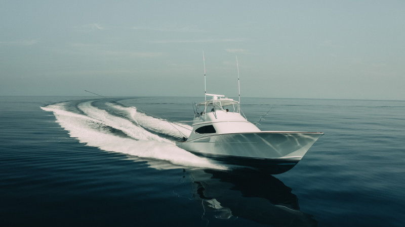
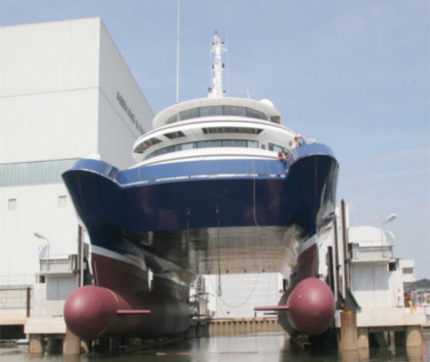
© Donald L Blount Associates
M.1506
Fast ships
A century ago, passenger liners competed for trade by racing each other across the Atlantic Ocean. The last to hold the Blue Riband for the quickest crossing (at over 35 knots) was the United States, reputed to be the fastest liner ever built. Vessels of this size could outrun warships, and during the Second World War, her British equivalent, the Queen Mary, carried in total over a million fighting personnel in a series of dashes across the Atlantic without coming under attack. After 1950, everything changed. Jet airliners captured the passenger market and made the ocean liners obsolete, forcing the shipping companies to switch their attention elsewhere. So they began to build cruise ships for holidaymakers, and fast ferries to handle the growing demand for travel between ports in coastal areas around the world. Cruise ships don’t need to go particularly fast, but ferries do, and new types of the hull were developed to make it possible. Instead of floating in the water, they skated across the surface. In recent decades, the speed target has risen to 50 knots or more, and more radical alternatives have appeared with two or even three hulls.
The planing hull
To move fast, one must lift the vessel at least partially out of the water – i.e., make it plane. When stationary it floats in the same way as a displacement vessel, but it’s designed to rise with increasing speed. The rise begins at the bow when the vessel’s Froude number Fr reaches a value of 1.0 or thereabouts, and the vessel is fully planing when Fr = 3.0. The planing action is described in detail in section M1718; most of the lift comes from the deflection of particles near the water surface, whose downward acceleration generates a reaction in the opposite direction.
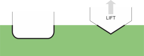
Unlike a conventional passenger liner, a planing vessel is designed to minimise the area of hull in contact with the water. This requires a short hull built from lightweight materials, with a ‘V’-shaped rather than ‘U’-shaped cross-section (figure 1). The bow doesn’t provide much support, and in fact most of the boat’s weight is carried by the aft section, which is almost flat, and relatively wide in the beam near the stern [10]. The next requirement is lots of power. Planing hulls are more efficient when travelling fast, and they need a great deal of energy to do it because the friction rises as the square of speed.
Figure 1
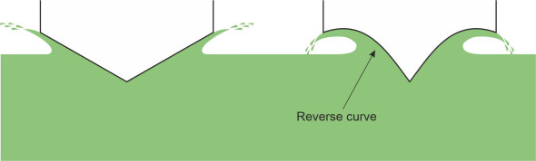
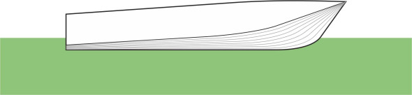
So let’s look at the hull profile in more detail, starting with the cross-section. As shown in figure 2, the sharpness of the vee is measured by the deadrise angle between the sloping hull surface and the horizontal. There may even be a reverse curve to force the parted water downwards as well as outwards, which adds to the lift (figure 3). Either way, the deadrise angle is not uniform along the length of the hull, which is more sharply chined at the bow so that instead of slamming into the oncoming waves it tends to slice through them. This reduces the impact loads, softens the ride, and gives the boat directional stability. A planing hull is more sensitive to wave action than a displacement hull, and in fact the designer will vary the shape to suit the conditions under which it will operate. Offshore craft need a steeper vee because they are exposed to heavier seas, with a deadrise angle amidships of say \(20 - 25^\circ\), while inshore craft need only a shallow vee at an angle of \(10 - 12^\circ\) [5].
Figure 2
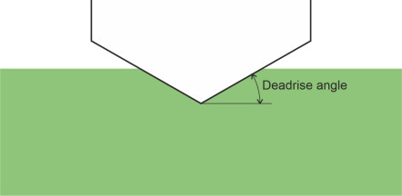
Figure 3
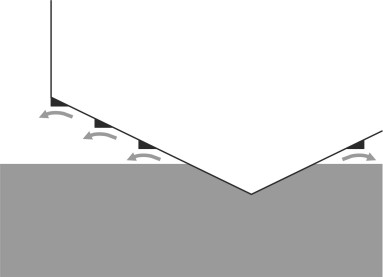
Now let’s look at the hull from the side. One can see from the buttock lines in figure 4 that the longitudinal cross-section changes from a curve at the bow to a straight line that terminates at the transom [5]. This straightens the path followed by the water particles as they slide under the hull. As previously explained in Section M1718, the aim is to prevent the particles from curving upwards and applying suction to the stern, but instead to make them break away from the hull altogether to leave a ‘dry transom’. To reduce the wetted area further, the manufacturer can install trim tabs or an ‘interceptor’ under the stern that the helmsman can use to control the angle of trim (see Figures 27 and 28 in Section M1718).
Figure 4
Stepped hulls
A planing hull will go even faster if its underside is ‘stepped’ as shown in figure 5. The technique is commonly employed on seaplanes. A step breaks the wetted area into shorter sections while leaving the width unchanged (figure 6). The reduced area of hull in contact with the water means less friction so that in general a stepped hull runs faster than a non-stepped hull of the same length and width. But as a designer will tell you, the geometry is critical. In order to separate the wetted area into distinct sections, the step must draw air through the opening on either side to ventilate the flow. If a wave momentarily blocks the opening, the air cannot get in, water is sucked in behind the step, and the resistance increases. If the blockage occurs on one side only, the boat may turn sharply and even capsize. Hence the openings should be well above the waterline [6]. More on this topic can be found in [3].
Figure 5
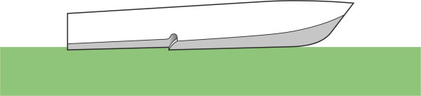
Figure 6
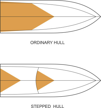
The stepped hull has another characteristic that may confer an advantage or a disadvantage depending on the wave conditions. Since there are two centres of lift, one forward and one aft, the boat will maintain a more consistent angle of trim, for example.
Semi-displacement vessels
A conventional displacement vessel moves quite slowly, at a Froude number less than 0.4. In contrast, a planing vessel must achieve a Froude number of 3.0 or more to minimise resistance. But these two types – the displacement hull and the planing hull - are not the only options. In recent decades, designers have worked out a compromise in the form of the semi-displacement hull that operates at speeds in between.
Figure 7
The semi-displacement hull doesn’t actually plane, but it produces a modest amount of dynamic lift to supplement its buoyancy. At first sight, it looks like a conventional displacement hull, but it differs at the stern. The stern is designed to reduce suction, which would otherwise make it ‘squat’ low in the water at the rear, with the bow elevated at a high angle of trim. As with a planing hull, the buttock lines are straightened aft, terminating at a flat transom. The sharp upturn of the transom causes water passing under the vessel to separate from the hull surface, which prevents suction and allows the stern to rise [9] (figure 7). However the semi-displacement hull has more-or-less conventional rounded bilges at the front, so the vessel can roll more smoothly in a rough sea than is possible with hard chines. You may recall that earlier in Section M1619, we described how the bow wave clings to the curved profile and dissipates energy as it shoots up vertically in spectacular fashion on either side. Designers try to minimise the energy loss by adding rails that deflect the water outward and downward as shown in figure 8, which reduces the wetted area [2].
Figure 8
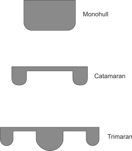
Multi-hulls
One of the drawbacks of a conventional hull is that it rolls from side to side in waves that arrive on the beam, and in extreme conditions may be overwhelmed and capsize. For small craft, it makes sense to link two hulls together in parallel to create a vessel that is more stable than a single hull on its own – a catamaran. The hulls can be conventional displacement hulls or planing hulls.
The rationale for two or more hulls
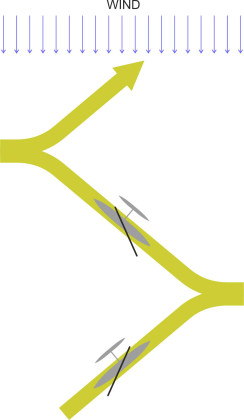
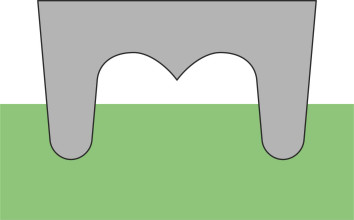
The word ‘catamaran’ comes from the Tamil kattumaram, which means ‘trees tied together’ [4]. The first ocean-going catamarans were built by Polynesians over 1000 years ago and they are still being made in places scattered across south-east Asia and the islands of the southern Pacific. An example from the island of Fiji is shown in figure 9. The basic form is known to the Western world as the proa. It’s really a sailing boat with an outrigger. The main hull carries crew and cargo, while the outrigger - the ama - is weighted to counteract the overturning effect of the wind. Unlike the modern catamaran, the proa doesn’t have a ‘bow’ or ‘stern’. It can move equally well in either direction, and when tacking, it reverses on each leg so the ama always remains on the windward side with the main hull to leeward as shown in figure 10. In the 18th century, the proa was capable of crossing the Pacific [11]), and it could outrun the European sailing ships in James Cook’s expeditionary fleet.
Figure 9
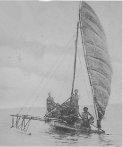
Figure 10
A multi-hull layout has several advantages over a single hull. They are:
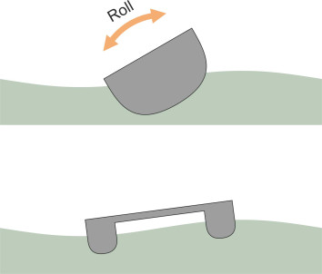
- Sea-keeping: by comparison with a single hull, a catamaran is less likely to overturn. In fact the twin hulls don’t eliminate roll entirely – although the vessel stays parallel to the water surface, each hull traces out the variations in wave height so it rocks from side to side as shown in figure 11. But with its relatively slender proportions each side hull can slice through waves rather than slamming into them, which means the catamaran can maintain speed more easily under rough conditions, and if it’s a sailing boat it can make use of strong winds.
- Deck space: during the 1870s, a few shipping companies carried out experiments with twin-hull paddle steamers in the hope of producing a more comfortable ride for cross-channel passengers [1]. They weren’t successful, but they demonstrated another advantage of the catamaran layout: if the hulls are spaced a little way apart the bridge between them forms a conveniently large area of deck to accommodate passengers and cargo. However, the bridging structure is subject to high ‘racking’ forces that can lead to fatigue cracks [13]. Strong trusses are needed which add considerable weight, so that today, catamarans are usually built from lightweight but expensive materials such as aluminium. This limits their size: in the year 2010, the displacement ceiling was reckoned at around 3000 t [18].
- Wave-making resistance: in certain cases, the catamaran has less wave-making resistance than a monohull having the same total dispacement. For the catamaran to have the same hull speed, its side hulls must have at least the same hull length as the mono-hull. Each will have only half the displacement, so it will be relatively slender and generate correspondingly less wave-making resistance. But the advantage may be offset by increased frictional resistance, because in total, the side hulls have a greater wetted surface area.
Figure 11
How a twin-hull behaves
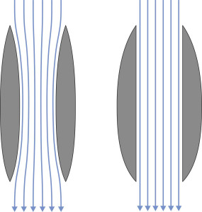
The hydrodynamic behaviour of a catamaran is intrinsically more complex than that of a mono-hull, for two reasons. First, the hulls generate two wave systems that interact with one another, and second, the deck that joins the two hulls together has a significant impact on the vessel’s behaviour in rough water. Let’s deal with the interaction first. Suppose the two hulls are positioned close together. If we look in plan view at the gap between them, we see an appreciable narrowing midway between stem and stern (figure 12). As it flows through the gap, the water speeds up, and according to Bernoulli’s principle, the pressure falls and so does the level of the water surface. In effect, the water ‘sees’ the gap between the two hulls as part of a larger obstruction, and the resistance rises. If you are trying to build a compact vessel, one way to avoid the extra resistance is to widen the bottleneck, which implies making each hull asymmetrical in plan. In one frequently-used arrangement, the inner sides are straight and flat, with the outer sides curved.
Figure 12
Now for the deck. The underside is called the wet deck, and the space below, the tunnel. The wet deck can trap waves: if the vessel pitches in a heavy sea, the underside slams into the water with destructive force. On the other hand, if the tunnel converges towards the stern and the vessel is moving fast enough, the air pressure between the hulls rises sufficiently to form a protective cushion above the water surface, a feature widely used on racing craft. For larger vessels, the underside may be profiled with a sharp, central ‘vee’ to minimise the impact (figure 13) [13]: when the craft meets a wave, the vee bites into the water to generate buoyancy and lift. Because of its sharp profile, the lift is small at first, but it increases progressively with the height of the wave so the impact is gradual rather than sudden. A vessel with this configuration once broke the world offshore water speed record at over 300 km/h [12].
Figure 13
Compared with an equivalent mono-hull, we can summarise briefly the operating characteristics of the modern catamaran as follows. When travelling at low speeds, its resistance is high because the twin hulls have a relatively large wetted area, but at higher speeds the catamaran has lower wave-making resistance. Tunnel planing catamarans appear to be among the fastest offshore powerboats, cruising typically at speeds of 50 knots or more. Details for selected craft appear in [14].
The wave-piercing catamaran
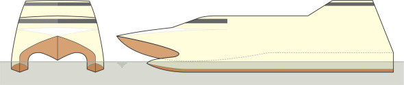
A catamaran can be made to interact with the water surface in ways that are not possible with a conventional vessel. So far we have only mentioned catamarans with conventional displacement hulls, and those with hard chines that rise and plane on the water surface. But with a twin-hull layout, it’s possible to go in the opposite direction and submerge the hull deeper in the water to remarkable effect. In 1971, the Norwegian shipbuilder Westamarin launched what has since become known as the wave-piercing catamaran or WPC for short. Each hull is long and slender, with a ratio of length to beam in the range 10 to 20, twice as large as a conventional ship [13]. Figure 14 shows the twin hulls and wet deck of a hypothetical craft from below. Let’s call it Emma. As with a fast planing catamaran, the wet deck is formed into a vee that lifts the craft smoothly over larger waves [13]. But what distinguishes the WPC is the bow of each hull, which as shown in figure 15 is submerged below the waterline: the vessel generates only modest surface waves with less wave-making resistance than an equivalent mono-hull. Why? Because it produces less disturbance at the water surface. Equally important, it doesn’t have to slow down in rough weather to the same degree as would a conventional ship, which pitches upwards when the hull ‘slams’ into each oncoming wave.
Figure 14
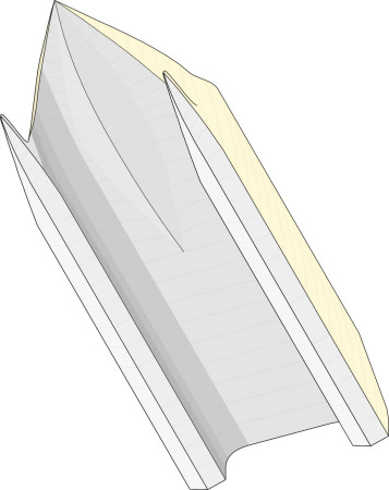
Figure 15
With a cruising speed typically of 35 knots, the WPC gives a smoother ride and is less liable to lose speed in a rough sea [13]. Because it will continue to run in most weather conditions, the WPC has taken over from the hovercraft and other high-speed vessels for coastal ferries. In 1990 the Hoverspeed Great Britain won the Blue Riband for the fastest Atlantic crossing at an average speed of 36.6 knots, breaking the record originally set by the United States on her maiden voyage in July 1952. The boat was built by International Catamarans in Hobart, Tasmania. Details of other notable WPCs are listed in [14].
The SWATH
The distinguishing feature of the WPC is the way the hull volume is distributed at a greater depth below the waterline than is possible for other hull forms. One can carry this idea further. The Small Waterplane Area Twin Hull vessel (SWATH for short) features two buoyancy tanks well below the water surface that support the vessel on stilts [8]: the general cross-section is shown in figure 16. According to one source the concept can be traced back to the submarine [16]. The aim is to make a vessel that is extremely seaworthy, with the buoyant part of the hull relatively unaffected by waves, and with a wave-piercing upper hull that minimises pitch [8]. With greatly increased surface area, the SWATH configuration generates a high frictional resistance and is limited to a maximum speed of about 25 knots [16]. It is also very sensitive to changes in payload because the buoyancy doesn’t change much with draft. Designed as a service vehicle for undersea operations, the first practical SWATH was built in the Netherlands in 1968. It has since been adapted to other purposes, for example, as a coastal fishing vessel.
Figure 16
The trimaran and other multi-hulls
Less common than catamarans are boats with three hulls, the central hull usually larger than the others as shown in figure 17. A three-hulled vessel is called a trimaran. It can be viewed as a single hull with outriggers to provide stability, and some experimental warships have been built in this form, in particular the British RV Triton, which was launched in the year 2000 [8]. The boat manufacturer Austal has since developed this layout for commercial vessels [15].
Figure 17
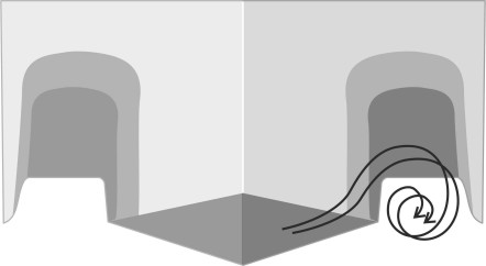
There is also a clever invention known as the M-craft which resembles a trimaran with the three hulls arranged close together in parallel. The central hull provides most of the support, while the outer hulls modify the wave pattern. A better description might be a mono-hull equipped with a longitudinal ‘fence’ on each side, that ‘captures’ the bow wave together with any spray emerging from that side of the vessel and diverts it into a spiral path in the cavity between the hull and the fence as shown diagrammatically in figure 18. Hence there is less wash and less wave-making resistance [17]. The concept has been extended in the form of a five-hulled vessel for service in the US Navy – effectively a catamaran with two outer fences to contain the outer wake and an inner V-section presumably to induce spiral flow between the two main hulls.
Figure 18
Conclusion
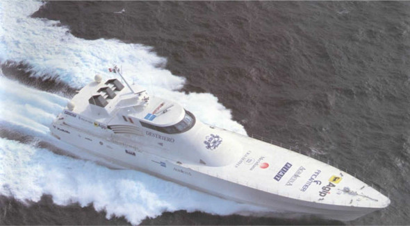
How fast can a ‘fast ship’ go? A lot depends on the conditions, so let’s assume an open sea such as the north Atlantic. A hundred years ago, the standard for the crossing between Europe and the USA – the Blue Riband - was set by passenger liners such as the United States. Although passenger liners no longer compete on this route, a few private owners have since taken up the challenge with smaller craft designed solely to break the record: long-distance speedboats in fact. Some have reached much higher speeds than the 35 knots achieved by the United States. At the time of writing, the record is held by the Italian planing vessel Destriero (figure 19). Only 67 m long and powered by gas turbines, in 1992 it averaged 53.1 knots non-stop [3], equivalent to just under 100 km/h. Over short distances in coastal waters, much higher speeds are possible [12], and some experts consider 100 km/h as a feasible target. Technologically, it could be attained during the next decade or so, but whether craft can operate safely at this speed in crowded coastal waters has yet to be determined.
Figure 19
Acknowledgements
Photo on opening page: Recreational planing craft, by kind permission of Donald L Blount Associates.
Figure 16: The SWATH vessel Silver Cloud built by Abeking & Rasmussen, by kind permission of the owner Alex Dreyfoos.
Figure 19: The Destriero designed by CMN Yacht Design and Donald L Blount Associates, built by the Fincantieri Cantieri Navali Italiani, and launched in 1991. Photo kindly provided by Denaro Francesco and Mauro Parodi of Fincantieri.