© Susanna Rosti Rossini
M.1920
Afloat
The next time you go for a swim, you might turn on your back and float for a while: you won’t feel heavy because the water holds you up, and the supporting forces are not concentrated in one place (your feet) but shared out across your whole body. In the same way, the forces that keep a ship afloat are spread over the submerged area of the hull, so it can carry a heavy load inside a relatively thin shell. In this sense, it’s the most efficient load-bearing structure that an engineer can devise. In this Section, we’ll begin our investigation of waterborne vehicles at a simple level, by asking what makes a ship float. In later Sections, we’ll ask whether it will float the right way up, and how it might handle in rough water.
Buoyancy
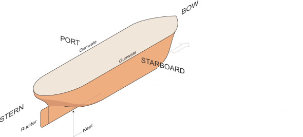
There are many technical terms used in shipbuilding, and we’ll need to be familiar with them, so let’s start by looking at the different parts of a hull.
Figure 1
Hull shape
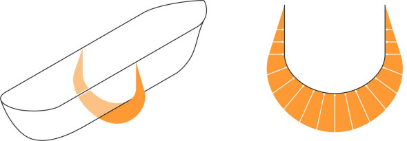
A ship’s hull has four ‘quarters’ as shown in figure 1. They are called port (left side), starboard (right side), bow (front) and stern (rear). The gunwale is the top edge of the hull plating on either side. A critical factor is the level of the water surface: how far up the side will it reach, and will it come close to the gunwale? It depends on the load that the ship is carrying, and varies from moment to moment with the wave conditions that the vessel meets on each voyage, so for design purposes a marine architect will refer to an imaginary surface called the design waterplane. This is the horizontal plane passing through the hull at the level of the water surface when the ship is carrying its design load in perfectly calm condition at summer temperatures (figure 2), and it acts as a reference plane against which other quantities can be measured. The outline of the hull surface where it intersects this plane is called the load waterline or just the waterline, and the area enclosed within the waterline is the waterline section.
Figure 2
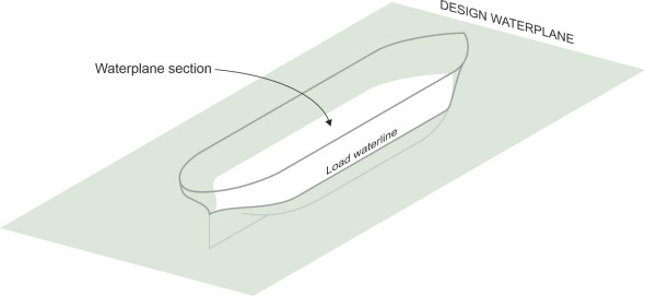
Figure 3
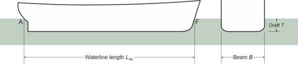
If you are buying a car, you’ll want to know how large it is, and whether it will fit into your driveway or garage. The same applies if you are buying a ship: key dimensions such as the length, width and height tell you where it can moor, where it can put into port, and where it can safely navigate. But to determine its behaviour at sea, the designer has to think not so much about the overall size, but the size of the submerged part of the hull, and particularly its dimensions as measured at the design waterplane. As shown in figure 3, they are
- the waterline length \(L_{WL}\), measured between the foremost and aftmost extremities F and A of the load waterline,
- the beam \(B\), the maximum width of the hull, and
- the draft \(T\), the depth of the hull below the still water surface.
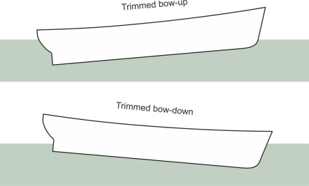
There is another way of defining a ship’s length: denoted by \(L_{pp}\), it is the distance between the bow and stern ‘perpendiculars’. The bow perpendicular is the forward extremity F of the load waterline as before, but the aft perpendicular is usually taken as the hinge on which the rudder is mounted (the rudder post) [6], which may be located some distance forward of A so that \(L_{pp}\) is less than \(L_{WL}\). The draft is usually measured at the keel, which runs along the centre of the hull at its deepest cross-section. Ideally the ship will float with the keel parallel to the water surface. However the bow may be lower than the stern (the ship is ‘trimmed bow-down’ or ‘bow-trimmed’) or conversely the stern may be lower (‘stern trimmed’) in which case the draft depends on where you measure it. All these terms were established several hundred years ago, and are still used today.
Will it float?
At the beginning of the nineteenth century, people doubted whether an iron ship would float. Iron is ‘heavier than water’: if you drop an iron bar into a river it will sink, whereas a wooden plank floats on the surface. True, but a ship is mostly air inside. The water doesn’t know that the shell is made of iron, only that when added together, the iron and the air are not especially heavy, their combined weight per cubic metre being less than that of water, typically around a half. In school physics, we learn that whether a body will float depends on its density \(\rho_b\) compared to the density of the fluid in question. To find \(\rho_b\), we just need to know the body’s weight and volume. In principle, it’s not difficult to measure its weight, and assuming it is completely watertight (no water can get inside), we can also work out its volume, and dividing the one by the other we obtain the density \(\rho_b\). Finally, if \(\rho_{b}\) is less than \(\rho\), the object will float, whereas if it is greater than \(\rho\), it will sink.
However, this doesn’t work for ships, because no ship is completely watertight. It’s a straightforward matter to estimate the weight, but what do we mean by ‘volume’? A large ship has a recognisable interior volume that is sealed off from the outside world by a ‘weather deck’ above the engines and cargo hold. But there are hatches (which are sometimes left open), together with glass windows that can break open in a storm, and ventilation ducts that supply fresh air to the engine room and air-conditioning system. And a smaller vessel such as a sailing dinghy may have no deck at all so the hull is open to the atmosphere. For water-borne vehicles, we have to approach the problem in a different way, and define the ‘volume’ as the volume of the water pushed aside or displaced by the hull.
Figure 4
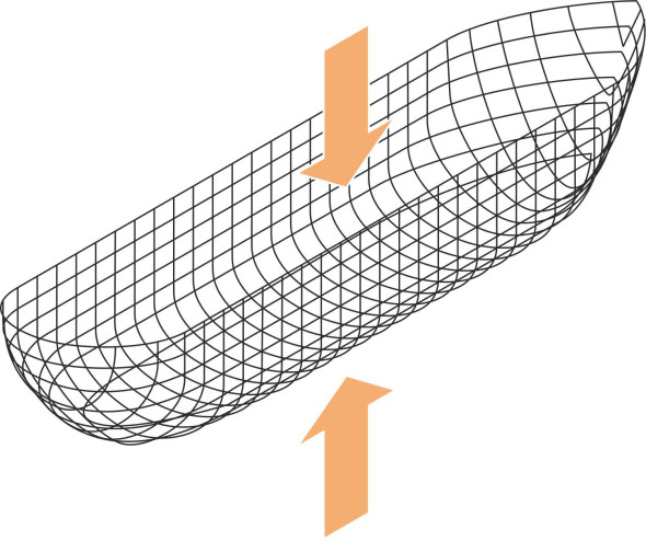
A common-sense way to proceed is to assume that the ship will float, work out the position of the waterplane, and check whether water will pour over the sides. If it does, the gunwales are too low. The hard part is to work out the position of the waterplane. In theory, this is determined by the overall balance of forces: the downward pull of the ship’s weight versus the upthrust of the water, which presses on every square millimetre of the hull. A ship’s hull curves below the waterplane, so that different elements of the hull plating are inclined at different angles to the horizontal. As explained in section F2020, the water pressure acting on each element is proportional to its depth below the water surface, its value being \(\rho g d\) where \(\rho\) is the water density and \(g\) the acceleration due to gravity. The element ‘feels’ a force acting at right angles to its surface (figure 4). This force can be separated into two components: a vertical component and a horizontal component. When the horizontal forces acting on all the elements are added together, they cancel out. Together, the vertical components (treated as positive when acting upwards) represent the buoyancy force that keeps the ship afloat. So if we were to continue with our common-sense approach, the next step would be to try out different positions for the design waterplane and determine the buoyancy force for each one. This would mean re-calculating the pressures and forces acting on the hull each time, and at this point it becomes clear that common sense needs a helping hand.
Displacement
What we need is a method for estimating the buoyancy force without having to take into account the detailed geometry of the hull plating. In ancient times, no-one knew how to do this until the Greek philosopher Archimedes deduced that the buoyancy force or ‘upthrust’ must be equal to the weight of fluid displaced. At the time, it was a significant intellectual leap, but with the benefit of hindsight it’s not difficult to convince oneself that Archimedes’ Principle must be correct. Imagine a replica of the ship’s outer shell made from wire netting immersed in water at the same depth as the original hull (figure 5). Over any small area of netting, the pressure of the water outside must be the same as the pressure acting on the original hull. Hence the total upthrust on the body of water inside the netting is the same as the total upthrust acting on the hull. Conversely, across the area of netting considered, the pressure of the water contained inside must be equal and opposite, otherwise the water would flow from one side of the netting to the other. Hence the weight of water contained within the netting must be equal to the upthrust, and the weight of the ship must be equal to the upthrust too.
Figure 5
It’s an important principle for naval architects because it determines for any given hull shape and size how much weight it can carry. Conversely, if you are designing the vessel to carry a particular load, it enables you to work out the size of the hull. For example, if it must carry 100 000 tonnes including the weight of the vessel itself, you know immediately that below the waterline, the hull must occupy the equivalent of 100 000 tonnes of water, and knowing the density of water you can work out the volume that the hull must enclose and therefore how big the ship must be. A ship is usually described in terms of its displacement, the prime measure of its size and weight. Actually there are several definitions of displacement, for example:
- The volume displacement \(\nabla\) is what it says: the volume of displaced fluid measured for example in cubic metres.
- The force displacement \(\Delta\) is the weight of the displaced fluid in force units, e.g., newtons.
- The mass displacement \(\Sigma\) is the mass of the displaced fluid measured, for example, in tonnes.
Of these, the last is the most widely used in maritime circles. It can range from a hundred kilograms to half a million tonnes for today’s largest supertankers.
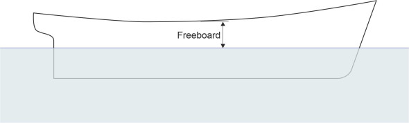
The displacement, of course, refers to the part of the hull that lies under water. But the part that projects above the water is equally important - the sides are built up so the vessel won’t be inundated by waves in a storm. The critical dimension is the height of the gunwales at their lowest point on either side, roughly amidships; measured relative to the design waterplane, it is called the freeboard (figure 6). Not many generations ago, an unscrupulous ship owner might overload a ship so it floated low in the water, insure the cargo for more than it was worth, dispatch the vessel and its crew to a distant port, and claim the insurance money if it didn’t arrive. Growing casualties led to public disquiet that resulted in legislation compelling every ship to carry markings on the hull corresponding to the minimum freeboard. When the ship left port, it was clear for all to see whether or not it was carrying a safe load.
Figure 6
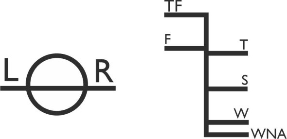
Actually, the markings on a ship’s side – the load line marks – indicate several different water levels each of which apply to a different set of conditions (figure 7). They take account of the difference in density between seawater and freshwater, together with variations in the temperature of seawater between summer and winter. Load line marks are cut to shape from steel plate, welded to the hull amidships, and painted [8]. There are also draft lines at the stem and stern that show the depth of the hull below the waterline that indicate whether the ship can safely manoeuvre in shallow waters, docks and canals.
Figure 7
The water beneath
A displacement vessel is entirely supported by the pressure of the water below. Weighing possibly a quarter of a million tonnes, if it were somehow lifted from the sea and lowered onto dry land it would crush anything beneath, and this leads us to a paradox. Imagine you are a deep-sea diver working on the seabed somewhere in the Atlantic perhaps, when a cargo vessel passes overhead. What would you feel? Nothing. The reason is that a ship’s hull makes a ‘dent’ in sea surface, and since the ship weighs no more than the water that it displaces, it has no effect on the static pressure beneath. The mystery is what happens to the quarter of a million tonnes: it can’t simply vanish into another dimension, because the ship’s weight must eventually be transmitted to the ground along some identifiable ‘load path’. The answer is that when it first takes to the water or is loaded with cargo, it displaces fluid. Momentarily, the fluid piles up around the hull, and launches a wave that spreads outwards across the surrounding body of water, whose average level rises everywhere by a small amount. And with it, the water pressure rises too: the load path diffuses through the ocean to cover every square centimetre of the seabed.
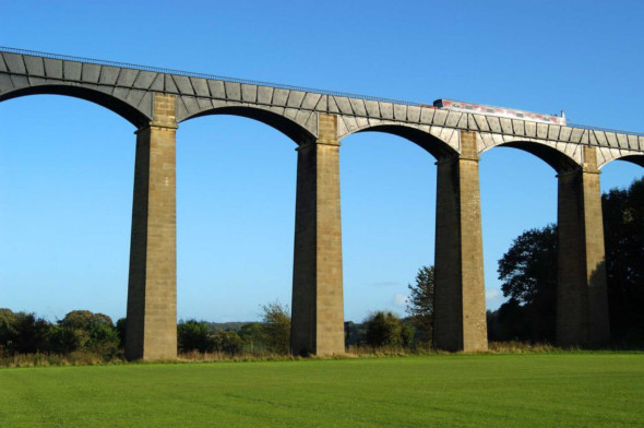
In this way, water spreads the load of a floating body over a large area. We’re not usually aware of it, even when the process takes place in full view above ground. The Pontcysyllte aqueduct was designed by Thomas Telford and completed in 1805. Its cast iron arches carry the Langollen Canal across the River Dee in Wales (figure 8). Picture, if you will, an arch near the centre, and imagine a strain gauge built into the one of the brick piers below the waterway. When a canal boat passes over, the strain gauge will not register any change, because the boat’s weight is spread over roughly 30 kilometres of canal between the nearest lock to the south and the canal terminus to the north. Telford knew this, and it must have simplified the calculations.
Figure 8
Sinkage and trim
As you’ll have gathered, a ship doesn’t always float with the same depth of hull submerged below the waterline. There are many factors that affect a ship’s draft, some of which are ‘dynamic’ effects associated with the ship’s motion, while others are ‘static’ – they arise whether the ship is moving or not. The static effects are easier to explain.
Static effects
The most obvious factor is load. When a cargo ship is heavily loaded, it will settle low in the water because the volume of water displaced must increase to balance the extra weight. On the other hand, when travelling empty, it will ride high in the water, which is not necessarily a good idea, because the rudder and propeller may be partly exposed and lose their ‘grip’ on the surrounding fluid, making the ship difficult to control. So before putting to sea with nothing to weigh it down, a cargo vessel will take on ballast. The ballast is just water, pumped into the cavity between the inner and outer skin of the double bottom, and distributed over the length of the hull to keep it level.
A ship’s draft is also affected by the density of the water itself, which varies from place to place, and from time to time with seasonal variations in temperature. Seawater has a specific gravity of about 1025 kilograms per cubic metre compared with 1000 kg m\(^{-3}\) for fresh water: the difference is largely owing to the salt content. Since seawater is \(2.5 \%\) more dense, the pressure at any given depth is about \(2.5 \%\) higher than is the case in fresh water, and it can support a more heavily loaded vessel. Conversely, when a ship leaves the ocean and heads up-river, it will sink a little.
Dynamic effects
Unlike a speed boat skimming over the surface, a conventional ship settles lower into the water when it starts to move. The phenomenon is known as sinkage. The ship’s master has to be aware of what is going on, because sinkage reduces the freeboard and also reduces the clearance between the keel and the seabed in a shallow channel. The water sucks the ship downwards because the fluid particles follow a curved path under the hull. When they meet the bow, they descend and accelerate under the ship’s bottom. As they approach the stern, they turn upwards again. The effect is analogous to that of the air flowing over an automobile. You’ll see in Section F1816 that almost any land vehicle experiences aerodynamic lift because the pressure acting on the upper bodywork falls as the air accelerates over it. In the case of a ship, the pressure drop occurs underneath and acts downwards rather than upwards. Initially, at low speeds the suction is greater at the front so the bow tends to sink lower than the stern, and the ship is said to ‘trim bow-down’ (figure 9). However, at higher speeds a ship does something else that is unique to floating vessels: it creates a wave system that travels along with the hull, disturbing the water surface so it is no longer flat. Under certain conditions that we’ll explain later in Section M1620, the bow climbs onto the leading wave while the stern settles into a trough – the ship squats. In this way, wave-making influences both sinkage and trim [3] [2].
Figure 9
These effects are compounded in shallow water, because the fluid moves faster as it squeezes into the narrow gap between the hull and the seabed. The higher the speed and the shallower the water the greater the squat [1]. Theoretical analysis with the hull represented as a ‘slender body’ tells us something more specific: that trim and sinkage are both proportional to \(\text{Fr}_{h} / \sqrt{1 - \text{Fr}_{h}^2}\) where \(\text{Fr}_h\) is the depth Froude number given by [4]:
(1)
\[\begin{equation} \text{Fr}_{h} \quad = \quad \frac{V}{\sqrt{gh}} \end{equation}\]where \(V\) is the speed of the vessel and \(h\) is the depth of water. Sinkage becomes important as the depth Froude number approaches unity [7]. For a 100 m long ship, this implies a sinkage of around 1.0 m [5], which is enough to ground the vessel unexpectedly in a shallow channel, for example.
Submarines
When a ship floats on the water surface, it is highly stable in the vertical direction, meaning that if lifted above or pushed below its equilibrium position, it will return to that position of its own accord. The reason is that any downward movement causes the hull to displace more water, so according to Archimedes’ Principle, the upthrust must increase and restore the status quo. Likewise, any upward movement causes the displacement to fall, and with it, the upthrust, so its weight draws it down again. We take this stability for granted, but it doesn’t apply to an object that is fully immersed below the surface, like a fish, a whale, or a submarine.
In fact, a simple model suggests that when totally immersed, any object is intrinsically unstable in the vertical direction, because the static pressure increases with depth. When the object descends, it enters a region of higher pressure, where it will be compressed into a slightly smaller volume so it displaces less water. As a result, the upthrust falls and the object sinks faster. Conversely, any upward movement will carry the object into a region of lower pressure, where it will expand slightly and displace more water. Hence the upthrust increases and it ascends at an increasing rate. According to this model, there are only two possible outcomes: (a) the object rises to the surface, or (b) it sinks to the bottom. Most fish are equipped with apparatus specially evolved to deal with this problem, the swim bladder, which they can inflate or deflate at will to control their vertical position. Sharks don’t have one, and they have to keep swimming so their fins generate the ‘lift’ needed to maintain any given depth. Fortunately, the buoyancy variations are sufficiently small for them to do this without exerting a great deal of effort. So what about submarines?
In principle, a submarine is subject to the same effect. Although it has a cylindrical casing designed to resist ernormous pressures, the structure is slightly elastic. When it dives, the cylinder shrinks by a very small amount and its volume falls. As a result, the buoyancy falls too and the vessel tends to sink further. The process is self-reinforcing so that once the balance is disturbed, a submarine in theory will descend more quickly until it reaches the bottom or the hull collapses. Conversely, if it rises, the pressure falls and the hull becomes more buoyant, leading to an accelerating rate of climb until it arrives at the surface. In reality, this unstable behaviour tends to be masked by variations in the density of water at different depths with salinity and temperature, and like a fish, a submarine is equipped with buoyancy tanks and fins so it can maintain a safe depth. However, if there’s a power failure or the tanks don’t function properly, the crew may lose control.
Where next?
It’s not difficult to establish whether a ship will float in calm water, and how much cargo it can carry without seawater pouring over the gunwales. But other questions remain, for example, whether it will float the right way up. So far, we’ve assumed that when the ship is launched, it will adopt an upright position and stay there. But this depends on the geometry of the hull, particularly its cross-section. In the past, many ships have capsized and sunk in calm water, either because of their shape, or because of the way they were loaded. In the next Section, we’ll find out how a shipwright can predict a vessel’s behaviour before it leaves the drawing board, whether it will be stable, and how large is the margin of safety. The problem is complicated, but it has a surprisingly simple and elegant solution.
Acknowledgements
Photo on title page ‘Gozzo’ by Susanna Rosti Rossini
Figure 8: Photo of Pont Cysyllte Aqueduct, available at: https://www.pontcysyllte-aqueduct.co.uk/attraction/pontcysyllte-aqueduct/ (accessed 13 August 2020), by kind permission of the Canal and River Trust.