M.1715
Floating on air
It seems that a boat will travel faster if it is designed to skate along the water surface, or ride above it on hydrofoils. But it is still vulnerable to impacts that can affect its stability or damage the hull. So why not separate the vessel completely from the water, floating on a cushion of air? Around the middle of the last century, a handful of inventors pursued this idea and made it work. First came the hovercraft, which in calm water could reach speeds approaching 150 km/h. At about the same time, a more radical invention was being developed in the Soviet Union: known as the ekranoplan, it flew faster still at 450 km/h - like an aircraft but only a few metres above the surface. Given such breathtaking performance, for a while it seemed that these two inventions would change the way we travel. Here, we shall try to describe how they work, and ask whether they might have a future role in ocean transport.
The principle of the hovercraft
The hovercraft can more accurately be described as an Air Cushion Vehicle (ACV), or in French, aéroglisseur. It can travel on land or water, riding over obstacles that would bring a conventional vehicle to a halt. In the during the 1950s, the idea was explored for its military potential. By 1959, a research institute in had produced a working prototype [12]. But the focus of commercial development lay in the UK, where the inventor Christopher Cockerell discovered an ingenious way to conserve the pressure within the air cushion so it would support more weight.
Figure 1
Air cushion dynamics
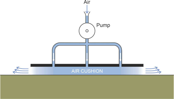
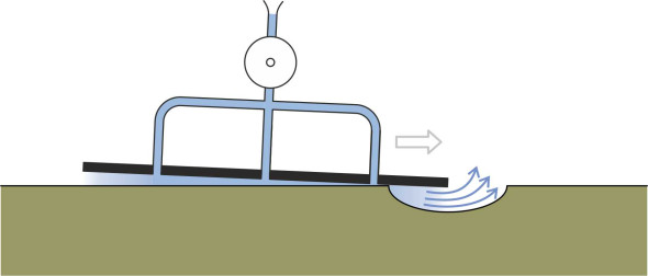
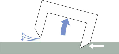
It is not difficult to make a vehicle that will glide over a flat surface on a cushion of air. Start with a rigid sheet, drill some holes in it, and attach a pump on top that forces air into the holes from above, and raises the pressure underneath as shown in figure 1. When the air pressure times the area of the plate matches the weight of the whole assembly, it will rise a few millimetres above the supporting surface. Then a slight push will make it move in any direction with scarcely any friction. This is indeed the principle behind some of the bearings used for high-speed rotating machines. It doesn’t work on rough surfaces because the underside of the plate scrapes over the bumps, and because the air cushion collapses when the vehicle meets a pothole. As the leading edge starts to cross the depression, a gap opens up, the air rushes out, and as shown in figure 2 the vehicle will run aground. Much the same will happen when travelling over rough water. The problem is that the cushion doesn’t contain a sufficiently large volume of air to sustain the pressure.
Figure 2
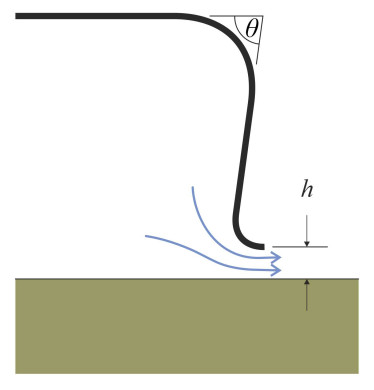
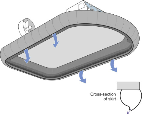
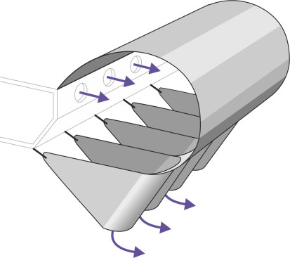
The key is to provide a reservoir, a volume of air sufficiently large to smooth out the fluctuations in pressure that arise when travelling over a rough surface, so a practical hovercraft takes the form of an upturned bowl. The cavity underneath is called a plenum chamber (figure 3). The word plenum historically denotes the opposite of a vacuum, i.e., gas at a pressure higher than atmospheric pressure, hence nowadays, the term ‘plenum chamber’ refers to a reservoir of gas sufficiently large to sustain a more-or-less constant pressure while supplying one or more outlets. Within a hovercraft plenum chamber, the air pressure is typically between 1 and 3 kPa above atmospheric, a modest amount relative to the pressure of the atmosphere itself, which is around 100 kPa. Given a sufficiently powerful engine, pressures of this order can be sustained using a large fan. After entering the chamber, the air makes its way towards the gap underneath the rim, where it exits parallel to the supporting surface (figure 4).
Figure 3
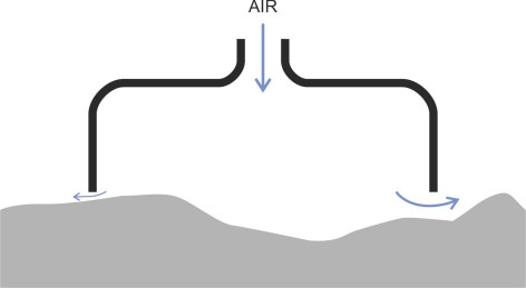
Figure 4
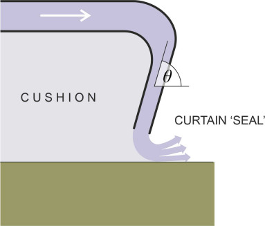
Most hovercraft today are based on the principle of the plenum chamber. But it’s not necessarily the most efficient configuration. For a given level of power, one can increase the lift significantly by creating a peripheral jet round the outside of the chamber, and this was the insight that enabled Cockerell to develop early machines in the UK with engines of relatively modest power output. He began with a model made from a tin can soldered inside another tin can, and pumped air from a vacuum cleaner (with the flow reversed) into the gap between the two. This formed a cylindrical ‘curtain’ around the base, an aerodynamic seal that slowed down the rate of leakage. In the full-sized hovercraft that followed, he angled the curtain inwards so the momentum of the jet opposed the leakage and improved the effectiveness of the ‘seal’ (figure 5).
Figure 5
Plenum chamber
If we assume a simple pattern of air flow under the rim, we can work out a formula for the power needed to sustain the air cushion for either a plenum chamber hovercraft or one with an annular jet. Let’s start with the more straightforward plenum chamber type. The details are given in, for example [9]. We’ll re-work the derivation in a simplified notation. The geometry of the chamber rim is as shown earlier in figure 4. The lift \(F\) provided by the air cushion is equal to the excess pressure \(p\) within the plenum chamber times its plan area \(A\), and at equilibrium exactly counterbalances the weight of the craft \(W\) so that
(1)
\[\begin{equation} W \quad =\quad pA \end{equation}\]Denote the perimeter of the skirt by \(l\). If the hovercraft maintains a constant ground clearance with the gap between the skirt and the ground equal to a fixed distance \(h\) everywhere around the perimeter, then the cross-sectional area through which air leaks under the rim is equal to \(hl\). However, there is some loss owing to the curved path of the streamlines around the lip which we account for by inserting a dimensionless ‘flow coefficient’ \(\phi\) whose numerical value lies between 0 and 1 depending on the angle \(\theta\) of the lip relative to the horizontal. We’ll assume that the velocity of the escaping air is uniform throughout this cross-section, and denote its value by \(v\). Since the pressure difference between the plenum chamber and the atmosphere outside is small, the air can be treated as an incompressible fluid of fixed density \(\rho\). Then we can apply Bernoulli’s equation as if the air were flowing along a stream tube between two locations, and the analysis set out in the Appendix leads to a formula for the power \(P\) needed to sustain the cushion as follows:
(2)
\[\begin{equation} P \quad = \quad \phi hl{p}^{\frac{3}{2}} \sqrt{\frac{2}{\rho }} \end{equation}\]If we substitute for \(p\) via equation 1 this comes to
(3)
\[\begin{equation} P \quad = \quad \phi hl {\left( \frac{W}{A} \right)}^{\frac{3}{2}} \sqrt{\frac{2}{\rho }} \end{equation}\]which shows that other things being equal, the power requirement is proportional to \(h\): in other words, the smaller the ground clearance, the less power needed is to maintain the ride height. In theory, if there is a sufficiently smooth surface for a hovercraft to ride on, P can be whittled down almost to zero.
Another interesting question relates to scale: is a large vessel more efficient than a small one? Here we must make some more assumptions. Let’s imagine a hovercraft as a simple platform that can carry a payload proportional to the area of deck, i.e., proportional to \(A\), and that the dead weight of the vessel is also proportional to \(A\). Hence in equation 3, \(W\) is proportional to \(A\) and we can replace the term \(W/A\) by a constant. The perimeter \(l\) is proportional to the square root of \(A\) and therefore to the square root of \(W\). With \(\phi\), \(h\) and \(\rho\) fixed this leads to the conclusion that
(4)
\[\begin{equation} P \quad \propto \quad \sqrt{W} \end{equation}\]In other words, if you double the weight, you need increase the engine power only by about \(41\%\) . The bigger the machine, the more efficiently it will carry a payload. In reality, our analysis is simplistic and today, engineers use more sophisticated methods to predict the machine’s behaviour. In any case, the deadweight of the structure will increase rather faster than \(A\) in practice, and the engine power needs to increase rather more than equation 4 might suggest [22].
We can extract a little more from equation 3. Suppose we want to build a hovercraft from scratch. What shape should it be? Other things being equal, we want the configuration that minimises the power requirement. Assuming that the ground clearance \(h\), the weight \(W\), and the flow coefficient \(\phi\) are fixed in advance, then the power requirement as determined by equation 3 implies that
(5)
\[\begin{equation} P \quad \propto \quad l \end{equation}\]So let’s explore a few alternative shapes, starting with the circular plan form. Its area \(A\) is equal to \(\pi r^{2}\) and the perimeter \(l\) is \(2 \pi r\), where \(r\) is the radius of the plenum chamber. It is a well known fact that of all the possible shapes, a circle encloses the largest area in relation to its perimeter, so if the sole aim is to minimise the power needed to maintain the air cushion, we would expect a circular plan form to be the optimum shape for a hovercraft, a yardstick against which all other shapes can be assessed. For this optimum case, we have
(6)
\[\begin{equation} \frac{l}{\sqrt{A}} \quad = \quad \frac{2 \pi r}{{\pi }^{\frac{1}{2}}r} \quad = \quad 2 \sqrt{\pi } \quad \approx \quad 3.54 \end{equation}\]By comparison, for a square plan
(7)
\[\begin{equation} \frac{l}{\sqrt{A}} \quad = \quad \frac{4a}{a} \quad = \quad 4.00 \end{equation}\]where \(a\) is the length of each side. It seems that a square hovercraft needs \([(4.00/3.54) - 1] \times 100 = 13 \%\) more power than a circular one. One can repeat the calculation for rectangles of different proportions, and the results are summarised in table 1. It’s noticeable that a long thin rectangle with sides in the ratio 10 to 1 needs about twice as much power as a circular one. Other things being equal, an efficient hovercraft should be not much longer than it is wide, and if possible, circular in plan.
| Shape | Percentage extra power required |
|---|---|
| Circular | \(0.0 \%\) |
| Square | \(12.8 \%\) |
| Rectangular 2x1 | \(19.7 \%\) |
| Rectangular 10x1 | \(96.3\%\) |
Annular jet
Now for the hovercraft with an annular jet. There are several ways to approach the maths but one particular analysis [9] has shown that the power requirement for the optimum configuration is given by
(8)
\[\begin{equation} P_{\text{annular}} \quad = \quad \frac{4hl{p}^{\frac{3}{2}}}{3 \sqrt{3}\left( 1+\cos \theta \right)} \sqrt{\frac{2}{\rho }} \end{equation}\]where \(\theta\) is the angle of the jet relative to the horizontal as shown earlier in figure 5. We can compare this with the power requirement for a plenum chamber configuration as specified in equation 2. Dividing equation 8 into equation 2 we get
(9)
\[\begin{equation} \frac{P_{plenum}}{P_{annular}} \quad = \quad \frac{\phi hl {p}^{\frac{3}{2}} \sqrt{ \frac{2}{\rho }}}{\frac{4hl{p}^{\frac{3}{2}}}{3\sqrt{3}\left( 1+\cos \theta \right)} \sqrt{\frac{2}{\rho }}} \quad = \quad \frac{3\sqrt{3}}{4} \phi \left( 1+\cos \theta \right) \end{equation}\]With \(\theta\) equal to \(60^{\circ}\) and \(\phi\) equal to 0.6 the ratio comes to about 1.17, suggesting that the plenum jet configuration requires around \(17\%\) more power and the annular jet configuration is more economical to run. But in practice, as we’ll see later, the skirt of a hovercraft is made from a flexible material that can easily be damaged. Since an annular jet needs a double skirt that is more expensive to maintain, operators prefer the simpler plenum chamber configuration.
Figure 6
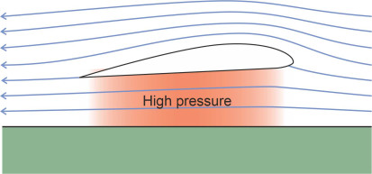
Interaction with the water surface
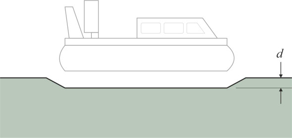
The purpose of an air cushion is to free the craft from the water, and if the cushion does its job properly there will be little or no fluid friction acting on the hull. But in the same way that a conventional ship displaces water, when stationary or moving slowly a hovercraft makes a depression in the water surface. The depression roughly coincides with the plan area of the skirt (figure 6), and one can easily work out the depth \(d\) from first principles. Denote the mass density of water by \(\rho_{w}\). Then the pressure at the surface of the depression must be equal to the depth times density, and this in turn is equal to the air pressure \(p\) within the hovercraft chamber. Hence
(10)
\[\begin{equation} p \quad = \quad d {\rho}_{w} g \end{equation}\]from which we get
(11)
\[\begin{equation} d \quad = \quad \frac{p}{{\rho }_{w}g} \end{equation}\]so the higher the cushion pressure, the deeper the depression. But what happens when the vehicle begins to move? Imagine a fluid particle lying on the water surface in the path of an approaching hovercraft. When the air cushion arrives, it pushes the particle downwards. But water has inertia. It can’t change its position instantly, but instead it will begin to accelerate, moving downwards and forwards ahead of the cushion. This has two consequences. First, water piles up ahead of the bow just as it does with a conventional hull, and second, there is a time lag between the arrival of the cushion and the deformation of the water surface to its full depth. By contrast, a trough forms aft of the stern because the inertia of the water delays its return to the undisturbed surface level. The end result is that the hovercraft moves in a nose-up attitude at a positive angle of trim, and forms a wave system in the same way as a conventional ship.
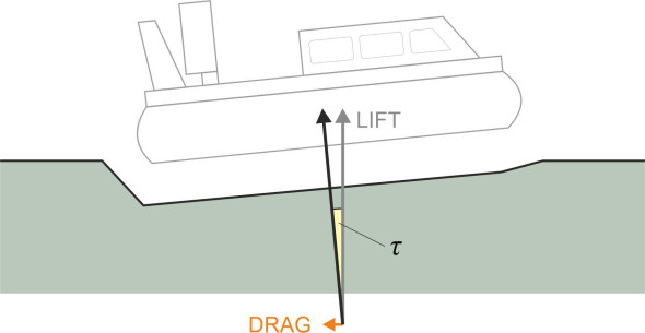
The waves made by the hovercraft absorb energy and add to the overall resistance. The hovercraft can’t ‘feel’ the effects directly because its skin is not in contact with the water, but you can account for the resistance and indeed estimate its value from the attitude of the hull. Because the bow rises and stern falls, the plenum chamber is no longer level, and the cushion pressure has a horizontal component acting in the opposite direction to the direction of motion. Its value is approximately \(W \sin{ \tau }\) where \(\tau\) is the angle of trim (figure 7). The wave-making resistance encountered by a hovercraft seems no different in principle from that incurred by a conventional hull, but unlike the wave resistance for a conventional hull it falls away at higher speeds. This is because the pressure imposed by the air cushion cannot overcome the inertia of the fluid surface during the brief period when it is passing overhead - the water does not have time to get out of the way. Hence as the speed increases, the wave-making resistances rises at first, but then reaches a peak at ‘hump speed’ after which it declines asymptotically to zero. According to one particular analysis the hump speed corresponds to a Froude number of about 0.56 [10].
Figure 7
A hovercraft experiences two other forms of resistance that don’t arise with conventional vessels. The first is momentum resistance [7]. When the craft is moving at speed, the fan sucks in air from the surrounding atmosphere and carries the air with it in the plenum chamber before it leaks away under the skirt. In order to travel with the vehicle, the air must be accelerated to the same velocity, and the vehicle must therefore supply it with kinetic energy. This energy loss is proportional to the square of the forward speed. Usually it is quite small. The second form of resistance arises from the friction of the skirt in contact with wave crests in rough water: in general, the deeper the cushion, the more easily it deforms and the lower the drag. But in calm water the skirt resistance is small and it is the propensity of the air cushion to generate its own waves that dominates. Since the wave-making resistance falls away at high speed, given a smooth water surface a hovercraft can travel very quickly indeed.
Air cushion vehicles
Ideally a hovercraft should meet three requirements. First it should travel fast. Second, it should cope easily with rough surfaces. Third, it should float close to the ground (or water) with the smallest possible gap around the perimeter so the air cushion doesn’t leak away too quickly. The last two requirements conflict, presenting the designer with a conundrum that for a while hampered the development of the hovercraft as a practical means of transport. Hovercraft as we know them today first emerged during the late 1950s. The British effort was led by the Saunders-Roe company based at Cowes in the Isle of Wight. The company specialised in seaplanes, and its first hovercraft, the SR.N1, looked more like a flying saucer than a sea-going vessel. Weighing 3.5 tons, it was built originally in 1959 to the design of Christopher Cockerell. With a jet curtain but no skirt to contain the air cushion, the hull rode at a height of 45 cm above the ground to allow movement over obstacles, and the engine had to work hard to maintain the flow of air that exhausted rapidly from underneath the hull.
Skirts
However in 1961, the Saunders-Roe engineer C. H. Latimer-Needham added a flexible skirt to the SR.N1 that greatly improved its performance. In cross-section, the skirt was shaped like a nozzle so it would create a peripheral jet curtain (figure 8). But it quickly wore out. The fringes of a hovercraft skirt are battered by wave crests, and fluttering in the air stream, the rubberised material tends to de-laminate. Moreover as we’ll see later, when the vessel smashes into a wave the panels at the leading edge can collapse and cause an upset.
Figure 8
Rather like the automobile tyre, the hovercraft skirt needed a great deal of painstaking development into a configuration that could keep its shape, flex easily over wave crests, and resist levels of attrition that would tear ordinary fabric to pieces. During the late 1950s the French designer Jean Bertin patented a system that effectively replaced the peripheral skirt with a set of smaller cells or jupes as shown in figure 9. In Britain, Dennis Bliss of Hovercraft Development Ltd (HDL) persevered with the idea of a peripheral curtain in the form of a convoluted or segmental skirt as shown in figure 10. It deformed more easily and allowed the air gap to be reduced, so the craft could carry a greater payload for a given engine size. It had two distinct structural layers. The upper part was an envelope attached along its upper edge to the frame. It bulged outwards around the periphery and formed a flexible but stable foundation for the lower part, which consisted of an array of segments or ‘fingers’ attached to the underside of the envelope that could deform individually over a rough surface. They were anchored at the bottom to the vehicle frame by cord attachments [9]. There were no nozzles so the air flow acted as it would in a simple plenum chamber. Skirts of this type are still used on smaller machines today.
Figure 9
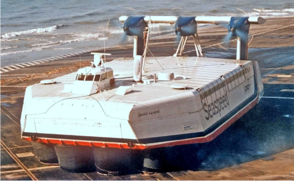
Figure 10
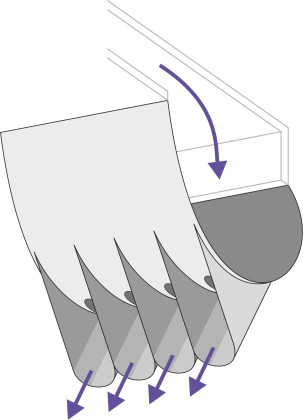
Subsquently, the British Hovercraft Corporation developed a refined version in which the upper panel was attached along both edges to form a closed tube that ran round the circumference like an automobile tyre. Inside there were diaphragms to stiffen the structure as a whole (figure 11). Most commercial hovercraft today have skirts based on this design. The bag is maintained at a pressure slightly higher than the plenum chamber. Holes along the underside act as nozzles, directing air into the ‘fingers’ below, which are shaped to direct the air stream inwards. The fingers take up most of the deformation needed to ride over waves, while the bag provides a stiffening support. In the case of larger machines, the rigid part of the hull floats around 2 metres or more above the supporting surface, so the craft can negotiate 2m waves.
Figure 11
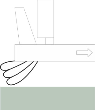
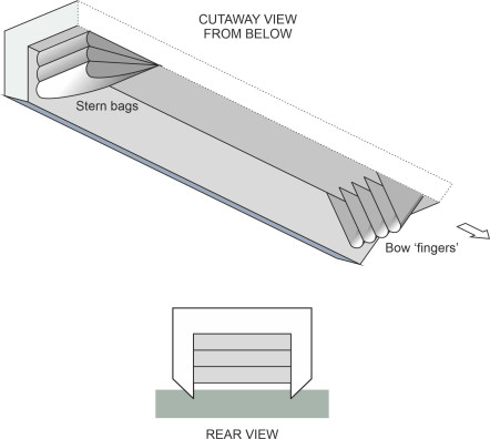
Skirts are usually made from woven nylon impregnated with rubber or neoprene, the bow and stern skirts being reinforced with ‘rip-stop’ to prevent tears. The construction varies in detail around different parts of the hull. At the bow, the bag is deeper and to stabilise its shape, it may be reinforced with a transverse inner panel, and operate at a higher pressure than the rest of the skirt. At the stern, a rather different problem arises. As you might imagine, unless they are modified in some way the fringes of a bag and finger skirt are likely to scoop up water at speed (figure 12) and thereby cause unnecessary drag. One solution is to replace the skirt at the rear with a ‘planing skirt’, which is built up from two or three loops of flexible material (figure 13).
Figure 12
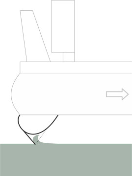
Figure 13
Sidewall air cushion vehicles
Many regard the flexible skirt of the hovercraft as its Achilles heel. One way to reduce the rate of wear and improve reliability is to replace the panels along the sides with rigid hulls or sidewalls. Some refer to a vehicle built this way as a Surface Effect Ship (SES). It is essentially a cross between a conventional boat and a hovercraft: the parallel sidewalls extend below the water surface like the hulls of a catamaran (figure 14), and they provide some lift together with directional stability. This leaves a transverse section of flexible skirt at the bow together with another at the stern, both of which are designed to be robust and easily maintained. Like those of a conventional hovercraft, the bow skirt is constructed using a bag and finger system, while the one across the stern is a planing skirt as shown in figure 13.
Figure 14
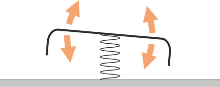
Interestingly, the plenum chamber can resonate like a musical instrument, although the frequency is well below the audible range because a typical chamber is much larger than a kettle drum or an organ pipe. Think of the air inside as a spring that supports the hovercraft at the centre of the hull. Because the air is elastic, the hull can bounce up and down at the resonant frequency of the spring, which for a medium sized vessel might be in the region of 2 Hz [2]. If the hull passes over a series of sea waves at this rate, it can shake sufficiently hard to disturb passengers in the same way as a bus riding over a cobbled road. A similar effect can occur with ordinary hovercraft [21].
Incidentally, a flexible skirt itself has a musical quirk of behaviour. When travelling at low speed or hovering in a stationary position, it is liable to vibrate at a low frequency with the hem alternately rising clear of the water and letting air out, then falling to re-seal the perimeter [19], in much the same way as a musicians lips vibrate when blowing a trumpet.
Although the sidewalls create additional drag that makes it slower than a ‘pure’ hovercraft, the SES configuration has several advantages. First, if the pressure in the plenum chamber fails, the vessel will still operate as a catamaran (although it will float lower in the water than it would when fully inflated). Second, the sidewalls reduce air leakage by comparison with a flexible skirt. Third, the vessel can be driven by conventional propellers or waterjets, which makes it easier to control. Finally, it is possible to scale up the sidewall configuration to ships of considerable size (of the order of 1000 tons) by stretching it lengthways without necessarily increasing the area of flexible skirt.
Power and performance
During the 1960s when air cushion vehicles first came to public attention, people imagined they would replace ordinary ships for passenger transport. Because there was almost zero friction, they didn’t need a great deal of power to push them forward and in fact about two thirds of the total engine output was devoted to maintaining the air cushion. Crudely, the total power requirement for UK hovercraft was about 30 kW per tonne, less than any other type of vessel operating at comparable speed [14]. Like hydrofoils and planing craft, hovercraft were made (and still are made) as light as possible so as not to waste power maintaining the air cushion, and also to avoid making a large dent in the water surface that would sap energy by creating waves. Early machines were conceived and constructed more like aircraft than boats. They used lightweight materials (riveted aluminium) and gas turbine engines. Crucially, the gas turbines provided enormous power within a relatively light package, and the result was a very fast, lightweight machine. After a series of modifications, even the experimental SR.N1 reached 68 knots, equivalent to 126 km/h or 78 mph [8]. The SR.N4 was designed at cruise at 70 knots and was said to have reached 90 knots with a light payload [29]. However these figures don’t tell the whole story. A hovercraft doesn’t have a well-defined ‘maximum speed’ because the speed at which it can travel without risking damage depends on the wave conditions, a point to which we’ll return later.
Over the years, gas turbine engines have lost favour with operators keen to minimise costs in a competitive market. A gas turbine consumes a great deal of fuel, whose weight on a long journey tends to cancel out the benefits of a light engine. Also, a gas turbine tends to corrode in a salty atmosphere and needs frequent overhauls by highly-trained staff in a specialised workshop. The best alternative is the diesel engine. Although heavier than a gas turbine per kW generated, since the 1960s, its power-to-weight ratio has improved, and provided it is air-cooled, operators prefer the diesel because it is robust and relatively cheap to maintain.
Also, early hovercraft were noisy. They were driven by aircraft propellers mounted on top of the hull: those on the SR.N4 were 6.4 m in diameter [14], mounted on pylons that could swivel independently to give the pilot close control during manoeuvres. Propellers of this kind couldn’t easily be enclosed, but on most hovercraft today, the propellers have a fixed axis and are surrounded by ducts that significantly reduce noise emissions.
Hovercraft operations
The hovercraft is almost unique among moving vehicles. Like a spaceship, it has no sense of direction. Since it doesn’t ‘grip’ the surface over which it moves, it can just as well go forwards, backwards or sideways, and when set in motion the hull doesn’t necessarily turn to point in the direction of travel. This makes the control of a hovercraft an interesting challenge. The forces that control its motion - acceleration, braking, and yaw - are created aerodynamically through air jets and control surfaces. It’s all a matter of action and reaction.
Controlling a hovercraft
The air that leaks out of the cushion around the rim can itself be used to control the motion of a hovercraft. This applies particularly to small craft of the kind used by enthusiasts for sport or recreation, craft that usually carry a single person. Imagine yourself as the ‘pilot’. You can make it move in any given direction by shifting your weight. For example, if you lean forwards the stern will rise, opening up the gap between the skirt and the supporting surface and allowing more air to escape at the rear. The reaction will propel the craft forwards. Similarly if you want to move to the right you lean your body to the right. In the case of a larger machine it is less easy to shift the centre of mass in this way, but the designer can still exploit the pressure of the air cushion to provide the motive force by incorporating valves that the pilot can use to increase or decrease the pressure of the air delivered to different sections of the perimeter. Alternatively one can install a system for raising or lowering the skirt at different sections of the perimeter. However, most designers prefer conventional aerodynamic devices such as propellers, air rudders, and puff-ports.
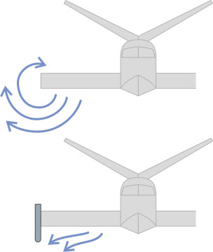
Of these three, it is the propellers, preferably mounted in ducts to reduce tip noise, that provide the thrust for forward motion (figure 15). Since ducted propellers are usually fixed in position they can only propel the craft fore-and-aft. However, two ducts side by side can provide a yawing moment if the speed or pitch of each propeller is varied independently. An alternative used on the Saunders-Roe machines was to mount the propellers on swivelling pylons (figure 16). As well a yaw moment, they can provide a lateral force to counter a beam wind or a lateral current that tends to push the craft sideways. Thrust is varied by varying the pitch of the propeller blades. In principle, a swivelling propeller needs two separate controls: a yoke to vary the pitch and a rudder control to set the angle at which the pylon swivels [17].
Figure 15
Figure 16
Air rudders work like the rudders on conventional aircraft. They are usually mounted in pairs at the stern, each with a moveable control surface that can be swivelled to provide a lateral thrust - provided the air is moving past them quickly enough to generate a significant aerodynamic force. It helps if the rudders are mounted in the slipstream of the propellers. Finally, ‘puff ports’ are openings in the side of the hull through which air can be blown from the plenum chamber: they provide relatively modest control forces but they are simple and cheap to install [17].
So if you were the pilot, how would you make the craft go where you want it to go? Consider , for example, two simple tasks. The first is to travel along a straight course between two fixed points A and B say. Assuming calm conditions with no wind, one way forward is to turn the hovercraft first, so it is pointing in the direction of B. This is easy if the craft is fitted with swivelling pylons or puff ports; the devices are usually arranged so you can apply a lateral force at the bow and an equal and opposite force at the stern, and the resulting torque will spin the vehicle around its vertical axis. Otherwise you’ll need to get moving first and use the air rudders at the stern to make the craft turn; if instead it is fitted with twin ducted propellers that are fixed in position, you can apply unequal power to the propellers to achieve the same effect. But whatever method you use, you must later apply opposite torque to halt the rotation when the craft is pointing towards B. The final step is to power ahead using ducted propellers (or pylon units with the propellers pointing astern) to provide the forward thrust.
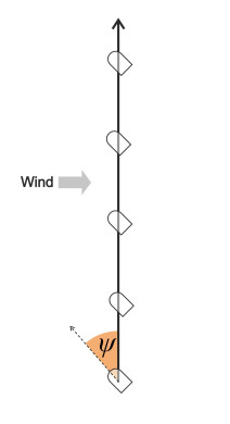
Usually, however, the wind will affect your progress. A wind from the stern will help you to reach B more quickly than would otherwise be the case, a headwind will slow you down, and a wind from the side (a beam wind) can speed you up or slow you down according to the angle it makes with AB. Surprising as it may seem, the range of angles over which the wind slows you down is larger than the range over which it speeds you up, and you’ll find the explanation in Section F0515. At any rate, you will need a degree of sideways thrust to prevent the wind from blowing you off-course. In principle this can be provided either through swivelling propellers or puff ports. Otherwise, you will need to point the vessel upwind of B, with your ‘crab angle’ \(\psi\) fixed according to the strength of the wind (figure 17).
Figure 17
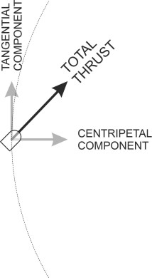
Now let’s look at turns. Like any vehicle, a hovercraft needs centripetal force to make it follow a curved path. As is the case with a crosswind, this requires a lateral thrust, at right-angles to the direction of motion. Again, this thrust can be provided via swivelling pylons or puff ports, possibly augmented by heeling the machine towards the centre of the turn so that more air leaks from the ‘high’ side of the cushion. Otherwise, the pilot must yaw the craft relative to the direction of motion, using some of its forward thrust to provide the centripetal force (figure 18).
Figure 18
Given the different devices that can be used to manoeuvre a large hovercraft you won’t be surprised to find a complicated array of hand and foot controls in the pilot’s cabin, much like the controls in a modern jet aircraft, including a ‘yoke’ or footbar to control yaw. There is no standard layout. Yet manoeuvring at high speed in crowded waters requires skilful navigation, and because some of the control sequences are critical to the safety of the machine and its passengers, pilots need a high standard of training. Surprising as it may seem, the sea-keeping of an air cushion vehicle is relatively poor [7], and it is less comfortable to ride in than a hydrofoil [4]. The hull rises and falls as the skirt impacts the wave crests, and the pilot must slow down in rough weather. Worse, a hovercraft may not be stable even in calm water, as we shall now see.
Sea-keeping and stability
Almost the worst thing a ship can do is to capsize. A conventional ship has a narrow hull that rolls from side to side, and in extreme conditions it can roll beyond the point of no return until it lies upside down in the water. But what about a hovercraft? It’s shape is different, more like a plate lying on a table, and one can’t readily imagine it flipping over. However, the plenum chamber rests on an air cushion as if balanced on a spring, and there’s little to stop it from tilting in any direction over a range of several degrees (figure 19), so when it travels at speed with the water rushing past underneath, the crest of an approaching wave may collide with the skirt and cause a wobble. It’s also worth remembering that a hovercraft is much lighter than other vessel types, and is more sensitive to aerodynamic forces.
Figure 19
In March 1972 an SR.N6 hovercraft overturned on its journey across the Solent between the Isle of Wight and the UK mainland, an accident that cost several lives [13]. Conditions were poor, and seeking calmer water, the pilot was following a course that lay close inshore parallel to the beach. While the hovercraft was moving in the trough between two waves, presumably side-slipping across the water surface, the skirt collapsed along the shoreward side and was dragged underneath the hull. The resulting shift in the centre of pressure within the plenum chamber together with the impact of the wind and waves were sufficient to lift the hull and turn it over completely.
Over the years there have been several instances of skirt collapse leading to structural damage or worse. Most have occurred away from the shoreline, and in relatively calm water. The circumstances vary but the process tends to follow a common pattern. It is triggered by a phenomenon called tuck-under: a deformation of the skirt that usually starts at the bow [16]. The hem of the skirt dips into the water, which drags the skirt inwards towards the centre of the plenum chamber. This reduces the area of the supporting cushion in the critical region under the bow (figure 20) and shifts the centre of pressure rearwards. Hence the bow drops further and the drag on the skirt increases. We now have the elements of what analysts call a divergent instability. Lacking support, the bow drops and the hull itself ‘ploughs’ into the water. The resulting drag force causes violent deceleration that can reduce the speed almost to zero within two or three seconds [15]. If the hull is not aligned precisely in the direction of motion, it can pivot around the point of contact, exposing the port or starboard side to the onrushing water. At this point the vessel can even overturn (figure 21).
Figure 20
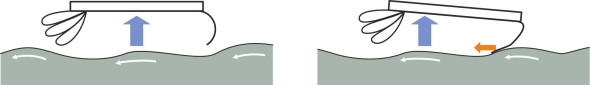
Figure 21
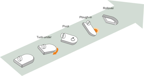
The greatest risk of overturning occurs when the hovercraft is travelling downwind. A sudden gust acting on the propellers high above the waterline tends to push the bow down and force the skirt to tuck under. Such incidents were common with early craft during the 1960s and 70s. Just under one third of all the 155 major accidents that occurred to hovercraft operating from western countries between 1963 and 1978 involved overturning, apparently following a tuck-under, yaw and plough-in [13].
A sidewall craft too can overturn although the mechanism is different. When the SES follows a curved path, the hull on the outside of the curve prevents the vessel from slipping sideways. If you look at the hull in cross-section you can visualise the reaction of the water exerting a heeling moment [3] that can cause the vessel to roll (figure 22). If the inner sidewall rises above the water surface air will leak under the keel, and like an aircraft jet engine will exert a lateral force that increases the degree of sideslip and therefore increases the overturning moment. During trials, there have been at least two cases of vessels overturning in this way, one in the USA and one in China.
Figure 22
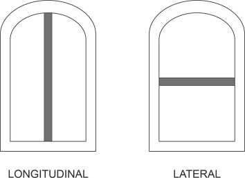
Following these accidents, designers set about improving the stability of hovercraft and SES vessels when travelling at speed. Fortunately, in the case of the hovercraft there are two practical remedies. First, one can divide the plenum chamber into separate compartments with air supplied independently to each section. The dividing walls are made from tubes of inflated skirt material that are nearly as deep as the peripheral skirt [18]. Known as stability trunks, they can be installed in different configurations as shown in figure 23, but the underlying principle is the same in each case. Let’s look at the first example shown in the Figure, which shows the plenum chamber divided longitudinally into a port compartment and a starboard compartment. When the craft heels to port, say, the port compartment is squeezed and as a result the air pressure rises. The resulting torque tends to restore the hull to a horizontal position, so the overall effect is to improve stability in roll. Similarly, a trunk placed laterally across the centre of the plenum chamber as shown in the right-hand part of figure 23 reduces the tendency to pitch nose-down.
Figure 23
Another remedy is to re-configure the section of skirt across the bow. The aim is to prevent it from being dragged underneath the hull by controlling the way it distorts when it hits the water. Designers have tried several variants. They include (a) internal diaphragms, (b) a more bulbous profile as developed by the British Hovercraft Corporation, and (c) a ‘responsive skirt’ that distorts outwards ahead of the hull when impacted by the water, which increases the total area of cushion and draws the centre of lift forwards, resisting any tendency of the hull to pitch nose-down [15].
ACV services
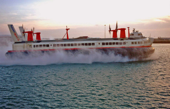
The hovercraft is potentially a very fast machine that can operate in water too shallow for conventional boats. It can also ‘land’ on a sloping apron to load passengers and vehicles more quickly and safely perhaps than at a conventional quayside. The first full-scale experimental hovercraft, the SR.N1, was launched in 1959, and in June that year it crossed the channel between England and France. Regular ferry services started in 1968, taking about half the time required by conventional vessels. A special terminal was built at Ramsgate to service traffic. In its day, the SR.N4 Mk3 was the world’s largest air cushion vehicle. Designed to carry 420 passengers and 55 cars at 70 knots, it operated for nearly 30 years.
But the technology was not well adapted to a rough sea environment. Larger machines were powered by gas turbine engines whose maintenance called for specialised facilities more typical of an aircraft hangar than a boat shed, together with appropriately trained (and expensive) maintenance staff. The hulls were built more like an airliner than a ship, mostly constructed from lightweight aluminium alloys vulnerable to damage and corrosion. The skirts quickly wore out. Crucially, the operating speed fell sharply in rough seas - indeed a hovercraft couldn’t operate at all in waves much greater than the skirt height, and cross-Channel ferry services between France and the UK were often cancelled in bad weather.
So the economic case eventually swung against the hovercraft because of its high operating costs. With competition from hydrofoil services together with the opening of the Channel Tunnel in 1994, it steadily lost ground, and by the year 2000, across the world there were only about 2000 vessels still operating [11]. Eventually, as we’ll see in a later Section, the wave-piercing catamaran came to dominate most of the world’s fast ferry services because it was more reliable, more robust, cheaper to run, and more comfortable to ride in during bad weather. But in the meantime, there was a further twist in the tale of air-cushion craft that opened up the possibility of even greater speeds and another revolution in fast sea transport.
The ekranoplan
Between 1945 and 1991, countries of the Western Allies were engaged in a ‘cold war’ with the Soviet bloc that lasted for over 40 years. Spy planes and satellites on both sides of the political divide kept watch on each other’s activities using high-resolution cameras to photograph movements and installations on the ground. During the 1970s, pictures began to arrive at the Pentagon that showed something unusual. Nicknamed the ‘monster’ (figure 24), it was a vehicle that skimmed across the water at breathtaking speed. What could it be, and how could it move so fast?
Figure 24
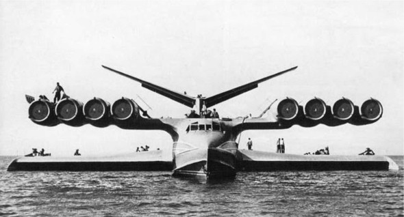
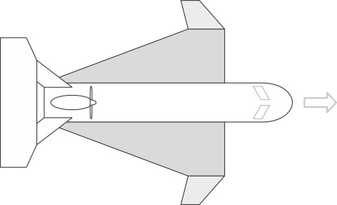
The vessel turned out to be a flying machine that relied on the pressure of the air flowing underneath a stubby wing to support its weight a few metres above the water. The principle was not new. Engineers had known for decades that low-flying aircraft gained extra lift when close to the ground that pilots could use to cushion a landing, an effect called the wing-in-ground effect (WIG) (figure 25). During World War 2, when their fuel ran low air force pilots used the effect to get back to base [1]. In 1935, the Finnish engineer Toivo Kaario built a one-person experimental machine that travelled over ice and snow supported by a ‘captured air bubble’ [23]. What surprised the western allies was the size of the monster together with the speed at which it travelled. At the time it was the largest flying machine ever built. At 544 tonnes it weighed more than a Boeing 747 jumbo jet and cruised at 450 km/h around 4 metres above the water. Data for this and other Soviet and Russian WIGs can be found in [24]. In the USSR they were known as ekranoplans. Most were conceived and developed under the direction of Rostislav Alexeeyev (1916-1980), two of the best known being the Orlyonok and Lun. The Orlyonok or ‘sea eagle’ was designed as a troop carrier. The Lun carried guided missiles. They could both fly under enemy radar and deliver their payload almost before the enemy realised what was happening.
Figure 25
How it works
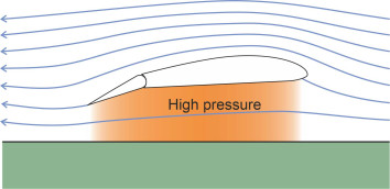
Unlike a hovercraft, a WIG machine doesn’t need a plenum chamber or fans to make an air cushion. Instead it relies on its speed to ram air into the gap between the underside of the wing and the water surface, which acts like a constricted passageway that slows down the air and (in accordance with Bernoulli’s Law) makes the pressure rise [30]. But when the vessel lifts itself clear of the water it doesn’t generate any surface waves so there is no wave drag [23].
The WIG effect works only within a limited regime known as the Surface Effect Zone (SEZ), which extends to a height above the water roughly equal to the wing chord \(c\) (figure 26). Within this zone, the closer the wing is to the water, the greater the pressure increase and the greater the lift. Conversely, for any given weight of machine, the greater the wing chord, the higher it can fly and thereby remain clear of the wave crests in rough water. That’s why the Russian ekranoplans had stubby wings with a deep chord, quite unlike those of a conventional aircraft. And because they were short and stubby, the wingtips didn’t foul the water when the vessel banked during a turn.
Figure 26
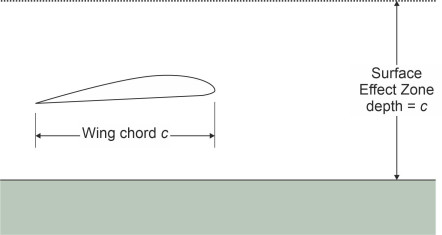
Figure 27
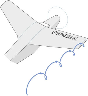
The WIG configuration has a further benefit that’s less easy to explain. As with any aircraft, each wing generates a vortex (figure 27). The vortex comes from the air flowing through the high pressure zone underneath the wing, which spills around the wingtip into the low-pressure zone above. But as figure 28 shows, the presence of the water surface constricts the vortex so there is less downwash and less induced drag than would normally be the case [23]. Moreover, the wingtip plates or ‘fences’ that are installed on many craft help further to suppress the spillage (figure 29). The result is that for a flying height around one tenth of the wing chord, the ratio of lift to drag may be as high as 20 over calm water [26]. This makes the ekranoplan very efficient, needing only half the power of an aircraft of the same weight travelling at the same speed [32].
Figure 28
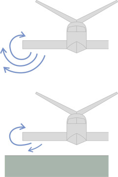
Figure 29
But to achieve all this, the WIG must first climb out of the water. Taking off is hard work, because the vessel must start by planing along the surface like a speedboat, creating enormous drag. It is the energy needed to overcome this hydrodynamic drag that determines the size and configuration of the power plant [39]. For small craft the problem is not too difficult: a powerful turbojet or piston engine with a ducted propeller will get it up to speed. But a large craft needs additional lift to open a sufficient gap between the wings and the water surface for the ram effect to take hold. Many of the early Russian machines were equipped with an array of turbojet engines called boosters mounted at an angle on the nose so the exhaust could blow underneath the wings. This was the function of the eight turbojets that appear prominently in the photo of the Caspian Sea Monster shown earlier in figure 24. Such vessels are known as Power Assisted Ram WIG vessels or PARWIGs for short. Today, lighter machines carry ducted propellers that can swivel downwards (figure 30). The booster lift is further enhanced by wing flaps like those on a conventional aircraft. When lowered, the flaps form a constriction at the rear that slows down the air further (figure 31) and increases the pressure. Overall, for any given wing area, the flaps allow the take-off speed to be reduced. Alternatively, for any given take-off speed, the wing can be made smaller with less drag so the craft operates at a higher cruising speed [24].
Figure 30
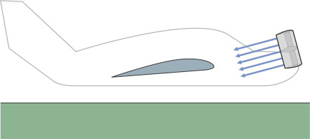
Figure 31
The boosters aren’t needed when the vessel reaches cruising height. The forward thrust is provided by a smaller engine that uses relatively little fuel, around 0.02 to 0.04 kg per passenger kilometer, compared with about twice as much for a hovercraft or hydrofoil travelling at half the speed [27].
Stability
The early Soviet WIGs were flown by Russian test pilots. For some it was a terrifying experience. They were performing high-speed climbs and turns only a few metres above the water, well below the safe minimum height for conventional aircraft. But surely, one might argue, every WIG has a ‘natural’ flying height, so the pilot doesn’t need to worry about the vehicle hitting the water. If it is disturbed for some reason and starts to climb, the air cushion will weaken, the lift will fall, and the craft will automatically lose height again. Conversely, if the craft sinks, the lift will increase and the craft will automatically rise. Like a mass hanging on a spring, a WIG experiences a restoring force that nudges it back to its equilibrium position.
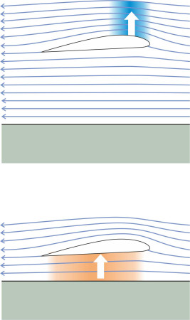
But in reality, the aerodynamic behaviour of a WIG is more complicated. As well heaving up or down, the fuselage can pitch back and forth. But unlike an aircraft, the two motions are coupled. The reason is that the location of the lift force acting on the wings changes with the flying height [34]). Before take-off, the wing is supported largely by increased pressure underneath, and the centre of lift lies well aft of the leading edge. At the other extreme, if the wing were to rise above the surface effect zone, it would be supported mainly by negative pressure or suction on the upper surface, with the centre of lift at a position roughly \(25\%\) of the wing chord from the leading edge. Consequently, as the craft climbs away from the water surface, the centre of lift moves forwards and the craft tends to pitch nose-up (figure 32). Nose-up trim in turn brings about a more rapid rate of climb. Conversely, any loss of height tends to lead to a nose-down trim that in turn increases the rate of descent [36].
Figure 32
Either way, any change in height tends to be magnified, a form of divergent instability that can pose a severe challenge to pilots [26]. There is a narrow margin for error. When flying in a headwind, a gust can make the craft rear up suddenly, and over-correction can make it plunge down again out of control. Because of this inherent instability, the early Russian ekranoplans with their rectangular wing planform needed careful adjustment of the booster angle, elevators, and wing flap setting during the transition from take-off to cruising, all in the correct order [38] [23]. Many crashed during testing, for example the SM-1, the SM-5, the KM, and the Orlyonok [5]. Although accounts differ, it seems that the KM pitched nose-down into the water and sank because the pilot couldn’t counter the dive quickly enough. Although the crew survived, the vessel was never recovered. More recently in the year 2000, a Chinese vessel, the Swan, reared up alarmingly and nearly flipped over backwards during a demonstration run, but the pilot recovered control and no-one was injured [25].
More recently, through a combination of theory and experiment, engineers have discovered wing configurations that make the ekranoplan easier to handle because the centre of lift doesn’t move greatly when the craft climbs or descends. During the 1960s, Lippisch pioneered a reverse delta planform that is remarkably stable and well suited to smaller craft flying at relatively modest speeds (figure 33) [35]. The prototype X-113 cruised at 80 km/h. Other machines have followed a similar pattern. The wings droop downward from root to tip (a feature known as anhedral in the aircraft world) but the wing tips are turned upwards to allow for heeling in turns and to provide greater stability in roll [26]. As with earlier machines, the tailplane is located high above the stern so it’s not disturbed by the wing slipstream and as far as possible lies clear of the surface effect zone.
Figure 33
Operations
Given a stable aerodynamic configuration, an ekranoplan can carry people and goods at 200 km/h or more. It is extremely fuel-efficient. The question is, can it replace the more conventional ships that are found across the oceans of the world today? Because it moves at such a high speed, the ekranoplan is not very manoeuvrable. Unable to bank as steeply as a conventional aircraft, it can’t develop the centripetal force needed to hold a tight curve. Hence it can’t navigate safely in crowded waters, because the pilot can’t see other vessels in time to steer around them, nor can they get out of the way. An ekranoplan must therefore operate as if invisible to other craft, by maintaining a minimum separation of 1-5 km depending on speed [32]. Finally, specialists have questioned whether a WIG can cross the Atlantic or Pacific Ocean in the same way as a conventional ship. With large wings, it might be able to cruise over a rough sea, but it couldn’t safely land on it in an emergency [39].
Conclusion
In this Section we have met some radical ideas for marine transport, vessels that can travel much faster than a conventional ship. Hovercraft first appeared over fifty years ago and have benefitted from a great deal of development since. You would imagine that by now, they would be in widespread use as passenger ferries for example, maybe even rivalling aircraft as the quickest way to get from one coastal area to another. But this is not the case. In Britain, where it once dominated the market for cross-channel ferry services between the UK and mainland Europe, the hovercraft was overtaken by the hydrofoil. Both were subsequently eclipsed by the opening of the Channel Tunnel and a shift in the market towards cheaper types of vessel. By the end of the millennium there were only about 2000 hovercraft in existence world-wide ([11]. Meanwhile, sidewall vessels evolved in a different direction: designers abandoned aircraft technology, replacing the expensive and vulnerable gas turbines with more robust diesel engines and waterjet propulsion. But they remain a niche market, largely devoted to military service.
Finally, the collapse of the Soviet Union brought the development of large WIG vessels to a halt. At the time of writing only two hundred or so have been built [33] [6], and no passenger services are currently in operation. Instead, a comparatively simple kind of vessel with a more conventional hull form, the wave-piercing catamaran, has come to dominate the fast ferry market, and later in Section M1508 we’ll try to understand why.
Appendix: Power requirements for a plenum chamber hovercraft
This method of working out the power requirement is based on [9] with a simplified notation. For a plenum chamber hovercraft the lift \(F\) is equal to the excess pressure \(p\) within the plenum chamber times the plan area \(A\), and at equilibrium exactly counterbalances the weight of the craft \(W\) so that
(12)
\[\begin{equation} W \quad = \quad pA \end{equation}\]We’ll denote the velocity of the escaping air by \(v\), assumed uniform throughout the escaping air stream. Assume also that the transition of air from inside the plenum chamber to the atmosphere outside can be framed in terms of Bernoulli’s equation for an incompressible fluid moving along a stream tube between two locations:
(13)
\[\begin{equation} p_{1} + \frac{1}{2} \rho {v_{1}}^{2} \quad = \quad p_{2} + \frac{1}{2} \rho {v_{2}}^2 \end{equation}\]where \(\rho\) is the density of the fluid, \(p_1\) the initial static pressure, \(v_1\) the initial velocity, \(p_2\) the final static pressure, and \(v_2\) the final velocity. Here we put \(p_{1} = p\), \(v_{1} = 0\), \(p_{2} = 0\) and \(v_{2} = v\), so that
(14)
\[\begin{equation} p \quad = \quad \frac{1}{2} \rho v^{2} \end{equation}\]and therefore
(15)
\[\begin{equation} v \quad = \quad \sqrt{\frac{2p}{\rho }} \end{equation}\]The air flow \(Q\) that must be supplied to sustain the cushion is equal to the volume of air escaping from the chamber per unit time. This equals the velocity times the cross-sectional area of flow escaping under the rim. With a ground clearance equal to \(h\) and perimeter \(l\) this cross-sectional area is just \(hl\), but there is some loss owing to the curved path of the streamlines around the lip which we account for by inserting a dimensionless ‘flow coefficient’ \(\phi\) whose numerical value lies between 0 and 1 depending on the angle \(\theta\) of the lip relative to the horizontal. Thus:
(16)
\[\begin{equation} Q \quad = \quad \phi \ \times \ hl \ \times \ v \end{equation}\]which after substituting for \(v\) via equation 15 becomes [9]:
(17)
\[\begin{equation} Q \quad = \quad \phi hl \sqrt{\frac{2p}{\rho }} \end{equation}\]The power \(P\) needed to sustain the cushion is equal to the pressure \(p\) times the flow \(Q\), so
(18)
\[\begin{equation} P \quad = \quad \phi hl {p}^{\frac{3}{2}} \sqrt{\frac{2}{\rho }} \end{equation}\]Acknowlegements
Figure 09: Photo of the French SNCF Sedam N500 Naviplane, posted at http://poduszkowcem.pl/wp-content/uploads/2017/08/poduszkoiwiec-sedam-n500a-min.jpg (accessed 12 May 2021).
Figure 15: Photo of the Pioneer Mk 3.1 by kind permission of Ross McLeod of Airlift Hovercraft, Alberton, Queensland, Australia, 16 November 2015.
Figure 16: Photo by Andrew Berridge of the SR.N4 Mountbatten Class hovercraft taken on its last day of service on 01 October 2000, posted at https://commons.wikimedia.org/wiki/File:SRN4_Hovercraft_Mountbatten_Class.jpg (accessed 14 November 2015).
Figure 24: Photo of the Caspian Sea Monster reproduced from the Old Machine Press web site, with the kind permission of William Pearce.