© Wartsila
F.1513
Propellers
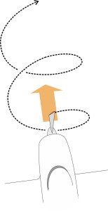
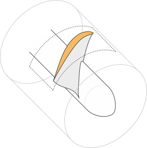
You are alone in a boat in the middle of Crocodile Lake. The wind has dropped, the hull is leaking, and the boat isn’t moving because the outboard motor has broken down. How to get to the shore? There are no oars and you dare not put your hand in the lake, but there is an empty plastic bag in the bilges. Maybe you could use it to scoop up some bilge-water and drive the boat forward by hurling it astern. It may seem far-fetched, but this is essentially what a propeller does. A propeller can’t grip the water in the same way as a car tyre grips the road, but it can apply a force to it, and although the water yields and moves astern, the force can be sustained as long as there is a continuous supply of water to act on. Curiously, the blades apply this force by moving sideways. To be more precise, they circulate around the propeller shaft like miniature wings, cutting diagonally through the fluid and tracing out a helical path at a speed much greater than the boat’s forward speed. An aircraft propeller works in the same way (figure 1). In this Section, we’ll see how the blades create ‘lift’ that lowers the pressure in the fluid immediately upstream and hauls the fluid towards them. This creates an equal and opposite reaction that draws the vehicle forward.
Figure 1
Turbo-machines
Propellers belong to a class of devices called ‘turbo-machines’ [6] [7]. Turbo-machines are rotating devices that interact with fluids, and they fall into two groups. Those in the first group operate like windmills, extracting energy from the fluid to use for various purposes such as generating electricity. We’ll call them turbines. Picture the windmill as a rotating disc, with pieces cut out of the disc to leave four sails arranged at equal intervals around the circumference and set at a slight angle to the plane of the disc. When the wind blows, a stream of air passes through the disc and the air particles apply pressure to the sails, forcing them to rotate. Devices like a hair dryer belong to the second group. They function in the opposite sense: driven by an engine, they pump energy into the fluid, lowering the pressure upstream and forcing the particles into motion. Although we don’t normally refer to it as such, a ship’s propeller is a kind of pump, and so is an aircraft propeller. Both project fluid aft in order drive the vehicle forward.
Rotors and stators
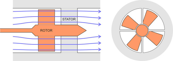
A turbo-machine has two essential parts: a rotating shaft, and mounted on the shaft, a set of blades arranged in the form of a disc or rotor that engages with the fluid. As well as the rotor, there may be a secondary element called a stator that doesn’t rotate, a set of blades also arranged in the form of a disc, but fixed in position upstream or downstream of the rotor. In the case of a turbine, its purpose is to control the flow of particles entering the rotor disc so they impact the blades in the right way and apply more pressure. Often, a turbo-machine will contain not just one but many rotor discs interleaved with stators at intervals along the shaft. In the case of a pump, a stator can prevent the fluid itself from revolving in the rotor slipstream (figure 2), motion that doesn’t contribute to thrust and represents wasted energy.
Figure 2
Pattern of flow through the machine
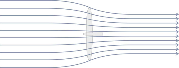
Propellers are axial flow devices. Fluid particles are drawn towards the propeller disc and follow a path that is broadly parallel to the shaft as shown on the left-hand side of figure 3. In some cases, there may be a duct or shroud surrounding the propeller that modifies the flow. For example, the fan attached to the front of a turbojet engine on a passenger airliner is enclosed within a duct. By contrast, most ship’s propellers and conventional aircraft propellers are open to the surrounding fluid. Nevertheless, we’ll assume the fluid particles that pass through the propeller disc are contained within a broadly cylindrical envelope. Its diameter may vary from place to place but the direction of flow remains broadly longitudinal. This cylindrical body of fluid is called the stream tube (figure 4). When modelling the flow pattern, the analyst will usually assume that the velocity is uniform over any given cross-section, although it will vary from one cross-section to the next.
Figure 3
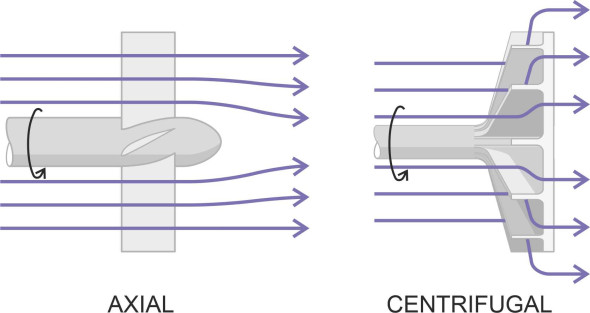
Figure 4
Not all kinds of turbo-machine work like this. For example, a rotary impeller forces the fluid stream to rotate, and under the action of centrifugal force, instead of moving parallel to the shaft the particles fly outwards in a radial direction as shown on the right-hand side of figure 3. Impellers are classed as centrifugal flow devices, and they are widely used on high-speed water craft. In fact a waterjet propulsion system will often contain a centrifugal impeller operating in series with an axial flow propeller, the whole being enclosed within a duct that runs from the water intake through to the exhaust at the stern. Such systems are dealt with briefly in Section M1405. Here, we’ll be concerned only with open, axial flow propellers.
Propeller configurations
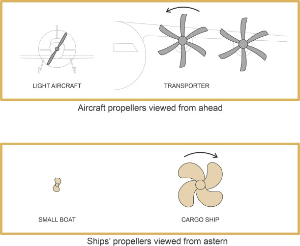
figure 5 shows two kinds of aircraft propeller seen from the front, and two marine propellers seen from astern. The aircraft propellers and the marine propellers have different shapes because they operate in fluids with different physical properties. In particular, air has a relatively low density, so to generate thrust, an aircraft propeller must spin faster and accelerate a relatively large volume of fluid per second. The propeller of a light aircraft typically revolves at between 1000 and 1500 rpm and carries two blades, which are relatively light and slender. The propellers of a heavy aircraft such as a cargo transporter have to work harder, which implies an even higher speed of rotation, a larger overall diameter, and four or more blades per propeller. The blades are wider, thinner and stronger than those of a light aircraft. Also, to postpone the onset of supersonic shock waves, they are shaped differently at the tip.
Figure 5
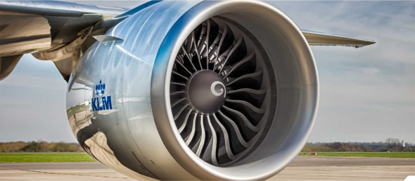
By contrast, the ‘propellers’ that power a typical passenger jet are more like fans, each having a relatively large number of blades enclosed within a shroud or duct usually at the front of the engine pod (figure 6). Driven by a jet engine, the fan revolves at over 3000 rpm, and although the engine produces a high-speed exhaust, it’s the fan that delivers most of the thrust. As we’ll see elsewhere in this web site, the duct guides the air flow and modifies the fan’s aerodynamic behaviour, which makes the fan more efficient in energy terms and also helps suppress noise.
Figure 6
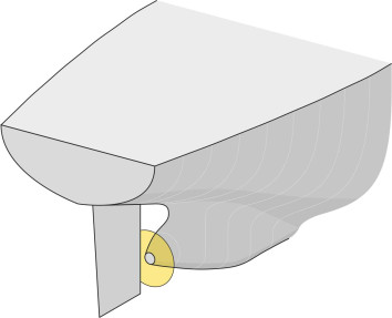
Although it works on the same principle, a ship’s propeller operates in a fluid that is 800 times more dense than air, so it doesn’t need to ‘pump’ the same volume of fluid through the disk per second to attain a given level of thrust. Hence the propeller runs more slowly, typically around 100 rpm in the case of a cargo vessel [8], and its diameter is smaller in relation to the size of the vehicle. Also, it occupies a different position: it can’t be mounted in front of the bow, or cantilevered out to either side where the blades might collide with rocks or underwater debris. Instead, as shown in figure 7, it is positioned in a confined space close to the hull plating under the stern.
Figure 7
The blade geometry
Most ships’ propellers rotate clockwise when viewed from behind, and the same is true for aircraft propellers. It’s a convention that possibly derives from carpentry: to drive a screw forward into a piece of wood, you turn it clockwise. But what really matters is the size and shape of the blades, which determine the lift force that propels the vehicle forward. So let’s look more closely at a typical blade.
Profile
We’ve seen that a ship’s propeller is comparatively small in relation to the vehicle body, and that the blades are shaped differently from those of an aircraft propeller, with a wider chord. The wider chord helps to postpone cavitation. When the pressure on the upstream face of a ship’s propeller falls below the vapour pressure of the fluid, bubbles will form close to the blade surface. This reduces the hydrodynamic efficiency of the blade, and as the bubbles move away downstream to a region of higher pressure, they implode, sending shock waves through the water. As described in Section M1410, the shock can damage the blade surface. Hence the blades of a ship’s propeller are typically designed with a large surface area in order to spread the load and avoid extreme pressure variations. You’ll notice how the blades tend to overlap when viewed from behind so that compared with an aircraft propeller, there is relatively little space between them. They may also be ‘swept back’ in the same way as the wings of a high-speed aircraft, so that the leading edge, instead of projecting radially from the hub in a straight line, follows a spiral curve.
Cross-section
The width or chord of each blade varies from the blade root to the tip, and the angle of the blade surface varies too. Imagine the blade divided into short elements each positioned at a particular radius \(r\) or ‘station’. At any given station, the cross-section resembles that of an aircraft wing, and in fact the blade cross-sections are often based on standard wing profiles developed within the aircraft industry. However there is a subtle difference. Because the blade rotates around a fixed axis, its cross-section is defined on a cylindrical surface as shown in figure 8, and the cross-sectional profile differs slightly from the one you’d observe if you sawed through the blade along a flat plane. An analyst will usually assume that the fluid particles move within this cylindrical plane as they flow around the blade cross-section, although in practice, the fluid velocity may have a radial component too.
Figure 8
Pitch
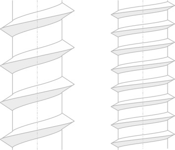
Each blade is fixed at an angle to the plane of rotation, and this angle determines how aggressively the blade attacks the surrounding fluid. To grasp the geometry, we can view the propeller as a screw being driven into a block of wood. A carpenter’s screw has a ridge that winds around its shaft many times: a helical thread whose pitch is defined as the distance between successive turns of the ridge measured parallel to the shaft axis. It tells you the distance that the screw will move through the wood when turned through 360 degrees. The pitch angle \(\theta\) is the angle made by the ridge with the shaft centreline when viewed from the side as shown in figure 9. For some screws, the angle is relatively large as shown diagrammatically on the left-hand side of figure 10. They are said to have a coarse pitch,whereas in other cases the angle is flatter; they have a fine pitch and don’t move as far.
Figure 9
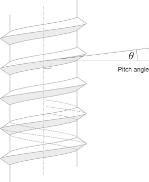
Figure 10
Each blade of a propeller can be likened to the ridge on a carpenter’s screw, forming part of a helical thread. In fact there are several ridges, one for each blade. But the ridge is much higher than a screw thread, projecting outwards a distance \(R\) from the shaft centreline, \(R\) being the radius of the propeller disc. Most of the ridge is cut away and doesn’t form a continuous spiral round the shaft. So the question arises, how to define the ‘pitch’. To answer this, we’ll imagine the propeller being screwed into a solid but pliable material like butter, and focus attention on a single blade. We hope to judge from the angle of the blade how far it will move forward during a complete revolution, in other words, the pitch. But the angle varies along the length of the blade so we’ll have to choose a location that is somehow representative of the whole. We’ll start at the tip of the blade, denoting its angle by \(\theta_R\), and track its path for one revolution. It follows a helix of radius \(R\) as shown in figure 11.
Figure 11
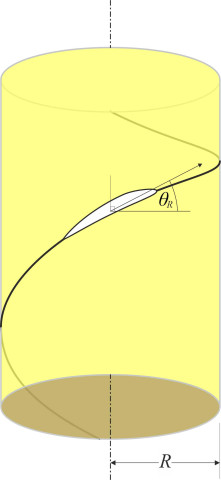
Figure 12
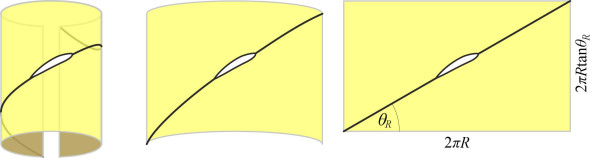
Now imagine this path projected onto a paper tube wrapped around the helix, with the trace drawn on the outside of the tube. If we unroll the paper and spread it flat on the desk we’ll see a straight line at an angle \(\theta_R\) to the axis as shown in figure 12. The circumference of the tube is \(2\pi R\) and in one revolution we expect the blade tip to move forward a distance given by:
(1)
\[\begin{equation} p_R \quad = \quad 2 \pi R \tan \theta_R \end{equation}\]Typically, the pitch angle at the tip of a ship’s propeller lies between \(15^{\circ}\) and \(20^{\circ}\), and the pitch itself is of the same order as the propeller diameter. For an aircraft propeller the pitch angle is somewhat less. In figure 11 and most of the remaining Figures in this Section, the pitch angle is exaggerated for clarity.
The twisted blade
equation 1 will form the basis for our definition of geometric pitch, but there is a difficulty, in fact two difficulties. The first has to do with the blade cross-section. From its curved profile, it’s not immediately obvious how to define the ‘angle’ of the blade. In principle, we are looking for a reference line that indicates the direction along which the blade tip must travel in order to avoid generating lift, in other words, the ‘zero lift line’. Unless we know the angle of this line, we can’t be sure exactly what path the blade will follow as it cuts through the butter and hence there is some uncertainty attached to our estimate of the pitch angle \(\theta_R\). It is common practice to take the chord line as the reference line, this being the straight line that joins the foremost point on the leading edge and the aftmost point on the trailing edge as shown in figure 13.
Figure 13
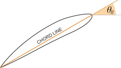
Figure 14
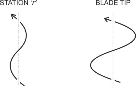
The second problem is that the blade is twisted. To understand the consequences, we’ll carry out another thought experiment, this time focussed on a different part of the blade, an intermediate station at radius \(r\) somewhere near the root. Call it ‘station \(r\)’. Now imagine all the other parts of the blade are removed to leave this small element slicing through the butter. On the left-hand side of figure 14 we see the helical path that it follows during one complete revolution. The helix for the blade tip is shown on the right for comparison.
Figure 15
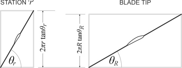
Now let’s unroll the two cylinders. The trace for station \(r\) appears on the left-hand side of figure 15: the helix angle \(\theta_r\) is greater than the helix angle \(\theta_R\) of the blade tip because it is closer to the root. However, what matters is the distance \(p_r\) it moves forward in one revolution, and this distance is given by
(2)
\[\begin{equation} p_r \quad = \quad 2\pi r\tan \theta_r \end{equation}\]The unrolled trace for the blade tip is shown on the right for comparison. For this particular propeller, station \(r\) has moved forward a little further than the tip: the manufacturer has shaped the blade in such a way that the angles \(\theta_r\) and \(\theta _R\) are not consistent, so the two stations yield slightly different estimates of the pitch. We could of course demand total consistency, so that no part of the blade is ‘fighting’ any other and causing unnecessary friction. The condition for geometrical consistency is
(3)
\[\begin{equation} r \tan \theta_r \quad = \quad R \tan \theta_R \qquad (0 < r < R) \end{equation}\]However, since the fluid flow conditions vary along the blade, there may be good hydrodynamic reasons for configuring the geometry in a way that violates equation 3. If so, how might we specify the pitch in terms of a single number? The answer is to work out an average figure across all stations, and there is a recognised procedure for doing this [2]. There is also an alternative procedure that ignores the geometry and relies on empirical measurement instead. Suppose we put an aircraft propeller in a wind tunnel and blow air towards it at a fixed speed. Using an external source of power, we set the propeller rotating and adjust the speed of rotation until it is producing zero thrust. Then the distance that the air moves along the tunnel and through the propeller disc during one revolution defines the ‘experimental mean pitch’ [5].
Blade motion through the fluid
For any propeller, the geometric pitch \(p\) is a fixed quantity. Defined by the shape of the blades, it determines the propeller’s behaviour when screwed into a solid material. But when immersed in a fluid, like a car tyre on an icy road, it can’t grip the fluid properly. It slips: the distance the propeller actually moves through the fluid per revolution will vary from moment to moment and is rarely equal to \(p\). We call the actual distance the advance. You would expect the advance per propeller revolution to be the same as the distance covered by the vehicle itself: if an aircraft travels \(x\) m relative to the surrounding air mass, then so does its propeller. But this is not necessarily true for a ship, because the water may slow down before reaching the propeller owing to friction with the hull surface. That’s why we measure the advance, together with the advance velocity \(V_\text{a}\), relative to the fluid in the region of the propeller rather than relative to the ocean beyond. In fact, \(V_\text{a}\) is measured slightly upstream, because the blades themselves cause the fluid to speed up as it passes through the disc.
Advance
Because the propeller ‘slips’, the advance is nearly always less than the pitch, and it’s this difference that enables the propeller to do its work. To understand how, it will help if we simplify the geometry and for the time being, ignore the variation in pitch angle along the length of each blade. Instead, we’ll picture the blade as a plate mounted on a rod perpendicular to the shaft as shown in figure 16. The plate is small and flat, and it has a uniform pitch angle \(\theta\). As it advances, the plate traces out a helical path whose angle we’ll call the advance angle, denoted by \(\phi\). It is usually less than \(\theta\), and as shown in figure 17, the difference \(\theta - \phi\) determines the angle of attack \(\alpha\).
Figure 16
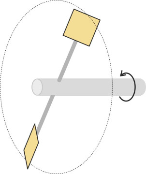
Figure 17
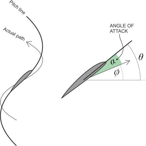
For convenience, we’ll picture the device as an aircraft propeller, but the same principles apply to a marine propeller as well. During a flight, the advance per revolution will vary from moment to moment over a wide range. At the instant when the pilot starts the engine, there is no air flowing through the propeller disc and the advance is zero. Consequently, the angle of attack is very steep, and momentarily, the blades ‘stall’. The advance increases when the aircraft picks up speed and takes off; once it is cruising in level flight, the advance will rise to a value a little short of the geometric pitch. To maintain thrust, however, there must still be a modest, positive angle of attack.
Figure 18
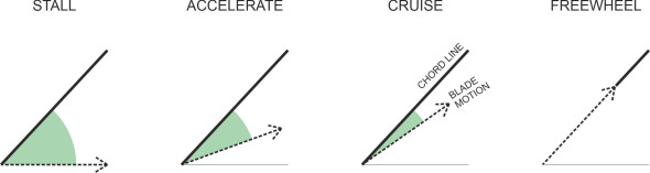
Towards the end of the flight when the aircraft begins its descent, the propeller doesn’t need to work so hard and the advance will increase further until it is almost equal to the pitch. If the advance were to rise to the same level as \(p\), the blades would slice through the fluid at zero angle of attack and produce no lift or thrust; in the same way, when a cyclist freewheels downhill, the pedals may be going round but the rider isn’t putting any pressure on them. Figure 18 illustrates all these events in sequence, from stall to freewheel.
Velocity vectors
Although the picture we have presented here is a simplified one, it reveals the chain of causation in the way a propeller operates:
- The advance is usually less than the pitch;
- the difference between the pitch angle and the advance angle fixes the angle of attack;
- the angle of attack, in conjunction with the velocity of the blade element relative to the surrounding fluid, determines the lift and drag acting on the blade;
- the lift and drag determine both the propeller thrust and the shaft torque needed to achieve it.
To progress to the next level, we must recognise that in practice, different parts of a propeller blade move at different speeds relative to the surrounding fluid, and the hydrodynamic forces will vary along the length of the blade. So in order to estimate the lift and drag it is generating at any moment, one must divide the blade into short elements and analyse each element separately. We’ll also change our frame of reference and picture the blade as stationary while the fluid moves past it (the surrounding fluid mass, the vehicle, and in fact the whole universe is now revolving around the propeller shaft).
Figure 19
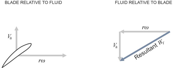
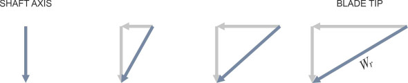
Let’s examine an element at radius \(r\). For any given blade cross-section, we can use standard aerofoil theory to estimate the lift and drag if we know the angle of attack and the relative velocity of the fluid flow, which we’ll denote by \(W_r\). In figure 19 the velocity vector \(W_r\) is resolved into two components: an axial component, and a circumferential component. Assume that the axial component is numerically equal to the advance velocity \(V_\text{a}\) of the propeller relative to the approaching fluid. On the understanding that it’s aligned in the opposite direction we’ll write informally:
(4)
\[\begin{equation} \text{Axial velocity component} \quad = \quad V_\text{a} \end{equation}\]What about the circumferential velocity component? For the moment we’ll take this as the speed at which the station is orbiting the shaft, so that
(5)
\[\begin{equation} \text{Circumferential velocity component} \quad = \quad r \omega \end{equation}\]where \(r\) is the radius and \(\omega\) the angular velocity of the propeller disc in radians per unit time. (In reality, as the fluid in the stream tube passes through the propeller disc, the whirling blades make it spin, so the true value of the tangential velocity is less than \(r \omega\), an issue that we’ll postpone until the next Section.) We now have two velocity components at right-angles as shown in figure 19, so we can evaluate the resultant \(W_r\) as the hypoteneuse in the vector diagram:
(6)
\[\begin{equation} W_r \quad = \quad \sqrt{{V_\text{a}}^{2} + r^{2} \omega^{2}} \end{equation}\]The formula suggests that \(W_r\) varies along the blade, rising steadily with \(r\) from root to tip. Its direction changes too, as shown schematically in figure 20.
Figure 20
At this stage, you’ll be getting the impression that propeller dynamics is a complex subject, and you’d be right. In the previous Section (F1518), we saw that the the advance velocity \(V_\text{a}\) is not necessarily equal to the vehicle’s speed \(V\). And there are two more complications to take into account. First, we have treated the propeller action as a process that takes place in two dimensions, focussing on the axial and circumferential components of fluid motion relative to the blade as set out in equations equation 4 and equation 5. In reality there is a third component acting along the blade as well [4]. The influence of the radial component is small and is usually ignored. Finally, the paths of the fluid particles do not follow the simple geometry of the stream tube shown earlier in figure 4. They can’t because the body of the vehicle itself gets in the way. In the case of an aircraft, depending on where the propeller is located, the engine pod or the fuselage will partly block the exit flow downstream. By contrast, a ship’s propeller is immersed in the vessel’s wake as shown earlier in figure 7. We’ve already seen how friction with the hull surface slows down the fluid upstream of the propeller disc, and as explained in Sections F1518 and M1410, the propeller and hull interact in other ways too.
Lift, drag, and thrust
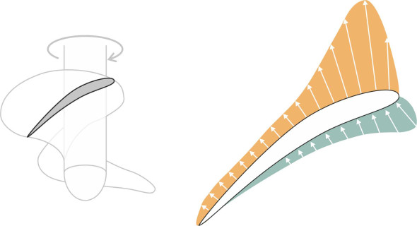
The forces acting on a propeller blade are strongly influenced by the blade cross-section. The lift arises from the difference in pressure between the two faces: the convex forward face causes the fluid to accelerate and its pressure to fall. On the aft face the pressure rises, but it contributes a relatively small proportion of the total thrust. To put it crudely, the propeller sucks fluid towards it, and what happens on the aft face is relatively unimportant. Figure 21 is a sketch of the approximate pressure distribution over the surface of a marine propeller blade.
Figure 21
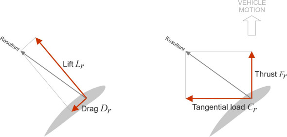
There are several methods for estimating the pressure distribution based on aerofoil theory, ranging from theoretical ‘lifting line’ methods adapted for use with propeller blades, through to simulation models using computational fluid dynamics [1] [3]. We’ll examine some of them elsewhere in Section A1716 in the context of aircraft flight. To prepare the way, let’s look briefly at the geometry. Assuming we can estimate the lift and drag forces at each station along the propeller blade, we’ll need to understand how they translate into thrust. Consider a short length of blade at radius \(r\): as before we’ll label it ‘station \(r\)’. Figure 22 shows the forces acting on it, namely the lift force \(L_r\) acting at right-angles to the chord line, together with a drag force \(D_r\) parallel to the chord line. Neither is aligned with the direction in which the vehicle is moving, and to see how they contribute towards the thrust, we must re-map them into the two components \(F_r\) and \(C_r\) as shown on the right-hand side of the Figure. The symbol \(F_r\) represents the thrust developed by the blade element parallel to the shaft, while \(C_r\) represents the circumferential load, which applies a torque to the propeller shaft at lever arm \(r\). This torque represents a load that the engine must overcome.
Notice that the lift vector \(L_r\) contributes both to the forward thrust and to the circumferential load. The relative values of these two contributions are determined by the pitch angle \(\theta\). Ideally, the pitch angle will be small so that the lift vector drives the vehicle forward rather than resisting the rotation of the propeller, but this can’t be done at stations close to the propeller axis, where the angles are less favourable and the greater part of the lift force is wasted. In fact, most of the useful work is done by the outer section of the blade relatively close to the tip, and the centre of lift is commonly assumed to lie at a radius in the region of \(0.7R\).
Figure 22
Where next?
In this Section, we have tried to explain some of the forces acting on a propeller blade. In the next Section, we’ll broaden our scope and see how the blades influence the motion of the surrounding fluid as it approaches the propeller disc, and afterwards downstream. It turns out that the propeller dissipates energy into a fast-moving jet that plays no part in driving the vehicle forward, and this has consequences for the propeller’s efficiency as a device for converting engine power into forward motion. Later, in Section M1410, we’ll look at marine propellers specifically and how they behave at sea.
Acknowledgements
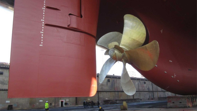
Photo on leading page: Wärtsilä propeller fitted to a vessel under construction in 2015 in the Hantong Ship Heavy Industry yard in China. Source: https://safety4sea.com/tms-tankers-selects-wartsila-propellers/ (accessed 02 May 2020).
Figure 6 Photo of fan jet: KLM Blog site https://blog.klm.com/how-time-flies-100-years-of-klm/, accessed 08 January 2020.