M.1405
Propeller installations
A ship won’t perform well if the propeller doesn’t. A conventional propeller works best when it is moving forward through the water at a certain speed. We saw in Section F1518 that its efficiency rises with advance velocity to a fairly sharp peak, at which point the propeller converts the maximum proportion of engine power into forward thrust – and by implication, wastes the least possible amount of fuel. The efficiency falls very quickly thereafter. This is fine for a vessel that is meant to travel for long distances at a fixed cruising speed, but in the fiercely competitive shipping world, a ship that can work economically over a wide range of operating conditions has a commercial advantage, and this calls for more sophisticated forms of propeller. In this Section, see how one can channel the flow of water through the propeller disk to make it do things that a conventional propeller cannot.
Variations on the standard propeller
If you change the wheels on a car, provided the new ones have the same diameter as the old ones, you don’t expect the car to go any faster or slower, at least not very much. When a wheel turns through a single revolution, the car moves forward a distance a distance more-or-less equal to the circumference of the tyres. Ships are different. Owing to the complex nature of fluid flow around the propeller blades, there is ‘slippage’ in the system because the propeller’s rotational speed and the vessel’s forward speed are not mechanically linked: there is an extra degree of freedom so that in principle at least, there is scope for modifying the shape of the blades to extract more thrust from a given power input, or to reduce energy losses over a range of operating speeds.
Controllable pitch propellers
We’ll start at the lower end of the speed range. Most cargo ships and most passenger vessels are powered by diesel engines that are designed to work at a particular operating speed. You can’t speed them up or slow them down. For a ship to move slowly over an extended period of time, the engine must be disengaged from the propeller shaft at frequent intervals, which results in a ‘stop-start’ motion that potentially wastes fuel. Otherwise, the power must be routed through a gearbox that will enable the propeller to turn at a lower rate. A ship’s gearbox is heavy, expensive, and takes up a good deal of room. Also, a gear change itself takes time.
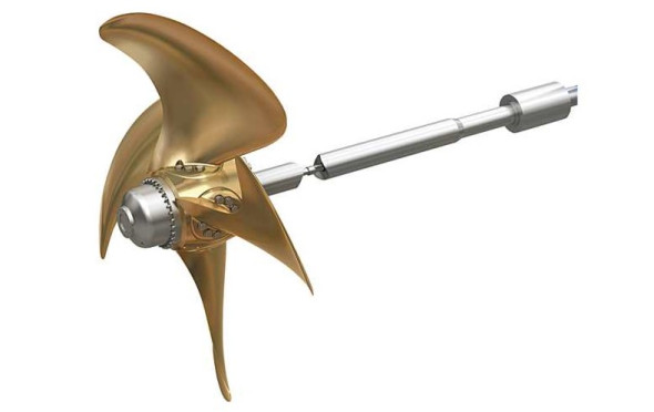
Under these circumstances, a controllable pitch propeller as shown in figure 1 works better than a conventional propeller: the blades are mounted on swivelling bearings so their pitch can be altered while the ship is in motion [15]. This enables the captain to ‘feather’ the blades and slow down without disconnecting the engine, so the ship can manoeuvre in a confined space. In fact, some ships spend a significant proportion of their working lives travelling slowly; for example tugs, which need to exert considerable thrust while manoeuvring larger vessels in and out of port, and fishing vessels such as trawlers, that drag their nets at 4 – 6 knots then head for home as quickly as they can to land their catch [9].
Figure 1
There are two other manoeuvres that make heavy demands on a conventional propeller. The first is moving astern under power, a manoeuvre frequently carried out by ferries as they ease in and out of harbour. The second is an emergency manoeuvre: when a collision seems imminent, the captain may want to use the propeller as a brake. In either case, the propeller’s direction of rotation must be reversed. The process takes time and it requires a complicated gear mechanism (in the case of a steam turbine, it requires a completely separate power unit). In contrast, one can reverse the thrust of a controllable pitch propeller by reversing the pitch of the blades while the drive shaft continues to run in the normal direction. Note, however, that a single, controllable pitch propeller turns in the opposite direction to a conventional propeller. The drive shaft is usually set up to run anti-clockwise rather than clockwise, because in an emergency, all ships are expected to steer to starboard. With a conventional right-handed propeller, this happens automatically when the master executes a ‘crash stop’ by reversing the direction of rotation – it’s caused by the paddle-wheel effect. However, for a ship with a controllable pitch propeller, in an emergency stop the direction of rotation of the shaft is not reversed, so if the propeller were right-handed the ship would tend to turn to port [2] [5]. This is a topic we’ll re-visit in Section M0415.
The Kappel Propeller
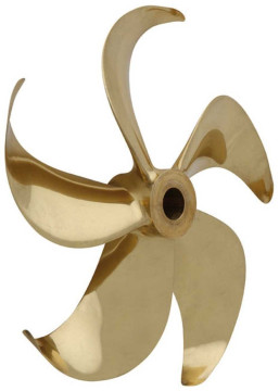
A problem in the design of an aircraft wing is that air ‘leaks’ around the wing tip from the high-pressure area below to the low-pressure area above, which partly neutralises the pressure difference and thereby diminishes the lift. As explained previously in Section M1716, the same happens with each of the ‘wings’ attached to a hydrofoil boat; also the curved path followed by leaking water particles results in a vortex that trails behind the tip of the foil and dissipates energy. The same applies to a propeller blade. An obvious way to improve efficiency would be to lengthen the blade, but this can’t easily be done with a marine propeller for the reasons mentioned earlier – there must be a minimum clearance between the tip and the underside of the hull. Some year ago, the Danish naval architect and marine engineer Jens Kappel borrowed a solution from aircraft design [26]. Each blade of a Kappel propeller incorporates a winglet - a small extension very roughly at right-angles to the plane of the blade (figure 2). It discourages fluid from spilling around the tip from the compression to the suction side, and thereby reduces the strength of the tip vortex without compromising the clearance gap [1].
Figure 2
Cavitating propellers
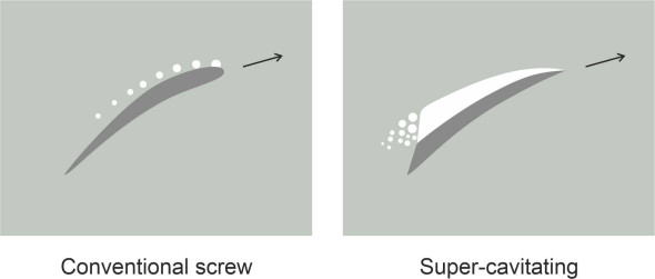
Now for the other end of the speed range. If you want to make a ship go fast, a conventional propeller falls short because its performance is limited by cavitation. The solution is a high-speed propeller whose blades are specially shaped so that the vapour cavity stretches across the whole suction surface, with liquid water in contact only on the aft face. This reduces friction and prevents bubbles from collapsing and damaging the blade material [4] [22]. A propeller of this kind is known as a super-cavitating propeller or ‘Newton-Rader’ propeller after the two researchers who invented it [11]. Nowadays the blades have a sharp leading edge and a kind of chamfer or ‘cupping’ at the trailing edge [12], as shown in figure 3.
Figure 3
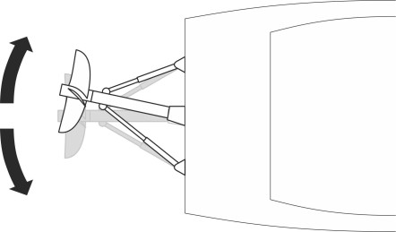
The efficiency of a cavitating propeller seems to be less than that for a sub-cavitating propeller, typically in the range 60 - 70\(\%\) [21], but engineers have improved matters by raising the propeller shaft to surface level so the blade disk is half out of the water, and located behind the stern rather than underneath (figure 4). A propeller of this kind is known as a surface-piercing propeller or ‘cleaver’ propeller. Being exposed to the atmosphere, the disk is ‘ventilated’, meaning that when it enters the water after passing through the twelve-o’clock position, each blade draws a bubble of air into the cavity on the suction face. The air bubble compresses as the cavity shrinks and prevents a violent collapse [12]. A cleaver propeller is usually made from stainless steel. Its diameter is not limited by the proximity of the hull and hence it can be designed to provide greater thrust than would be possible with a conventional screw. It can drive a boat at well over 100 knots [20], and is smooth in action with little vibration [12]. As shown in figure 5, if an articulated jointed is added to the drive shaft together with a pair of hydraulic rams to swivel the propeller disk, it can steer the boat as well.
Figure 4
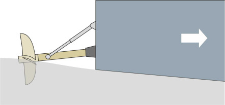
Figure 5
Propellers that steer
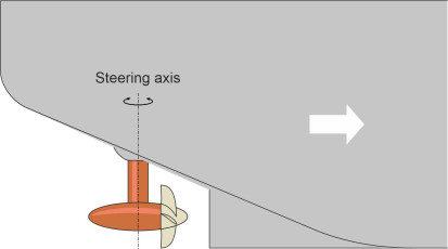
In confined surroundings, a swivelling propeller makes a ship easier to handle because it can swing the stern to port or to starboard when it is travelling too slowly for the rudder to have much effect, which, of course, is what an outboard motor does. The equivalent for a larger craft is the so-called ‘pod’ drive. As shown in figure 6, it consists of a propeller attached to a steerable nacelle mounted below the stern that contains either an electric motor or a transmission shaft geared to the ship’s engines. Such units are often installed on passenger cruise ships that berth in small or crowded ports. Some ships have multiple pods, for example two at the bow and two at the stern. The hull must be specially shaped to accommodate the units and the crew need special training [10] to avoid aligning the slipstream of one pod with the upstream face of another, which can cause damage. A much simpler concept is the ‘thruster’: an auxiliary propeller that is fixed with its shaft at right angles to the direction of motion so it provides lateral thrust. The most common type is a bow thruster fitted inside a tunnel that passes laterally through the hull below the waterline at the bow. Some ships have additionally a thruster at the stern. We’ll return to both types of device in Section M0505.
Figure 6
Ducted propellers and waterjets
As explained earlier, the fluid passing over the aft face of a propeller blade can take a short cut, ‘leaking’ around the tip onto the low-pressure side, thereby limiting the blade’s thrust and compromising its overall efficiency. For over 50 years, engineers have tried to reduce tip losses and extract more thrust by enclosing the propeller in a tube or duct, the idea being to close off the escape route so the fluid is obliged to create lift at all stations along the blade. The duct itself creates friction, and the challenge is to ensure that the friction losses don’t outweigh the gain in thrust. There are at least two alternative configurations, the ducted propeller and the waterjet. Here we’ll try to explain how they work.
The ducted propeller
Variously described as a cowl, shroud or Kort nozzle, the ducted propeller is used for low-speed craft such as tugs and trawlers. The story of its development is a curious one. It began during the 1920s when the German authorities became concerned about the increasing erosion of canal banks caused by the wash from boat propellers. Owners were obliged to install ducts around their propellers to contain the wash. The problem attracted the attention of the aeronautical engineer Ludwig Kort, and led him to patent a tapered duct that has since been installed on many ships. Its diameter falls gradually from front to rear. The longitudinal cross-section of the ring resembles that of an aircraft wing with the convex or suction surface inwards (figure 7), and its effect is to generate a slipstream whose diameter is larger than that of an equivalent non-ducted propeller, and whose velocity is reduced. But as Ludwig Kort discovered, there is a further benefit: the nozzle itself increases the thrust. The increase comes from two sources. First, the curved profile accelerates the incoming fluid, and by increasing the speed at which it enters the duct it reduces the inlet pressure. The reduced pressure acts on the inner face of the duct, which is inclined towards the direction of motion, and produces a longitudinal force that augments the thrust from the propeller blades and may indeed account for 40\(\%\) of the total. Second, the duct prevents or reduces the ‘leakage’ of fluid around the blade tips, suppressing the tip vortex and reducing energy losses.
Figure 7
The Kort nozzle works best when the ship is travelling slowly [14], because at high speeds the shroud causes appreciable drag, and the reduced entry pressure increases the likelihood of cavitation. Other variants have since been produced that decelerate the entry flow and thereby reduce cavitation. Since this lowers the noise level, they are often used for military applications such as torpedoes and submarines [6]. When applied in combination with ‘stator’ vanes to reduce rotational losses, the decelerating configuration is sometimes referred to as a pump jet [14].
How waterjets work
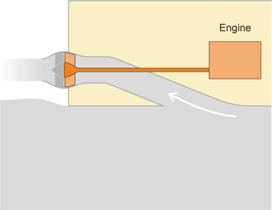
For many years, inventors have been experimenting with a device that carries this idea further, by extending the duct into a long, thin tube that curves upwards into the hull and extends aft to the transom, where the fluid exits above water level. The propeller is placed near the aft extremity. Such a device – known as a waterjet, draws in fluid from underneath the boat and pumps it out at the stern. The first practical example was created in 1931, and since that time, waterjets have been used in growing numbers to drive small and medium-sized craft intended to operate in situations where speed and manoeuvrability are vital [8] [13]. There is no drag-inducing machinery below the waterline, just an intake. Water passes diagonally upwards through the intake and travels via the duct to a pump that pressurises the fluid and forces it out at a high velocity like a jet engine or a rocket motor. The schematic layout is shown in figure 8. By pivoting from side to side, the exit nozzle acts as a rudder, and attached to the nozzle is a deflector plate that provides reverse thrust when needed [7] [12]. This gives the waterjet craft great manoeuvrability, and furthermore the pump can be designed so it is less liable to cavitation than a conventional propeller and is therefore capable of operation at higher speeds. You can find more details in [23].
Figure 8
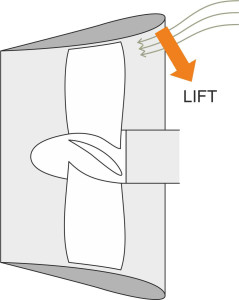
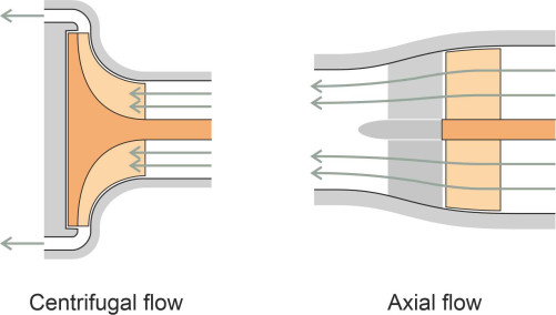
When a waterjet is fitted to a displacement craft or planing craft, the intake is located underneath, flush with the hull surface. This doesn’t work for a hydrofoil or a hovercraft, whose hull rises out of the water at speed, so the boat is provided with a ‘scoop’ or ram intake as shown in figure 9. The scoop delivers water to the pump, of which there are two main types: centrifugal and axial. The difference is shown diagrammatically in figure 10. The first type contains an impeller disc that whirls the incoming fluid around and throws it radially outwards; the centrifugal force drives up the fluid pressure at the outlet round the rim. By contrast the axial flow pump acts like a ducted propeller. The blades are shaped like those of a conventional ship’s screw and there is a stator located in the propeller slipstream. The propeller blades apply hydrostatic ‘lift’ that accelerates the fluid particles rearward, while the stator recovers what would otherwise be lost energy in the exhaust stream by counteracting the rotational movement induced by the impeller. Which type is best depends on how fast you want the boat to go [24]. Centrifugal pumps operate at lower speeds: they were the first to arrive on the scene because they were compact and relatively easy to make. Today, most pumps for larger vessels are ‘mixed’ in the sense that the fluid is taken through a combination of axial and centrifugal motions. In some cases there is an additional first stage: an inducer pump, shaped somewhat like a helical screw. Its purpose is to boost the pressure of the incoming water before it enters the ‘main’ pump, and thereby reduce the likelihood of cavitation. Inducer pumps were originally developed by the aerospace industry for use in rocket motors.
Figure 9
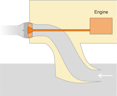
Figure 10
Waterjet performance
At first glance, the waterjet doesn’t satisfy the conditions for an efficient propeller. The momentum theory described in Section F1518 suggests that for maximum efficiency, the diameter of the streamtube should be as large as possible. For a waterjet, this implies a bulky and heavy casing, and in addition one might reasonably suspect a waterjet to be less efficient than an open propeller by virtue of the friction between the pumped water and the duct lining.
In practice, however, it appears that when travelling at the relatively high speeds for which waterjet units are typically designed, the loss of efficiency is small. There are two reasons for this. First, unlike a propeller, the waterjet pump is hidden inside the hull with no projecting shaft that would cause friction or appendage drag. Second, provided the intake is flush with the hull, a waterjet propulsion system can take advantage of a curious effect called wake ingestion. The effect can be explained by invoking simple momentum theory once more [16] [18]. First, imagine the waterjet system installed in a hydrofoil craft with a scoop intake suspended below the hull. The scoop is moving through still water, which enters the duct at a speed equal to the speed of the craft measured relative to the surrounding fluid. On reaching the impeller, the water accelerates and is ejected at high speed. It is the speed difference between intake and exhaust that determines the change in momentum of each particle of water and therefore the thrust developed by the unit.
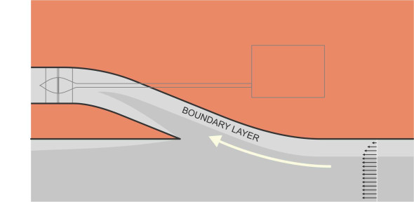
Now consider the same waterjet system installed in a conventional craft with the intake flush with the underside of the hull. The intake draws in fluid from the boundary layer. But this fluid is already moving in the same direction as the boat. Before entering the aperture, it is dragged along through friction with the hull surface (figure 11), and relative to the hull, it enters the duct more slowly than it would in the case of the hydrofoil scoop. Let’s assume the waterjet accelerates the fluid through the same velocity increment as the hydrofoil scoop so the system develops the same thrust. By comparison, there is less kinetic energy wasted in the exhaust stream because it exits at a lower speed. Hence the efficiency is greater - the engine uses less fuel to attain a given thrust - and it does so by exploiting the drag imposed by the vessel itself on the surrounding water! Together with reduced blade tip losses, wake ingestion makes the waterjet nearly as efficient as a conventional propeller, with a value typically within the range 65\(\%\) - 80\(\%\) [21]. Incidentally, aerospace engineers believe that the same effect could be exploited to boost engine thrust levels for a ‘blended wing’ aircraft [3].
Figure 11
To summarise, the waterjet works well at speeds up to 60 knots. Above this speed, cavitation becomes a nuisance [13] [25]. It produces relatively little vibration, which in turn reduces wear and tear on the engine and transmission, it can operate in shallow water, and it confers improved manoeuvrability including good acceleration and braking without the need for reversing gear. On the other hand, it is heavier than a conventional propeller.
Conclusion
Today, the design and manufacture of propellers is a high-technology business with links to the aerospace industry, and the pace of innovation seems to be increasing. The waterjet ‘inducer’ owes its origins to rocket science, and some propellers have ‘winglets’ of the kind used on the wings of jet aircraft. In addition, there are devices for manipulating the flow of water through the propeller disc in a way that increases the thrust or improves the propeller’s efficiency, such as the propeller boss cap fins shown in Figure 15 of the previous Section (M1410). There are also more radical devices that we haven’t described here; for example, those that emulate the swimming motion of a fish. Fish - at least some of them - can swim fast using relatively little energy, and the motion of their bodies creates less disturbance in the water than a conventional propeller. A machine capable of performing at this level would be useful to marine ecologists for deep-sea exploration, but building one poses a difficult engineering challenge. There have been few attempts to date, a noteworthy example being the RoboTuna, a replica blue-fin tuna constructed around an 8-link body and tail mechanism [19]. Reportedly [17], it has achieved an efficiency greater than 90\(\%\). However, at this point, we’ll leave the matter of propulsion altogether and return to hydrodynamics on a larger scale. In the next Section, we’ll be concerned with fluid motion around the ship’s hull.
Acknowledgements
Figure 1 Controllable pitch propeller by Kongsberg: https://www.kongsberg.com/maritime/products/propulsors-and-propulsion-systems/propellers/controllable-pitch-propeller/ (accessed 16 May 2021), copyright permission applied for.
Figure 2: Kappel propeller by MAN Diesel & Turbo, Motorship on-line magazine 30 March 2016, http://www.motorship.com/news101/industry-news/man-acquires-kappel-propeller-designs (accessed 16 May 2021), copyright permission applied for.