M.1015
Stresses and strains
Most of the objects around us are structures. They are made of solid materials and have a recognisable shape. An example would be the chair you are sitting on (if indeed you are sitting on a chair), maybe the laptop in front of you, and the pencil by its side. A skyscraper is a structure, and so is a canoe: each is built around a framework that gives it rigidity. Often the framework is hidden under the skin like the skeleton of an animal, while in other cases it forms an external casing, like a crab shell. But all structures are built up from components or members such as beams, struts, and plates, each of which carries a load of some kind. They are joined together and work cooperatively, enabling the structure to resist potentially destructive forces. No member is completely rigid, but will distort a little under load. In this Section, we’ll describe such behaviour as elastic, a technical term that has nothing to do with rubber bands, meaning instead that the deflection is linearly proportional to the load, or approximately so. In fact, none of the components must break or distort significantly otherwise the structure won’t work.
Static loading
The loads fall into different categories. Some are internal: imperceptible to the observer, they act between the structural members but don’t extend to the outside world, so they can’t propel the structure in any particular direction. When you blow up a balloon, tension loads will appear in all parts of the skin. You know they are there because the skin is taut, but when viewed as a whole, the loads cancel one another out, and the balloon stays put until somebody or something moves it. Other types of load are external: for example the force of the wind acting on the roof of your house. Unlike the tension in the skin of a balloon, an external load tends to move things around, so most objects need to be anchored to whatever surface they are standing on, either through mechanical fixings, or by friction. The load then passes through the structure to the supporting medium. In the case of your house, ultimately the foundations transmit the wind loads to the ground. In the case of a ship, the hull plating transmits them to the water below.
Loads acting on a ship’s hull
The largest single load that acts on a sea-going vessel is the weight of the vessel itself together with any burden that it might be carrying at the time. The weight of the hull and superstructure is more-or-less fixed, while the weight of the cargo is fixed during any given voyage but varies greatly from one voyage to the next. The weight of fuel and stores will fall gradually during the journey. Other loads will vary more rapidly over time. They include the fluctuating load caused by sea waves, which continually distort the hull plating, and wind pressure acting on the funnel and superstructure. Finally, there are the loads generated by the propellers as they thrust the vessel through the water, loads from the rudder assembly, and loads caused by the waves that the hull itself creates as it pushes the water aside.
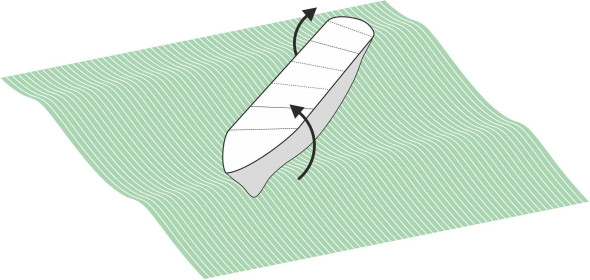
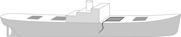
Somehow the engineer has to judge the effects of these loads on the different parts of the ship. Will each member be strong enough to handle the forces involved? The question is not so difficult if the member concerned can be pictured as if working in isolation. For example, the steel plates around the bow tend to distort inwards and outwards in heavy seas, a phenomenon called panting (figure 1). Panting produces only local damage and can be analysed independently of the ship as a whole [3]. Other members work together to handle loads on a much larger scale, and this is the topic we’ll turn to first. Only by considering the structure as a whole can we understand the role that each structural member plays together with the forces it must resist.
Figure 1
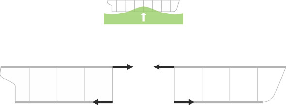
The ship as a girder
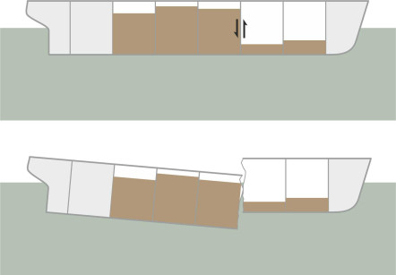
In structural terms, a ship is like a railway bridge. The difference is that most bridges span between two abutments without any support in between, whereas the weight of a ship is spread more-or-less evenly along the hull bottom. It sits on the water as if resting on an elastic foundation. The situation changes in rough water, but we’ll come to that in a moment – first let’s see what happens when the water surface is perfectly calm. This is only a preliminary exercise, but it’s an important one for a cargo ship because the cargo can weigh several times as much as the hull, and allowance has to be made for uneven loading between compartments. An empty compartment next to a fully loaded one can put the hull under severe stress in calm water even though the total load is well within the ship’s carrying capacity. It may even break the ship’s back, causing neighbouring compartments to shear apart as shown in figure 2. One can check whether this is likely to happen by dividing the ship into small sections and, assuming a particular pattern of cargo loading, calculating the forces acting on each section separately. These are the weight of the hull, the weight of the cargo, and the upthrust of the water. This leads to a ‘load diagram’ from which one can estimate the shear forces and bending moments at each section along together with the corresponding stresses in the plating and supporting frames [2] [6] [7].
Figure 2
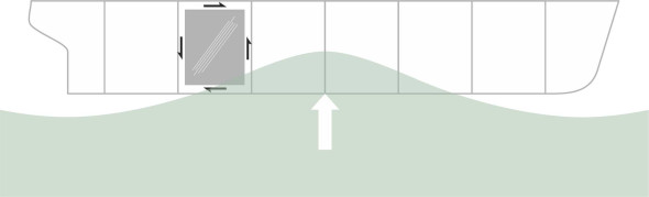
Wave action
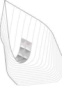
In a stormy sea the wave action brings in a new dimension, and the pressure on the hull is no longer uniform. When the waves grow beyond a certain height, the hull does indeed span between crests like a bridge, riding almost clear of the water surface in between the bow and stern (figure 3). It is commonly assumed that the waves move slowly, so they can be treated as if frozen in time - in other words, dynamic effects such as momentum, acceleration, and vibration can be ignored. A wave can take up any position along the ship, but there are two configurations likely to induce high stresses. They occur (a) when the hull ‘hogs’ over a single wave with the bow and stern unsupported, and (b) when it ‘sags’ between two waves with the centre unsupported. In either case it is possible to work out the hydrostatic pressure that each wave exerts on the hull assuming a trochoidal profile for the water surface, suitably adjusted using the Smith correction as set out in Section M1820. Treating the hull as a simple beam, one can then work out the stresses in the ship’s bottom, in the deck, in the hull plating, and in the reinforcing framework. One can also work out the deflections: when bridging between two waves, a medium-sized ship will sag by several centimetres in the middle relative to the bow and stern, while a larger ship will sag by half-a-metre [8].
Figure 3
This method of analysis overlooks several complications. It has been described as a ‘comparative approach’ for assessing a design against existing vessels of similar size and construction [7]. But it can’t handle the more complicated loading patterns that occur under wave impact such as racking forces in the transverse plane when the ship rolls (figure 4), or torsional loads over the cross-section if the waves approach at an angle as shown in figure 5. And nowadays the International Association of Classification Societies (IACS) requires the designer to take into account the statistical probability of failure [9]. Hence computer programs are routinely used to estimate the load pattern and to derive a statistical description of bending moments so that one can determine the likely range of variation together with the probability of extreme values exceeding the design limits. They incorporate wave spectra and use Response Amplitude Operators (RAOs) to account for the dynamic response of the ship. In addition, finite element packages can reveal the stress patterns that arise in different parts of the hull structure.
Figure 4
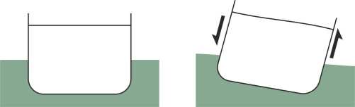
Figure 5
Stresses
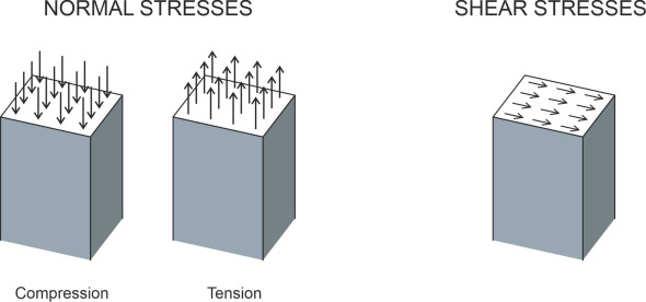
Whether or not the member is strong enough depends not so much on the load, but on the stress it engenders inside the material, the force per unit area of cross-section. To find its value at any given position we make an imaginary cut through the member concerned and work out what is happening in each small region of the exposed cross-section. Figure 6 shows the two fundamental two types of stress: (i) normal to the surface, and (ii) shear. Normal stresses can be tensile or compressive, the latter being represented as a ‘negative’ tension and written with a minus sign. If the member is carrying a ‘pure’ tensile or compressive load and nothing else, it is usual to make the cut at right-angles to the axis of the load and to assume the load is spread evenly across the exposed face. The stress is then equal to the load divided by the cross-sectional area. Bending loads are different: when you bend a plastic ruler you induce a combination of tensile, compressive and shear stresses in different parts of the cross-section. A torsional or twisting load produces shear stresses. We touched on some of these terms earlier in Section R1412, and you can find more details in one of the standard references [16]. Shortly we’ll look at the effects these stresses have on the material, and the different ways in which the material might fail.
Figure 6
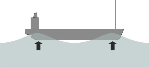
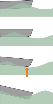
Slamming
If you watch a film of a ship in a storm, you’ll see the vessel rise over each crest and after a pause, crash into the next trough, with spray cascading over the deck in spectacular fashion. The sequence is shown diagrammatically in figure 7. In severe cases, a gap appears momentarily underneath the hull before it lands on the water. Under such an impact, the water behaves more like a solid than a liquid, and the result is a phenomenon called ‘slamming’.
Figure 7
What happens beneath the hull
The water behaves like a solid because (a) it’s not compressible and (b) it must accelerate out of the way. If the penetrating object has a flat bottom, the water has to move fast, and the sharper the impact, the higher the acceleration and therefore the greater the impact pressure between the water surface and the object. If you’re willing to carry a simple experiment, you can get a feel for the forces involved by slapping your hand onto the water in your kitchen sink as hard as you can. The surface feels much less forgiving than it normally does, more like mud than water. Now try it with a frying pan: the resistance is even greater.
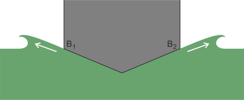
The situation is not very different from that of a planing vessel skimming across the water suface. It gets its support from ramming the fluid downwards at high speed: indeed, in Section M1718, we visualised planing as a two-dimensional phenomenon that could be simulated by dropping a wedge vertically onto the water surface. The same scenario applies to slamming. Back in 1929, the aerodynamicist Theodore von Kármán first conceived the wedge analogy while trying to estimate the impact of the water surface on a seaplane during landing. As shown in figure 8, he represented the hull as a 2-dimensional wedge that displaced fluid laterally to either side, ignoring any fore-and-aft component. By applying momentum considerations, von Kármán obtained a rough estimate of the slamming force as a function of the downward speed of impact \(V_R\) and the deadrise angle \(\beta\), and others subsequently improved on his results [1]. The angle \(\beta\) is critical. When it is small, the pressure near the perimeter of the contact area forces water out in a flurry of spray as shown in figure 9. The spray roots at the boundary are marked by the points B1 and B2.
Figure 8
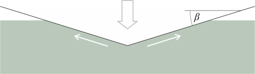
Figure 9
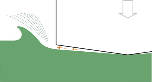
More recent research has shown that when \(\beta\) falls below \(3^{\circ}\), the speed at which water is ejected approaches the speed of sound in water: the expansion velocity of the wet surface is supersonic, and the shock wave makes the fluid behave almost like a solid material. This is what happens under the hull of a conventional ship with a flat bottom. In fact there is a further complication: the air itself resists expulsion from the gap and as the pressure rises it forms a temporary cushion. Naturally, the cushion distorts the water surface before the body enters (figure 10), and experiments at the Japanese Ship Research Institute have shown that around the periphery of the slammed area, the high-speed air jet mixes with water to form a fluid of intermediate density that chokes the air flow [1].
Figure 10
Impact damage
Slamming can damage the hull and make the whole ship vibrate. The instantaneous water pressure under the bow reaches several atmospheres and will momentarily deform the plating. Repeated deformation will eventually cause the metal to fail in the same way that a paperclip will break if you repeatedly bend it backwards and forwards – a phenomenon known as fatigue failure. Hence a merchant ship will usually travel under reduced power in rough conditions, typically when the wind speed reaches a strength of 6 or more on the Beaufort scale [13].
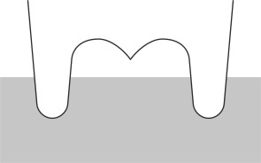
Faster boats also experience slamming, but for different reasons. When travelling at speed in rough water, planing vessels tend to bounce from one wave-crest to the next and the V-shaped profile under the bow is designed to penetrate the surface more gradually and thereby reduce the impact. Whether or not they plane across the surface, multi-hull vessels are vulnerable to wave impacts because of their shape, specifically the platform that spans between the side hulls. The underside is known as the ‘wet deck’, and it traps wave crests underneath. To lessen the impact, the wet deck of a wave-piercing catamaran has a V-shaped profile as shown in figure 11. It works in the same way as the deadrise of a planing vessel, by slicing into the water and deflecting it to either side.
Figure 11
Avoiding failure
To make the hull strong enough, the designer will tailor the thickness or diameter of each component so that the stress at its weakest point doesn’t rise above a certain limit. For the kind of steel used in a ship’s hull, the ‘allowable stress’ is fixed at a value typically between 100 and 175 N/mm2 [10] depending on the location of the material within the structure and the likely mode of failure. The same limit applies to both tensile (pulling) and compressive (squeezing) stresses. In either case, the stress is equivalent roughly to the weight of a bucket of water acting on each square millimetre of the cross-section.
Fundamentally, there are three ways in which a structure can fail. Either something breaks, or it goes out of shape, or it moves when it shouldn’t. Breakage can occur when tensile forces tear the material apart, while deformation typically arises from compressive forces that cause it to buckle. ‘Movement’ in the sense of vibration is a perennial problem with ships. We’ll consider tensile failures first, then briefly skim over the rest. For a more comprehensive coverage, you may like to consult [17], and in a marine context, [11] or [5].
Tensile failure
Tensile failure itself occurs in three different forms, each of which follows a distinct pattern according to the material involved. Ductile materials distort in a particular way before they break. For example copper is a ductile metal, and a copper wire won’t snap if you pull both ends, at least not straight away: it stretches because the sheets of molecules in each crystal slide over one another in preference to tearing apart. The process is called yielding, and once they begin to yield, many materials will continue to flow like molasses before they break. However, this is not necessarily a disadvantage. When struts and plates made from a ductile material are assembled into a complex structure, they behave in a more subtle way than they do on their own. If at any particular point the stress exceeds the yield stress, the metal will flow but as it does so, the loads will adjust their paths through the structure, transferring some of the burden to other parts with spare capacity in such a way that the stress concentration is relieved. The result is that the structure fails gradually by changing its shape before it breaks. It is safer than one made from a brittle material, which is liable to collapse or disintegrate without warning.
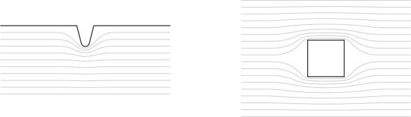
Steel is ductile too, and it’s the material from which most ship’s hulls are made. The ductility is essential, because, like many structures built on a large scale, a hull contains irregularities such as holes and surface notches. In the same way that the water in a stream speeds up as it flows around an obstacle, the paths that the loads follow inside the material squeeze together as they curve around any aperture or notch (figure 12), and the smaller the radius, the higher the stress. For example, a circular hole multiplies the value locally by a factor of three, and even higher values occur at the bottom of a scratch or notch where the radius is relatively small. However, ductile yielding comes to the rescue: the material yields and stretches in such a way that the radius of the notch increases. When the radius increases, the stress falls, and to some degree, the problem repairs itself.
Figure 12
Unfortunately, steel doesn’t always do this. Rather than yielding, under certain circumstances it becomes brittle and when the stress reaches a critical point, the material fractures at the base of the notch to form a crack that penetrates deeper into the structure. This has two effects. First, it reduces the amount of intact material that is left to carry the load, so the stress rises a little. Second, the stress becomes more concentrated at the tip of the crack where the effective radius is now microscopically small. The crack will therefore grow in length, and the rate of growth is very fast: around 500 mm/s. This has caused severe problems for merchant ships in past decades, for example, the Liberty ships that were built in large numbers between 1941 and 1945 in the USA. Engineers still talk about these remarkable vessels, which were designed to bring supplies to Europe across the cold waters of the north Atlantic during the Second World War. Not long after coming into service, some developed cracks which elongated to a length of a metre or more, often unnoticed, until the ship broke in two.
Crack propagation
At first, the cause was a mystery. The Liberty ships were among the first generation of all-welded ships to come into service, and some believed that the welding process was to blame. But the cause lay elsewhere. The person who solved the mystery was one of the first women to specialise in engineering research, Dr Constance Tipper [18], who showed that when subjected to low temperatures of the kind that convoys were experiencing in the North Atlantic at the time, the mild steel used in the plating of the Liberty ships was liable to turn brittle and crack at stress levels considerably less than those that it could normally handle.
Why hadn’t the problem arisen before? The reason was that prior to 1939, almost all vessels were riveted, and when a crack formed in a riveted plate, the stresses that caused it were unable to propagate across the edge of the plate into the neighbouring one. By contrast, the hull of a Liberty ship was effectively a continuous shell. The cracks began in places where the stresses were most concentrated, for example around the corners of the rectangular hatch openings in the deck as shown in figure 13, and they propagated right round the hull. As a temporary measure, if a crack was discovered at sea, it became common practice to drill a hole at each end, which reduced the severity of the stress concentrations and slowed down or prevented further propagation, and for new ships, the problem was resolved by rounding off and reinforcing the aperture corners. But it wasn’t until the late 1950s that awareness of the risks spread more widely within the shipping industry. Losses continued until the 1980s with the break-up of several ore-carriers, thought to be caused by local stress concentrations, cracking, and brittle fracture [15].
Figure 13
And cracks can occur in ductile materials as well as brittle ones. In parts of a ship’s hull, the stresses switch between tension and compression each time the vessel passes over a wave. A ship meets a lot of waves, resulting maybe in 10 000 stress reversals for each day spent at sea, and 30 million during the ship’s lifetime [9]. The reversals feed energy into the tip of each crack, lengthening it gradually until there is little sound material left to hold the structure together. After a large number of cycles the structure will break apart suddenly without warning, a phenomenon known as fatigue failure. It may appear similar to brittle fracture, but a fatigue failure takes longer, occurring only after an extended period of cyclical loading, and the crack itself has a different character when viewed under the microscope. Engineers have known about metal fatigue for many decades, but it first attracted public attention during the 1950s with the disappearance in flight of three de Havilland Comet jet airliners. More recently, it was implicated in the failure of railway tracks in the UK as detailed in Section R0414, and remains a problem with all kinds of vehicle in which the stresses oscillate over a wide range. But there are straightforward solutions. As with brittle fracture, the designer can strengthen a likely trouble spot or better still, change the geometry by rounding off re-entrant corners, after which the stress concentration will largely disappear. This is why all jet airliners today have oval windows rather than square ones even though square ones are easier to make.
Buckling and bending
To round off this topic we’ll turn briefly to two other types of structural failure: failure in compression and failure in bending. Let’s admit first that there is no such thing as a ‘compression failure’, at least not in the same sense as the tensile failure described above – there is no direct analogue. The reason is that when subject to an increasing compression load, a strut of the kind that you’ll find in a ship’s hull or an aircraft fuselage won’t squeeze like molasses into a shapeless lump: instead, it will buckle. The mathematics of buckling is beyond our scope here, but we can get an intuitive sense of what happens by picturing the behaviour of an everyday object under load. Here, the problem is not the strength or weakness of the material as such, but rather the geometry of the member. If you press together the ends of a plastic ruler with increasing force as shown in figure 14, it will resist until the load reaches a critical value, when the ruler suddenly bends into a ‘U’ shape. Like a vaulter’s pole, if the material is sufficiently resilient it will return to its original shape when you let go. A less springy material will snap in the middle or bend permanently out of shape.
A box is more complicated. Crudely, it folds like a concertina. A box will also buckle under other forms of load, for example torsion, and a sheet panel will buckle under a shear load. As an example of the latter, the steel plates along the side of a ship’s hull carry shear loads whenever the hull hogs or sags between waves as shown in figure 15. The plating is welded to steel members that form a supporting lattice. If the unsupported area is small, the plate will strongly resist shear, while a plate of the same thickness but unsupported over a larger area will wrinkle diagonally, effectively failing at a much lower level of stress. As a rule of thumb, a designer may reckon a square panel of side \(w\) to be vulnerable if its thickness is less than about \(w/70\) [8].
Figure 14
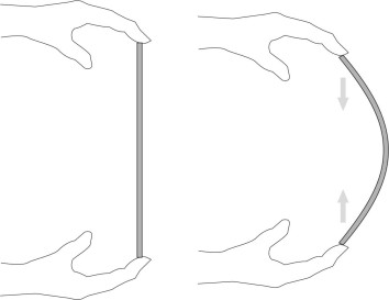
Figure 15
In some respects, bending is easier to understand. When you bend a toothbrush between your hands, the level of stress varies from top to bottom of the cross-section as shown in figure 16. Material along one edge is compressed while that on the other edge is pulled apart in tension. The same happens with a ship’s hull when it hogs over a wave crest: it is acting as a beam or girder, and the deck goes into tension and the hull bottom into compression (figure 17). For reasons we won’t go into here, the stresses vary among the components that make up the deck and similarly for the hull bottom. The contribution of each element in the deck structure must be calculated separately and the results combined to estimate the maximum tensile load that the deck can resist. Similarly for the compressive load in the hull bottom. Together, these two loads, one tensile and one compressive, determine the collapse bending moment – the point at which the entire hull fails. The stress pattern is reversed when the ship sags between two crests, but the same principles apply.
Figure 16
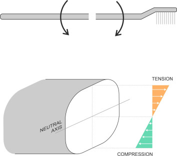
Figure 17
Vibration
Finally, we turn to the matter of vibration. Like any moving vehicle, a ship is an elastic structure that will oscillate like a vibrating string when excited. The frequency of vibration depends on the cause. The ship’s engines are the most prominent source of high frequencies, while the low frequencies arise from wave action. The latter can cause the hull to vibrate as a single body, a phenomenon sometimes called springing, and there are simple formulae from which one can estimate the natural frequency of oscillation [12]. A key question is whether the hull can resonate in time with the waves. For most ships, the natural frequency of longitudinal vibration of the hull in the vertical plane is too high - of the order of 1.5 Hz - but it falls with increasing length and for a large tanker it can be as low as 1 Hz, which makes resonance possible in a head sea. As described earlier, vibrations also arise from the hull slamming into the trough between successive wave crests, and the impact can leave the ship vibrating for as much as 30 seconds [14]. The vibrations occur at two distinct levels. The first is local: the plating between lateral and longitudinal supporting members vibrates like the skin of a drum. The second involves the entire hull: a longitudinal oscillation known as whipping that in practice is difficult to distinguish from ‘springing’. In the 1960s and early 70s, for some ships the frequency of large-scale whipping oscillations coincided with the resonant frequency of the hull acting as a girder. The result was a number of catastrophic failures, with bulkers and container ships breaking apart in mid-voyage [1].
If the worst happens
A ship is designed to survive in rough water. However, there are situations that the designer can’t reasonably allow for, like accidentally running aground for example, or hitting an obstruction. Hidden under the water surface are rocks and abandoned hulks that don’t always appear on charts, and not all commercial ships are equipped with the SONAR apparatus needed to detect them. Without SONAR, the master is blind to what lies in the vessel’s path, and over the centuries, many ships have been lost for this reason. A rock will pierce the plating, and a hole about 30 cm × 30 cm in size (one foot square) will admit 4500 litres (1200 gallons) of water per minute [4].
After hitting a rock, depending on the size of the rock and the state of the tide, a ship may float off, but be so badly holed that the rate of ingress of water is more than the vessel’s emergency pumps can handle (you may remember the headlines that accompanied the loss in 2012 of the Italian cruise ship the Costa Concordia, which was wrecked off the coast of Tuscany in this way. After a while it turned on its side, and 32 of the 4000 passengers and crew lost their lives). Alternatively, the ship may be pinned in place unable to move. It can no longer ride up and down with the swell, so the wave impacts become more severe. In the days of wooden sailing ships, the hull planking would work loose and scatter, and the structure would soon disintegrate into matchwood. A steel hull is more tenacious. Like the skin of a balloon it resists being completely pulled apart, and reinforced by lateral bulkheads and a double bottom (which are standard on modern vessels), it may delay inundation long enough for the passengers to be rescued even though the vehicle itself is damaged beyond repair.