M.0418
Answering the helm
If you want a job as a lorry driver, you have to pass a test. Among other things, a driver has to show that he or she can handle the vehicle safely using the throttle, brakes, gearbox, steering wheel, and ancillary controls. It’s not easy, but the process boils down to controlling two things: the speed of the vehicle, and its position on the road. The same can be said of a ship, but there are other factors that complicate the process. First, there is a time lag before the vehicle responds to each command, and second, a ship is not firmly located on a track, so it’s free to move in any direction under the action of the wind on the superstructure and the water below: the ship’s inertia together with external forces can carry the vessel off course. This may not matter in mid-ocean, but there’s less room for manoeuvre in other places, for example in a busy shipping lane, and especially when entering and leaving port. To steer through a harbour entrance and berth at the quayside calls for precise control, together with a vessel that responds to steering commands in a predictable way, turning quickly when necessary but otherwise holding a steady course. In the next Section (M0415) we shall be looking at specific manoeuvres, but here, we’ll prepare the ground by examining the dynamical processes involved. Most have to do with turning or changing speed, but one of them is different because it doesn’t involve the crew. Rather, it concerns stability: does the ship do anything it shouldn’t in the absence of any specific command? We’ll look at this issue separately from the others, and in a little more detail.
Manoeuvrability
After it is launched and fitted out, a new ship will undergo sea trials before being handed over to the purchaser. The trials include several manoeuvrability tests as prescribed by the International Maritime Organisation (IMO). The two most important ones are the turning circle test and the zig-zag test. Respectively, they determine (a) how quickly the vessel can turn, and (b) how quickly the vessel can stop turning in one direction and start turning in the other.
Turning circle test
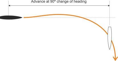
We’ve already met the concept of a turning circle in the previous Section. It is measured at several different speeds, each time starting with the ship travelling in a straight line. The helmsman shifts the rudder hard over to the starboard side (the maximum is usually \(35^{\circ}\)) and holds it there. The vessel will start to turn, slowly at first, but swinging round at an increasing rate so that it traces out a spiral whose curvature increases steadily until it converges on a circular path of radius \(R\) say. The test is then repeated with the helm to port, and the sequence repeated at a number of different speeds. The results indicate how the turning circle changes with speed, but in reality, ships rarely go round in circles, and the results yield two other measures that better reflect the manoeuvres carried out in normal service. The first is labelled advance: as shown in figure 1, it is the distance the ship continues to travel measured parallel to the original direction of motion after the turn commences [14]. It is measured at various stages of the turn, for example when the ship’s heading has changed through \(45^{\circ}\), and again at \(90^{\circ}\). We’ll denote the values of the advance at these two stages by x45 and x90 respectively. Both are useful measures of the ship’s ability to steer away from danger. For example, if there is a wall or a shoreline lying at right-angles across the ship’s path, then x90 represents the minimum clearance the ship will need to avoid crashing into it. Actually, it will need a little more, because as you’ll see from figure 1, the advance continues to increase after the heading angle has reached \(90^{\circ}\); also, x90 is measured relative to the ship’s centre of mass and takes no account of the finite width of the hull. For reference, the IMO stipulates that x90 should be no greater than \(4 \frac{1}{2}\) ship lengths [6].
Figure 1
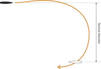
A second parameter can be derived from the turning circle test as follows. When the ship starts to turn, it deviates laterally from its original course, and the deviation, measured perpendicular to its original course, is called the transfer. It can be measured at one or more points along the ship’s path, typically when the heading has changed by \(90^\circ\) and \(180^\circ\); the latter is known as the tactical diameter (figure 2). It tells you roughly how much room the ship needs to turn around and face in the opposite direction. As you might expect, both the advance and the transfer rise as the ship’s speed increases; also, a single-screw vessel with a right-handed propeller will need less space when turning to port than it does when turning to starboard. The IMO regulations recommend that the tactical diameter for any given vessel should be no greater than 5 ship lengths. In fact, ships were doing pretty well in this regard over 100 years ago. The first passenger liner to establish a timetabled service across the Atlantic, the Mauretania, held the Blue Riband for 18 years after her maiden voyage in 1907. With engines full ahead and rudder hard over, her turning circle was said to be less than 4 lengths [18].
Figure 2
Zig-zag manoeuvre
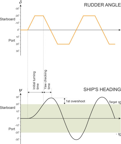
Once a ship has started to turn, because of its rotational inertia it will continue to yaw for some time after the helm is returned to midships. So an important feature of a ship’s behaviour is how quickly it stops turning. This is the rationale that underlies the zig-zag manoeuvre (otherwise known as the ‘Kempf manoeuvre’). Unlike the turning circle test, it measures the ship’s immediate response, and it involves relatively small changes in heading. The recommended procedure is set out in [8]. The test begins with the vessel travelling on a straight course at known speed \(V\). The helmsman lays the rudder over to starboard at an angle of \(20^\circ\), say (i.e., \(\delta = -20^\circ\) ), and holds it there while the ship turns until it reaches a ‘target’ heading \(\psi_e\) starboard of the original course. The target \(\psi_e\) will typically be \(10^\circ\) or \(20^\circ\). At this point the helmsman turns the wheel the opposite way until the rudder lies on the port side at an angle of \(20^\circ\) (\(\delta = +20^{\circ}\)) and holds it there. This takes several seconds. The ship won’t stop swinging straight away but rather continues to yaw and overshoots the target. Eventually the swing reverses and the ship yaws to port until it reaches a heading \(\psi_e\) to the port side of the original course. The manoeuvre is repeated for different rudder angles and ship speeds, and as shown in figure 3, when plotted on a graph the combined results give a picture of the ship’s ability to start turning and to pull out of a turn [14]. Three of the key performance measures are indicated in the lower part of figure 3. The first is the initial turning time. Each of the subsequent rudder reversals is characterised by two additional measures: the yaw checking time, and the overshoot angle, whose values may vary from cycle to cycle. Only the values for the first rudder reversal are shown in the Figure. The required performance standards are specified in the IMO regulations. They vary with speed, and they don’t apply to faster craft such as hydrofoils for example, which need to turn more quickly than a conventional ship.
Figure 3
Going astern
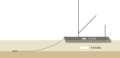
The turning circle test and the zig-zag manoeuvre are tools that enable us to compare vessels and check their performance against international standards. But the tests apply only to forward motion in deep water, and don’t necessarily tell us how a ship will behave in other circumstances. In shallow water, for example, a manoeuvre will usually take longer than it does in deep water, because as we’ll explain later, the narrow gap under the hull inhibits transverse motion. And when moving astern, a ship’s steering tends to be erratic or non-existent. As we saw previously in Section M0505, it relies on forward motion, or to be more precise, a steady flow of water directed aft over the rudder surface. This means that without assistance, a prolonged movement astern is difficult to manage regardless of the water depth. However, short movements are possible and sometimes essential for a large vessel to rotate on its vertical axis, for example at the end of a voyage. To make a \(180^\circ\) turn in a confined space, just like a car or a lorry the ship will turn short round, moving alternately back and forth in a manner we’ll describe later. And smaller boats can travel astern for an appreciable distance along a tidal river by drudging. In years gone by the technique was widely practised by sailing barges, enabling them to navigate up and down the narrow creeks around the estuary of the River Thames. It is still used today. As shown in figure 4, the current carries the vessel along stern first, with the anchor dragging along the waterbed so the current is moving slightly faster than the hull. The flow of water past the rudder in the ‘normal’ direction enables the helmsman to keep control [13].
Figure 4
Directional stability
It’s not difficult to make a ship change course: if you move the helm to port or starboard, it will start to turn. But once it has started, it may be difficult to stop. This used to happen with automobiles. As explained in Section C0418, during the last century, it was not uncommon for a car to ‘oversteer’, so that if the driver turned the steering wheel to the right, say, the car would yaw clockwise, and with the steering wheel held in a fixed position, the yaw rate would continue to increase so the driver would be obliged to turn the steering wheel back towards the central position to prevent the car from spinning out of control. Although the causal mechanism is different, a ship can behave in a similar way, and continue to yaw even after the rudder angle is returned to zero. Worse, when travelling on a straight course it can begin to turn of its own accord. Directional stability is about unwanted motion, and it’s this aspect of steering to which we now turn.
What is directional stability?
Imagine a ping-pong ball placed in a shallow bowl that you are holding in your hand. As shown in figure 5, the inner surface of the bowl is marked in the centre with a cross. The bowl represents a ship’s steering control: when you tilt the bowl, you are in effect providing steering input, i.e., changing the angle \(\delta\) of the rudder. The position of the ball represents the ship’s response, specifically the rate of yaw (which is usually measured in degrees per minute). When the ball rests on the cross, the ship is travelling in a straight line. If some external agency disturbs the system (for example, someone jogs your elbow) the ball will move away from the centre momentarily. But provided you return the bowl to a level position and hold it steady, the ball will find its way back to the cross without any help. Likewise, a ship that yaws momentarily when deflected by a wave or gust of wind will soon resume a straight course: it is directionally stable.
Figure 5
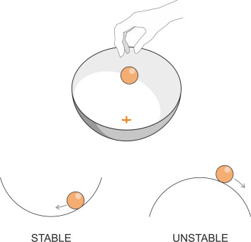
Now turn the bowl upside down and put the ball on top. The surface is smooth but it’s curved ‘the wrong way’, and you can’t balance the ball in the centre because the further it moves out of position, the steeper the downward slope and the faster it accelerates away from the centre. In effect, the shape of the bowl amplifies the intensity of any disturbance. What we have now is a vessel that is directionally unstable: when disturbed it will start to yaw and continue to do so at an increasing rate even though the rudder remains in its central position.
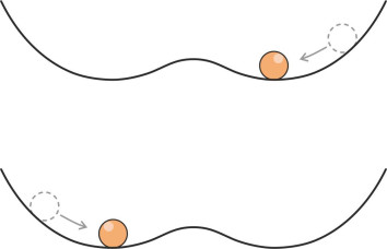
So what happens during a turn? Let’s go back to the original scenario, with the bowl the right way up. If you tilt the bowl by a pre-determined amount, the ball will roll to a new position off-centre and settle there. This is equivalent to swinging the rudder across and holding it at a fixed angle (say \(20^\circ\) to starboard), so the vessel yaws to starboard at a fixed number of degrees per minute. Now return the bowl to a level position: at this point you expect the ball to roll back to the centre. Likewise, when the rudder angle is restored to zero, if the ship is stable, the rate of yaw will decline until it resumes a straight course. If not, it will continue to turn indefinitely, but at a diminished rate [4] [15]. This corresponds to a bowl that has a hump in the middle – the ball stops short at point P in the depression on the near side of the hump as shown in figure 6. Had the manoeuvre started with the rudder laid over to port, the same would have occurred but with the geometry reversed: the ball would have stopped at point Q on the opposite side.
Figure 6
Such behaviour serves as a definition for instability in yaw, and it forms a basis of a recognised test for directional instability called the ‘Pull-out manoeuvre’ [15]. You lay the rudder to starboard at a predetermined angle and hold it there until the ship’s heading is changing at a steady rate. Then you return the rudder to its central position and observe whether the ship resumes a straight path. The procedure is then repeated with the rudder laid to port.
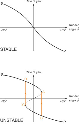
What the pull-out test doesn’t tell us is how the ship responds to less extreme steering movements that lie within the range corresponding to the hump at the bottom of the bowl in figure 6. How do we, metaphorically speaking, get the ball from P to Q? One way to find out is plot the relationship between rudder angle (input) and yaw rate (output) on a graph as shown in figure 7. This forms the basis of a second test for directional stability known as the Spiral or Dieudonné Manoeuvre. One might begin with the rudder angle \(\delta\) at \(-35^\circ\) (i.e., hard a-starboard) so the ship is yawing to starboard at a steady (positive) rate. Then gradually we swing the rudder over to the opposite side, observing how the yaw rate changes during the process. The upper part of figure 7 shows what happens with a stable ship: the curve falls smoothly from top left at S to bottom right at P, so that each small change in rudder angle nudges the yaw rate gradually in the direction you’d expect. But for an unstable ship, as shown in the lower part of figure 7 the curve displays a ‘hysteresis loop’ [4] [10] so that within the central region, the slope appears to reverse as shown by the dashed line. We don’t observe intermediate points along this part of the curve because the system is unstable and cannot progress in continuous fashion between neighbouring states, any more than the ping-pong ball can rest on the hump between P and Q. What actually happens is that after starting at S, the rate of yaw declines as you would expect, but doesn’t fall to zero when the rudder passes the neutral position. It will continue to yaw to port until the system reaches point A, where it ‘jumps’ discontinuously to point B and the direction of yaw is reversed. Similarly, if you start with the rudder laid over to port (point P) and move it gradually towards the neutral position, the ship continues to yaw to port until the system reaches point C, where it jumps to point D and promptly switches direction. All sustainable states lie on the heavy black curves, and since neither crosses the \(\delta\) axis, the ship can’t maintain a zero yaw rate and therefore the helmsman can’t hold a straight course: the only option is to switch between a starboard yaw and a port yaw at regular intervals. Systems that behave in this way have been studied extensively within a branch of mathematics called ‘catastrophe theory’ (see, for example, [19]).
Figure 7
This kind of instability has caused problems in the past. During the 1960s, there was a notorious case involving a Channel ferry called the Falaise, which without warning, tended to veer to one side or the other while manoeuvring in harbour and as a result, it damaged the pier at Newhaven on the south coast of Britain. On a later voyage, it damaged the pier again, this time under a different master. Both masters were unjustly penalised. We’ll see how the problem was cured later.
When ships go sideways
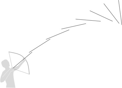
There is a simple explanation for the erratic behaviour of the Falaise. During the 1950s, the kids who lived in my neighbourhood made bows and arrows out of bamboo and string. The arrows would fly about 20 m into the air, but disappointingly, they slewed off-course (figure 8). The resulting drag slowed them down and greatly reduced their range, which in retrospect was probably a good thing. The reason is that without fletches or stabilising fins, an arrow is just an elongated cylinder. An elongated body of uniform cross-section has a preferred orientation when moving through a fluid, and it’s not what you might think: instead of pointing straight ahead, it turns at right-angles to the oncoming flow. Why? Any slight disturbance will change the cylinder’s orientation: by definition, the body assumes a non-zero angle of attack. For reasons explained in Section F1816, it will then experience a hydrodynamic couple that rotates the body further. This raises the angle of attack so the disturbing couple increases. The angle and the couple reinforce one another progressively until the body finishes broadside on to the flow [9] [11]. If it’s not correctly designed, a ship will behave in the same way. When it moves forward under power, a slight disturbance in the water along the side of the hull may trigger an unstable response: the ship swings round either to port or to starboard and continues to do so until the master brings it under control with the rudder. Independently, aerodynamic pressure acting on the superstructure can also to make the ship yaw. If the engines are shut down and the ship is allowed to drift without power, it will rotate until the wind is on the beam [1] – not a pleasant prospect in a rough sea. The underlying mechanism is the same in each case. It is known as the Munk moment and you’ll find a more detailed explanation in Section F1816.
Figure 8
Assessing stability
Stability is an elusive notion. If a hull is directionally unstable, you can see from its behaviour that something is wrong, but measuring the instability and diagnosing the cause is a different matter [2]. Yaw stability is sensitive to small changes in the forces that the water exerts on a moving hull, and it can’t reliably be predicted from hydrodynamic theory or model tests. Apart from simulation, this leaves the designer with little choice but to build the vessel and test it to see what happens. We have already mentioned two tests as indicators of unstable behaviour: the Pull-out test, and the Dieudonné test; in addition, the Zig-zag manoeuvre, although primarily a test of manoeuvrability, can provide useful information [4] [6] [14].
But we do know that stability is influenced by the proportions of the hull - in fact, they influence a ship’s manoeuvrability as well. This is not surprising if we regard stability and manoeuvrability as opposite sides of the same coin: a vehicle that performs well in one respect tends to perform less well in the other. For example, other things being equal, a longer ship will turn less quickly and be less manoeuvrable than a shorter one, while being more stable in yaw. Similarly, if two vessels of equal displacement have different drafts, you would expect the one with the deeper draft to be less manoeuvrable than the other, but more stable in yaw - although not all authorities agree on this [15].
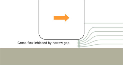
Another factor that affects both manoeuvrability and stability is the water depth [12], because in shallow water, there is less room for the fluid to move laterally underneath the hull. Suppose the vessel is turning to starboard. The stern must swing sideways to port, pushing fluid out of the way. Some of the fluid will take the easiest route, escaping underneath the keel. But as shown in figure 9, a narrow gap between the keel and the seabed will obstruct the cross-flow and inhibit the yawing action: in most cases the ship will be (a) more stable, and (b) harder to manoeuvre, and because it takes longer to turn through any given angle, its turning circle will increase in size [3].
Figure 9
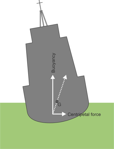
A third factor that we haven’t mentioned so far is the vessel’s speed. It affects stability in two ways. First, a vessel switches from stable to unstable behaviour when its Froude number exceeds a certain level, and although we won’t go into detail here, this behaviour seems to be related to the wave pattern that it generates when moving at high speed [7]. Second, the centripetal force that a ship needs to maintain a curved path derives from the difference in water pressure acting on either side of the hull below the waterline. Figure 10 shows a vessel turning to starboard, viewed in cross-section from astern. The arrows represent the forces applied to the hull surface by the surrounding water. The centripetal force creates an overturning moment around the centre of mass, which is usually above the waterline. Just like a car or a lorry, the vessel will heel outwards, potentially at a dangerous angle [4] [14]. By contrast, planing craft tend to heel inwards because of their V-shaped hull cross-section, whose interaction with the fluid cross-flow underneath leads to a different pressure distribution on the hull surface [5].
Figure 10
Stabilising measures
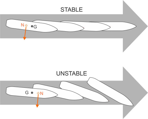
A necessary condition for directional stability – though not a sufficient one - is that the neutral point N (the lateral centre of pressure) lies aft of the centre of mass G [11] (you’ll find an explanation of the neutral point in Section F1816). Then as shown in figure 11, if the hull yaws momentarily owing to a disturbance of some kind, the Munk moment will not exacerbate the deflection. If the body is completely immersed in the fluid like a submarine or an arrow, one can tackle the problem in either of two ways. The first is to locate G towards the front. As the eminent hydrodynamicist G F Newman put it: ‘…the position of the centre of gravity is of great significance for the dynamic stability of ships, and indeed for other vehicles as well’ [11].
Figure 11
But this doesn’t work for an existing ship, because moving the weight forward will upset the trim – the stern will rise in the water and neutral point N will move forward too. For an existing ship, the best solution is to move N aft. In the same way that you add feathers to the tail of an arrow, you add more area to the aft portion of the ship’s hull when viewed from the side. An extended keel will help, alternatively a fixed fin or skeg just ahead of the rudder. The owners of the Falaise cured its endemic instability by filling in some of the empty space between the hull and the propeller with steel plate [16] [17]. An alternative would have been to increase the area of the rudder itself. When held in its central position, the rudder contributes to stability, and in this sense, it is one of the few measures that can improve both stability and manoeuvrability at the same time.
Where next?
A ship can be awkward to handle in a confined space, and the bigger the vessel, the greater the risk if anything goes wrong. But ships are subject to unpredictable forces; their steering systems lose some of their effectiveness at low speeds, and don’t always provide the degree of control one might like. From time to time, somewhere in the world a ship with a small margin of stability will collide with a harbour wall, causing damage that is costly to repair. On the other hand, a ship that resists turning movements may be just as difficult to handle as one that turns easily. In a busy seaway, a ship may need to change course quickly to avoid a collision, and the faster the vessel, the greater the manoeuvrability required, because the master has less time to respond to events as they unfold in the ship’s path. Hence a supertanker can benefit from a limited degree of instability provided the steering is controlled by autopilot [11]. The next Section will focus on particular manoeuvres that ships are expected to undertake, including changing course, emergency manoeuvres, and docking.