© Walter Baxter
F.1818
Vortices
‘Whirling and swirling vortices in water and air...are the sinews and muscles of fluid motion’
Last summer, I was walking along a country lane when something caught my attention. A bunch of leaves danced across the road. They swirled around, rising in a column then falling to the ground. After a few seconds, they rose and fell again. Along the road ahead as far as I could see, nothing else was moving. I stopped to watch. A breeze stirred in the valley to the left, but did not seem to penetrate the trees that lined the roadside. How could it focus so much energy on such a small area? It was clearly a vortex arcing down onto the road surface. Although only a metre or so in diameter, the high velocity at its core had stirred the leaves into motion and raised them an appreciable distance above the road. This behaviour was intriguing. When a solid object revolves, its outer surface moves quickly while particles near the axis, although rotating, scarcely move at all. Mysteriously, the fluid in a free vortex does the opposite: the particles near the centre move faster, and closer they are to the central axis, the higher the velocity and the lower the pressure. You can see this see more clearly in a liquid than a gas. Just watch the oars of a rowing boat. As it dips into the water, each blade will make an eddy on the surface just a few centimetres across, the outward sign of a spinning column of fluid below. Towards the centre, the fluid forms a dimple on the surface where it is moving faster than the blade. How this can happen, and where the energy comes from, are questions that we’ll try to answer in this Section.
Vortices in nature
Vortices occur naturally in different shapes and sizes. The largest that we see on earth are the weather systems in our atmosphere, hurricanes in the Atlantic and typhoons in the Pacific that begin their lives at sea. Each takes the form of a revolving disk that measures hundreds of kilometres across. A tornado isn’t quite so large but its whirling motion is powerful enough to cause devastation on the ground. At the opposite end of the scale are local disturbances that occur in the lee of trees and buildings, picking up leaves and sometimes dropping them on your doorstep.
Figure 1
Weather systems
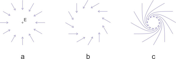
The air currents inside a hurricane or typhoon are quite complicated, but the process is driven essentially by a ‘pump’ that sucks out fluid and removes it from the flow field. At the centre of the storm is a damp column of air which expands and rises when heated by the sun. It’s a self-sustaining process because the vapour in the column condenses and releases latent heat which itself warms the column, and as the air ascends more rapidly into the stratosphere, it draws in cooler air from the surrounding region below. We shall picture the flow field as a two-dimensional disc at surface level, noting that there is effectively an exit at the centre; it is marked with the letter ‘E’ in figure 1a. If there were no circulation, the particles would be drawn radially in straight lines towards E, and it’s not difficult to see that they must speed up as they do so. If we divide the flow field into concentric rings centred on E, the rate at which particles cross any ring must be the same as the rate at which they cross any other ring. Since the circumference of each ring is proportional to its radius r, then provided the fluid is incompressible and the disc is of roughly uniform thickness, the radial velocity of the particles must be inversely proportional to r, increasing rapidly as they approach the centre. This doesn’t explain the circulation, but if tangential motion does occur the pumping action will reinforce it, stabilising the system around the rising core so that it can persist for many weeks.
However, there is in fact a second mechanism that causes the fluid to circulate around E at the same time. In a storm system, the circulation is triggered by the Coriolis effect. As explained in the Appendix, within the northern hemisphere, the inertia of any fluid particle that happens to be moving across the earth’s surface causes it to veer to the right (figure 1b). Consequently, instead of heading straight for the centre, the particles turn to the right and spiral towards the centre of the storm in an anticlockwise direction as shown in figure 1c. In the southern hemisphere, the spiral is clockwise. As with an ideal fluid, once they are drawn into a curved path the particles on the inside of a curve speed up relative to the ones on the outside. In fact we derived an equation in Section F1919 (equation 31) showing that for an irrotational fluid moving along a circular path the velocity along each streamline is inversely proportional to its radius. So we expect the air particles in our storm system to move with both a radial velocity component and a tangential velocity component, both of which increase in proportion to 1/r as the radius decreases. Close to the storm centre, they are moving very fast.
There are many other kinds of vortex that occur naturally in the earth’s environment: a useful summary appears in [2]. The direction of rotation depends on whether any external influences such as the Coriolis force are at work. In the northern hemisphere, tornadoes revolve more often than not anti-clockwise, while in the southern hemisphere, they revolve in the opposite direction. The smaller systems have no central ‘pump’, so like the vortex that rearranges the leaves in your back yard, they don’t last very long.
In your kitchen sink
You can make a vortex at home that simulates the effect of a hurricane. It has a clearly-defined structure and will persist long enough for you to see what is going on. Fill your kitchen sink with water and wait until the water is perfectly still. Then remove the plug: the fall in pressure will cause a dimple to appear on the water surface. If there are any grains of dirt on the surface, they will circle around it. But they don’t move like the spokes of a wheel: those near the centre travel faster as they spiral in towards the dimple, while those further away lag behind. Soon, a hole will appear that extends downwards to the plughole. Over the next minute or so it will grow in size until the water disappears with a satisfactory gurgle.
Like a rotating weather system, the water in your kitchen sink has a built-in ‘exit’. When you remove the plug from the sink, the water drains away under gravity. But the Coriolis force is too small to have any effect – it is swamped by other factors, so the direction of flow in your bath or basin can be either clockwise or anticlockwise depending on whether there is bias in the shape of the receptacle, or a random fluctuation in the motion of the water before it starts to drain.
Figure 2
Mathematical models
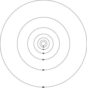
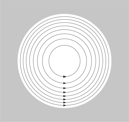
Many of the great nineteenth-century physicists such as Helmholtz and Kelvin were fascinated by fluid motion, which they tried to explain in terms of mathematical models. The equations for viscous flow were too difficult to solve, so they pictured a fluid as slippery substance with zero viscosity that you couldn’t grab hold and make it spin – the flow was irrotational. The models nevertheless led to useful predictions about certain fluid phenomena, among them the free vortex whose circulating flow field is shown in figure 2.
Figure 3
The free vortex
A ‘free vortex’ is an idealised pattern of flow in which particles of non-viscous fluid circulate around a central axis. Individually the particles don’t rotate so if you imagine each one as having an identifiable head and tail, the head always points in the same direction no matter what is happening anywhere else in the flow field. Since there is no central pump to remove fluid from the core, instead of spiralling towards the centre, each particle follows a circular orbit. We’ve already mentioned that under these conditions the particle velocity \(U\) varies from one orbit to the next, being inversely proportional to the radius \(r\), so that
(1)
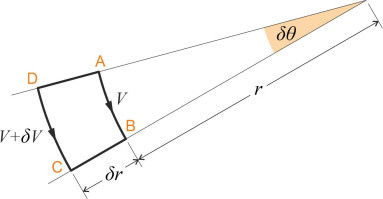
\[\begin{equation} U \quad = \quad \frac{k}{r} \end{equation}\]where \(k\) is a constant. It’s quite easy to check that this flow pattern is irrotational, by drawing a small element as shown in figure 3, and working out the circulation \(\delta \Gamma\) for that element. For the side AB, whose length is \(r \delta \theta\), we have a tangential velocity component \(- k / r\) (negative because it tends to rotate the element clockwise). For side BC the tangential velocity component is zero, and the same applies to side DA, so neither contributes to the circulation. Finally, for side CD, whose length is \(( r + \delta r ) \delta \theta\), the tangential velocity component is \(k / (r + \delta r)\) anticlockwise. Summing the increments of velocity times length around all four sides, we get
(2)
\[\begin{equation} \delta \Gamma \quad = \quad \left( -\frac{k}{r} \right) r \delta \theta + \left( \frac{k}{r+\delta r} \right) \left( r + \delta r \right) \delta \theta \quad = \quad 0 \end{equation}\]The right-hand side comes to zero, and since by definition \(\delta \Gamma\) is the differential circulation per unit area, the vorticity is zero too. This is true for any element within the flow field provided it doesn’t enclose the singularity at \(r = 0\), where the vorticity is infinite. Moreover, Bernoulli’s Law tells us that since the velocity increases towards the centre, the pressure must fall. From equation 24 in Section F1918 we have
(3)
\[\begin{equation} p + \frac{1}{2} \rho U^2 + \rho gz \quad = \quad \text{constant} \end{equation}\]If we denote the constant on the right-hand side by \(C\), omit the hydrostatic pressure term, and substitute the right-hand side of equation 1 for \(U\), then equation 3 becomes
(4)
\[\begin{equation} p \quad = \quad C - \frac{\rho k^2}{2r^2} \end{equation}\]which tells us how the pressure falls with decreasing radius.
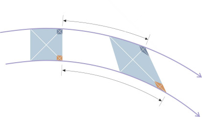
Equations equation 1 and equation 4 are crucial. They set out the defining features of a free vortex, which are that close to the centre, (a) the pressure falls, and (b) the velocity increases without limit. Such behaviour is counter-intuitive, and it’s worth pausing for a moment to imagine how it might come about. Since a free vortex is irrotational, the individual particles have zero angular velocity, each continuing to face the same compass direction as it orbits the centre. This applies not only to vortices, but in fact is a defining characteristic of any ‘potential flow’, i.e., a flow pattern involving an ideal fluid in steady motion. It arises because the particles in an inviscid fluid can only interact in one way. They can squeeze each other so their shapes become elongated, but since none can exert or respond to a ‘grip’ – a tangential force - they can’t be persuaded to rotate. Imagine a chunk of fluid on a circular orbit; in figure 4 it appears coloured in blue. At the beginning the outline is more-or-less rectangular, but as the fluid chunk moves round the curve, it deforms into a diamond shape so that the legs of the diagonal cross remain at an angle of \(45^{\circ}\) to the horizontal axis. If they didn’t, we would know the fluid was rotating. Now consider the two smaller particles indicated by the dark blue rectangle in the top right-hand corner and the red one in the bottom right-hand corner. The red one travels further, indicating that the particles on the inside of the curve travel faster than those on the outside. You can think of the fluid as propelled forward like the paste coming out of a toothpaste tube, squeezed between the streamlines on either side.
Figure 4
The forced vortex
A forced vortex is very different. In its simplest form, it is just a revolving body of fluid in which the individual particles appear locked together as a solid mass. One can create a forced vortex in the laboratory by putting fluid in a container and then spinning the container on a turntable. The friction of the walls cause the fluid inside to revolve although it may take some time to reach the same angular velocity as the turntable.
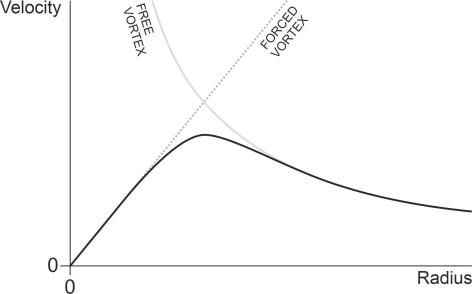
Unlike the particles in a free vortex, those near the centre of a forced vortex move quite slowly; in fact the speed is zero at the centre and it increases linearly with radius \(r\) just like it would in a rigid object such as a bicycle wheel. This is reflected in the way the streamlines crowd together round the outside as shown in figure 5. The velocity profile in turn affects the pressure distribution. It can be shown that because of the centrifugal force, the pressure rises in proportion to \(r^2\) so it increases rapidly towards the outer regions of the rotating mass [1]: when embedded in a larger flow field, a forced vortex must be constrained by the pressure of the surrounding fluid so it doesn’t fly apart. In the turntable experiment, the constraint is provided by the container walls.
Figure 5
Vortices and moving vehicles
Free vortices often occur in nature on a relatively small scale, such as eddies in a river or in the wake of an aircraft wing. Equation 1 describes their internal motion fairly well, except in the core where the velocity can’t actually be infinite. But it doesn’t explain how such a vortex might be created if there are no external forces to trigger the circulation. Neither eddies in a river nor vortices trailing from an aircraft wing have a pump at the centre to reduce the core pressure, and neither is affected by the Coriolis force.
Formation
In fact the distinguished German scientist Hermann von Helmholtz (1821-1894) showed that if the fluid is inviscid and the flow field irrotational, no matter how tortuous its path, the fluid cannot develop a vortex, and conversely, if a vortex did develop, it could never be destroyed. A century ago, this posed a difficult problem: vortices were essential for understanding the fluid resistance generated by automobiles, trains and marine craft, together with the lift generated by an aircraft wing. Was there a mechanism through which they could develop spontaneously within the vehicle wake?
Figure 6
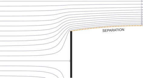
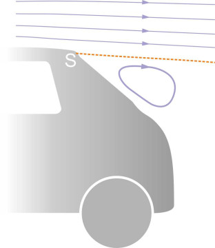
To make a fluid mass revolve, common sense suggests that some external agency is needed, something that grips the fluid and spins it around in the same way that you might grip a pencil and roll it between the palms of your hands. The obvious candidate is viscous friction, which enables chunks of fluid to transmit shear forces among themselves, so that a fast-moving layer sliding across the top of a slow-moving region of fluid can make the latter revolve. Over the years, experiments have shown that shear discontinuities of this kind occur in the wake of a moving body where the flow breaks away or separates from the body surface as shown in figure 6. The point of separation often occurs at a sharp corner, or at a point close to the rear of a bluff body such as the trailing edge of a passenger car roof, marked by the letter ‘S’ in figure 7. Like a sheet of sandpaper, the separated layer shears across the fluid beneath along the dashed line, and given a sufficiently low Reynolds number, the fluid beneath will revolve as a coherent body of fluid. The revolving mass is called a bubble vortex or separation bubble. The particles inside don’t necessarily move in the same way as the particles in a free vortex. Their velocity profile may be intermediate between that of a free vortex and that of a forced vortex.
Figure 7
At higher Reynolds numbers there is more energy in the flow field and the bubble structure breaks down into smaller disturbances that spread throughout the wake of a fast-moving vehicle. They are a distinguishing feature of turbulent flow. Fleeting and irregular in shape, they transfer energy from the vehicle to the fluid, in other words they contribute to the ‘drag’ that slows the vehicle down.
Figure 8
The viscous core
Forced vortex flow doesn’t arise very often in nature, at least not in its entirety. In most cases, the velocity profile of a revolving body of fluid is closer to that of a free vortex, because fluids of modest viscosity have a tendency to behave as if they were inviscid over much of the flow field. But this doesn’t apply within the core. Earlier we saw that the free vortex model predicts a mathematical ‘singularity’ where the velocity approaches infinity at the axis. Real fluids can’t do this because the implied shearing motions are inhibited by frictional resistance. Measurements on vortices created in the laboratory have confirmed that in this area, viscous forces dominate and the particles revolve at finite velocity as a solid mass: in effect there is a forced vortex embedded within the core. There are two ways to represent such behaviour. One is to model the two components separately, with the velocity profiles adjusted so there is a smooth transition at the interface. The second way is solve the Navier-Stokes equations for a viscous fluid across the whole of the flow field, with suitable constraints. Historically, the solution is called the Lamb-Oseen vortex, whose velocity profile is sketched in figure 8. You can see that in the outer region, the curve resembles the velocity profile of a free vortex, while closer to the axis, it resembles that of a forced vortex in which the velocity falls to zero at the centre. Further details can be found in [8].
Figure 9
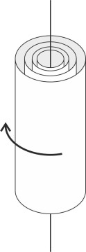
Vortices in three-dimensional space
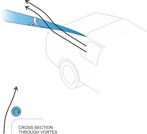
So far we have concentrated on what happens inside a vortex at a typical cross-section. Now it’s time to look at the three-dimensional whole. A vortex is not just a flat disk, but more like a cylinder that extends above and below the plane of the cross-section as shown in figure 9, so that the particles revolve around a line along the central axis as opposed to a single point. Analysts call the axis a vortex filament. In a tornado or in your kitchen sink, the filament is roughly vertical, but in the case of a moving vehicle this is not usually the case. Here, each vortex springs from a line of separation that we can imagine painted on the body surface. As described in Section C1416, aft of the rear window of a hatchback there is often a line of separation situated horizontally at right-angles to the direction of motion. Provided the vehicle isn’t moving very fast, it generates a bubble vortex that is carried along in the vehicle’s wake as shown in figure 10; in fact two such vortices are shown, rotating in opposite directions. If, on the other hand, the line of separation is not normal to the direction of vehicle motion but inclined at some other angle as shown in figure 11, a bubble forms underneath as before, but the vehicle leaves the rotating mass stretched out behind in the form of a trailing vortex in which the particles now follow a corkscrew path [5] [7]. Sometimes the line of separation is almost parallel to the direction of fluid flow, as happens underneath a ship’s hull either when moving straight ahead as described in Section M1619, or during a turn as described in Section M0505.
Figure 10
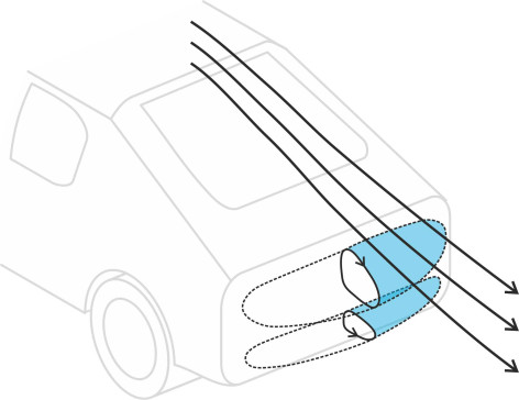
Figure 11
You might wonder what happens at the end of a vortex filament: if it’s a bubble, does it have a fixed length beyond which the rotation abruptly ceases? The answer is no, nor can a trailing vortex stretch out indefinitely. In theory, one of two things must happen: (a) each end terminates in a solid boundary such as a vehicle body or the earth’s surface, or (b) both curl round and join up to make a closed loop known as a vortex ring. A tornado is an example of a vortex whose lower end terminates at a solid boundary, in this case the earth. The interface on the ground is interesting because it’s the only part of the environment that is exposed to the low pressure in the vortex core, and this in turns explains why a tornado is so destructive – it doesn’t just blow things around, but sucks them into the air at the same time. This is why, if you visit your local park on a windy autumn day, you’ll see pockets of leaves rising into the air as if caught up in a mysterious dance.
Figure 12
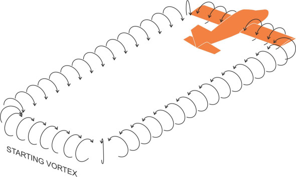
By comparison, vortex rings are less common. In past centuries, smokers would amuse children (and each other) by blowing smoke rings across the room. In still air, they were sufficiently stable to last for several seconds. On a larger scale, the vortex ring is an integral part of the process that generates ‘lift’ to support an aircraft in flight. You’re probably aware that an aircraft creates a trailing vortex at each wingtip. The two vortices actually form part of a continuous loop. At the front they merge with the air circulating around the wing cross-section, while at the rear they are connected to something called the starting vortex that comes into being and rolls along behind of the wing when the aircraft starts to move along the ground before taking off. Once the aircraft is aloft, the loop stretches out and the starting vortex is left behind (figure 12). It soon dissipates owing to viscous friction.
Conclusion
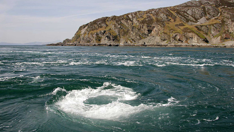
In everyday life, people imagine a vortex as an exotic and dangerous phenomenon that draws in anyone who passes nearby. The idea is possibly rooted in Greek mythology, which tells of a monstrous being Charybdis who created a whirlpool in the Straits of Messina that could devour a whole ship. One of the world’s strongest whirlpools that we know of today is the Corryvreckan off the coast of the Scottish Island of Jura [3]; like others of its kind it arises from tidal currents close to the shoreline. Other kinds of vortex are hazardous too. We’ve already mentioned tornados and tropical storms, but in this web site we are particularly concerned with the ones created by moving vehicles: for example, the vortices trailing from the wings of a passenger jet, which can de-stabilise other aircraft following close behind. In all these cases the principal risk is the high fluid velocity near the core. Less spectacular are the vortices that permeate regions of disorderly fluid motion where they do relatively little harm, for example in the wake of a road vehicle, or downstream from trees and buildings in the city centre. On a smaller scale, they are the building blocks of motion in a turbulent flow field: random, fleeting disturbances that are difficult to observe even in the laboratory and that so far, have not yielded to mathematical analysis. How they fit together in 3D space and how they dissipate energy remain among the most challenging problems in the mechanical sciences today.
Appendix: The Coriolis effect
To understand the Coriolis effect at an intuitive level, imagine you are standing at the centre O of a playground roundabout that is rotating anti-clockwise at a steady angular velocity \(\omega\). You take a ball out of your pocket and roll it outwards towards the edge of the platform. It leaves your hand moving radially at velocity \(v\) (left-hand diagram in figure 13). You expect the ball to roll away from you at constant velocity in a straight line along the platform surface. But this is not what actually happens: the ball veers to the right as shown in the Figure. This deviation is a manifestation of the Coriolis effect: the ball travels in a straight line relative to the earth, but as it does so, the platform on which it is rolling both turns on its axis and moves across its path with increasing velocity – hence the path of the ball curves relative to the roundabout platform.
Figure 13
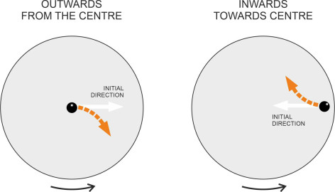
A similar effect occurs if you roll the ball in the opposite direction. Imagine you are standing close to the edge of the roundabout at a radial distance \(R_0\) from the centre. Now roll the ball inward towards the centre as shown on the right-hand side of figure 13. Before you let it go, the ball is travelling with you around the platform circumference. When it leaves your hand, its velocity has two components: a radial component \(v\) and a circumferential component \(\omega R_0\) to your right (assuming you are facing inwards). As the ball travels towards the centre of the roundabout, the radius of its trajectory decreases, the platform turns and the circumferential velocity of the platform beneath falls, so the ball’s inertia causes its path to veer away from the radial direction, again to the right. It’s not difficult to analyse and predict the geometrical path that the ball follows relative to the platform, but the dynamics are more subtle and more complicated than pictured in this brief introduction: in fact the ball undergoes two distinct types of acceleration, and to tease them apart is an interesting mathematical challenge. For now, we’ll just summarise what is going on as follows: the Coriolis effect changes the path of a freely moving body as viewed within a rotating frame of reference, accelerating the body at right-angles to its existing trajectory. If the rotation is anti-clockwise, the body veers to the right, but if it is clockwise, the body veers to the left. It can be shown that the acceleration has magnitude \(2 v \omega\), and this value applies not just to a body moving radially inwards or outwards, but also to a body moving circumferentially or indeed in any direction relative to the rotating frame of reference [4] [9].
The Coriolis effect influences all kinds of motion, not just mechanical devices such as a rolling ball. In fact the earth itself is a rotating platform, and while the angular rotation is slow compared with a playground roundabout, the tangential velocity at the equator is quite high: a little over 450 meters per second, around 1,000 miles per hour. So any body moving at moderate speed across the earth’s surface is subject to the Coriolis effect: the acceleration can affect a large fluid mass, for example, the earth’s atmosphere, or an ocean. On a global scale, these bodies revolve with the earth’s surface, turning anti-clockwise in the northern hemisphere and clockwise in the southern hemisphere. As you might expect, a local disturbance caused by a pressure gradient will move fluid particles away from a high-pressure region towards one of lower pressure, but during transit their path is deflected to the right relative to the earth’s surface. In the southern hemisphere, the direction is reversed and the path of a moving fluid will be deflected to the left.
Acknowledgement
Picture on leading page: The Corryvreckan whirlpool, Photographer Walter Baxter, CC BY-SA 2.0, https://commons.wikimedia.org/w/index.php?curid=33579199 (accessed 22 September 2019).