R.0118
Driving a train
When driving a car – especially when cornering at speed – you can sense the bumps in the road and the strain in the tyres though the steering system, which is connected to the front wheels. Driving a train is different because there is no steering wheel, and no direct connection between the controls and the surface the train is standing on. However, there is still much for the driver to think about. Apart from anything else, a train is not a single vehicle but rather a collection of vehicles that push and pull one another with considerable force. The impact can build up as it passes along the train, which is why passengers in the last coach of a steam train often used to feel an abrupt jerk when the train started off. Even today, in the case of a freight train it is possible for a longitudinal impact that travels like a wave along the formation to break a coupling or bounce a wagon off the rails. So a train driver needs to picture the forces involved and to think ahead. One must stay alert for long periods, keep an eye on the instruments in the cab and the look out for signals in what is often a monotonous or confusing visual environment. Nevertheless, thousands of young people still want to become train drivers: it is one of the most popular career choices in the UK, where there are many applicants for every vacancy.
Controlling the power
Let’s begin with the power unit. Today, trains are propelled mostly by diesel engines or electric motors, but at the beginning of the railway era, it was usually a steam locomotive, some of which are still in action today. We’ll look at them in turn and try to draw out the particular characteristics of each type.
The steam locomotive
The steam locomotive is a mobile power station that must carry a considerable weight of fuel (coal) and working fluid (water) on board. It works through two separate processes that require two people to manage them: (a) the transformation of chemical energy in the coal to steam in the boiler, and (b) the transformation of boiler steam into forward thrust or traction (figure 1). The steam is not re-cycled: being vented to the atmosphere after passing through a cylinder, each molecule of water is used only once, and the range of a steam loco is usually limited by the weight of water it can carry rather than the weight of coal.
Figure 1
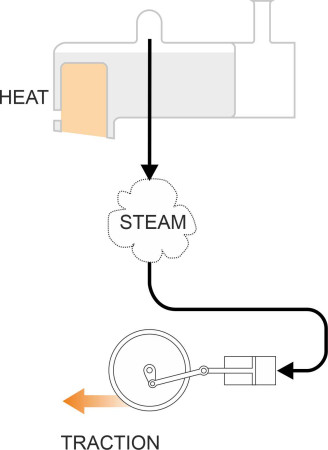
Figure 2
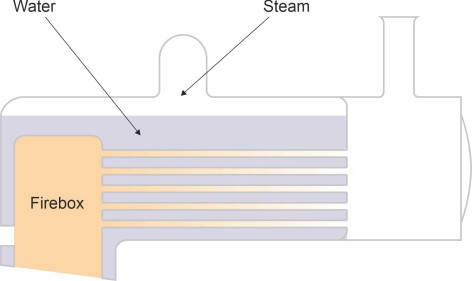
The boiler acts as an intermediate reservoir containing several tons of hot water and steam whose pressure must be watched carefully at all times regardless of what the loco is doing and indeed whether it is moving at all. This is why the fireman is important. The fireman’s job is not merely to shovel coal into the firebox, but to anticipate the steam that the driver will need to power the loco several minutes ahead, and to manage the boiler water level and coal burn rate accordingly. Steam mustn’t be wasted, otherwise the train may be forced to slow down to avoid running out of water before it reaches its destination. Steam is wasted if the coal burns too quickly, because the boiler pressure will rise and the safety valve will open, letting steam escape to the atmosphere. On the other hand, if the coal burns too slowly the pressure in the boiler will fall and the loco won’t be able to haul anything. Above all, the fireman must keep the level of water in the boiler sufficiently high to cover the top of the firebox (figure 2), otherwise the casing can melt allowing steam and water to burst rearwards into the cab [23]. Finally there is no ‘on-off’ switch: a steam loco takes half an hour in the morning to fire up before it can do any useful work. In the evening, it takes a while to cool down so the ashes can be raked out and the boiler tubes cleaned ready for the next day.
So the fireman needs to know the speed limits and gradients located along the route, and works closely with the driver to keep to the timetable. In fact, during the last century, becoming a fireman was often regarded as a first step towards a driver’s job [26]. By today’s standards, both jobs were arduous. The cab was noisy, dirty and uncomfortable, and the crew were exposed to extremes of heat and cold. Once qualified, the driver had to cope with a temperamental loco, coal of variable quality, and soot accumulating in the boiler tubes during each journey. To keep to schedule, he needed to judge carefully when to brake and accelerate the train, and maintain concentration for long periods looking out for signals and speed restrictions in fog, snow and rain.
Interestingly, there are two ways of controlling the speed of a steam loco, via two separate controls that work in different ways. The first is the regulator. The regulator valve is located in the dome on the top of the boiler (figure 3), and it controls the flow of steam from the boiler to the cylinders [17]. A common configuration is the slide valve which gives precise control by throttling an aperture. It effectively determines the pressure of steam available to the cylinders where the energy of steam is converted into mechanical thrust to drive the engine forward. You can think of it as a power-limiting device that has an overall effect on the engine’s performance. The regulator is closed when the train is halted at a signal or a station.
Figure 3
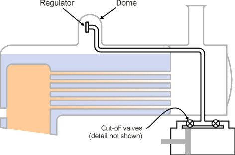
The second form of control takes place through cut-off valves that act separately on each cylinder. A cut-off valve doesn’t affect the pressure of the steam but rather the amount in the sense that it determines the time interval during which steam is admitted to the cylinder with every piston stroke. It opens at the beginning of the stroke, allowing steam into the small cavity between piston and cylinder. The pressure of the steam forces the piston to move away down the cylinder, while the steam itself expands into the growing cavity. At some intermediate point, the ‘cut-off’ point, the inlet valve closes and the steam already present continues to do its work, expanding against the piston until it reaches the end of its power stroke. By delaying the cut-off, the driver increases power by allowing fresh steam to continue entering the cylinder for a greater part of the stroke, although this steam is used less efficiently because it is exhausted to the atmosphere at the end of the stroke before undergoing complete expansion - some of its energy is lost to the outside world.
So in principle, a steam locomotive driver can control the speed in two different ways (a) by opening and closing the regulator, or (b) by increasing or decreasing the cut-off. Within limits, these procedures give similar results [27]. In practice, however, the cut-off gives much less precise control at low speeds and to move the loco from a standing start the regulator is used. First, the cut-off is opened to its maximum extent. Then the regulator is opened by a small amount, which produces a restricted the flow of steam between the boiler and the cylinders. The restricted flow ensures that the driving wheels don’t slip and damage the rails. As speed rises the regulator is opened wider until the desired working speed is reached, when the driver will normally leave it wide open for efficiency [19] and shorten the cut-off to maintain the speed at the target value. From this point on, power is controlled through the cut-off. To climb a grade, the cut-off is lengthened to get extra power, while on a down-grade, when the speed is likely to rise of its own accord, the driver will shorten the cut-off to reduce steam admitted to the cylinders; the process is called ‘linking up’ [21].
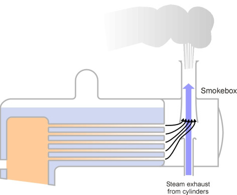
Meanwhile, the fireman is working alongside the driver to balance the energy flows. The balancing process works on two distinct time scales. In the short term, the process is self-regulating. When the driver increases the cut-off, more steam is admitted into the cylinders, and when it is exhausted at the end of each power stroke it still has residual pressure above atmospheric and blasts into the smokebox at the front of the boiler. The smokebox is designed to use the exhaust ‘puff’ to draw hot gases from the fire bed through the boiler tubes by a process of entrainment (figure 4). In turn, the combusting gases are replaced by fresh air sucked behind them into the fire bed, where the additional oxygen increases the burn rate for any given area of grate (you may have noticed that in a sense, the steam loco is using energy left over in the exhaust to boost combustion through a kind of feedback loop, a practice that is echoed in the ‘turbo’ unit supplied with many motor cars today). So in a nutshell, the lengthened cut-off causes the coal to burn faster and helps to maintain steam pressure. Conversely when the loco slows down the burn rate together with the steam pressure is reduced. So to some extent, the system compensates automatically for variations in the work rate demanded from the engine.
Figure 4
But in the longer term, if the loco continues to work harder, the fireman must help by adding more coal, and since it can take a while for heat energy to build up in the boiler, the stoking must be done well in advance of the time it is likely to be required. And what happens if the fire is stoked up and the driver decides he does not want power, for example, if the engine is halted unexpectedly at a signal? The stoking process can’t be reversed so the steam pressure will build up and eventually steam will be ejected through the safety valves and go to waste. This can sometimes be avoided if the water level is low, because the crew can add fresh water which will act as a reservoir, absorbing heat energy for a while. The water must be forced into the boiler against the prevailing boiler pressure, and in most steam locos this is done through a device called an injector. The injector works by entraining water in a steam jet drawn from the boiler itself and needs no mechanical power to drive it - a fascinating device in its own right (see for example, [18]). Before the steam injector was invented, it was necessary to use a pump, which didn’t work when the loco was stationary [24].
An explosion isn’t the only risk for the crew. If for any reason the blast in the smokebox fails to do its job, burning gases from the firebed are not drawn forward through the boiler as they should be, and may shoot into the cab round the edge of the fire door. Blow-back is a hazard for the crew, for example, when the loco enters a tunnel, when the sudden increase in atmospheric pressure around the front of the boiler can reduce the exhaust blast from the chimney sufficiently to disrupt the entrainment process. So a blower is provided to induce a vacuum in the smokebox when required [25]. This and several other hazards are well documented in [16] and [22].
The diesel engine
It seems that a steam locomotive needs two people to make it work and a fair degree of skill to make it work efficiently. But in one respect at least, it is a simple machine: the boiler delivers power to the wheels directly, with no clutch or gearbox for the driver to worry about. It does this through the pressure of steam acting on the pistons (figure 5), and the thrust is about the same regardless of how fast the loco is moving and even if it is standing still. So if the train has to stop for any reason it is not difficult to get it moving again, because a high tractive effort - the force that propels the vehicle along the track - is always available, and in fact it is only too easy for a steam engine driver to spin the wheels and damage the rails.
Figure 5
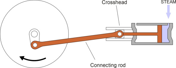
Figure 6
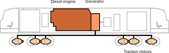
A diesel locomotive is different. The source of power, the ‘prime mover’, is an internal combustion engine which, like a steam engine, has several pistons, but the transmission of power from the pistons to the wheels is more complicated. Each piston is energised by the burning of diesel fuel sprayed into the column of air trapped in the cylinder. It’s the oxygen in the air that allows the fuel to burn. The column must be greatly compressed to squeeze the maximum amount of air into the cavity above the piston crown; compression also heats the fuel mixture and causes it to ignite. When the crankshaft is not rotating, the engine cannot draw in air, and it can’t do any work. To haul a train, it must be rotating at a certain minimum speed. And the faster the speed, the greater the output until it peaks at something in the region of 1000 revolutions per minute for a railway locomotive. This is much too fast for the wheels, so the engine must be geared down. But the output is too large to be handled by a conventional gearbox. Some railway diesels use a hydraulic transmission that produces much the same effect as a gearbox but more smoothly and with less wear and tear. German manufacturers have been particularly successful with this approach. Others prefer to connect the diesel engine to a generator, which converts the mechanical output into electrical power, and use the output current to drive one or more electric motors to provide the tractive force (figure 6). Since an electric motor can be configured to provide high torque at zero rpm, it overcomes the problem of starting from a standstill. And it is all controlled by a single lever in the driver’s cab.
An elegant concept? Perhaps. But it took many years of development to make the engine, the generator and the electric motor work together in harmony. The first reliable system to be controlled by a single lever was developed in the USA in 1914 by Hermann Lemp of the General Electric Company. He established the control principles that came to be used widely throughout the industry, and in particular, the principle that any particular setting of the control lever should result in a specific amount of power delivered to the wheels regardless of the locomotive speed. Power, not tractive effort or pull: it’s an important distinction. An internal combustion engine will operate best over a particular range of rotational speeds (revolutions per minute, or rpm). Within this speed band, the proportion of chemical energy in the fuel that is converted into mechanical energy is close to the maximum possible; conversely, the minimum amount of fuel is wasted. When the engine speed increases, there are more combustion cycles per minute and more fuel is burnt, creating more energy per unit time. When the speed decreases, the output rate falls. Hence the aim of a diesel-electric control system is to vary the power output by increasing or decreasing the rpm within the optimum speed band.
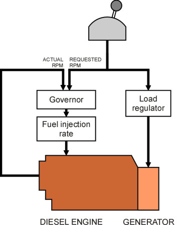
So how does this work in practice? The driver pulls the throttle lever through a graduated series of steps corresponding to gradually increasing power levels. Most have eight distinct ‘notches’. The lever conveys two sets of control signals, one to the diesel engine and one to the generator (figure 7). The first is channelled through a governor that sets the speed of the diesel engine: it does this by comparing the actual rpm with the value assigned to the current notch and where necessary, increasing or decreasing the fuel supply rate. The second set is routed through a load regulator, a variable resistor that changes the field current in the generator to increase or decrease electrical power output fed to the traction motors. This ensures the system as a whole is producing approximately constant power regardless of traction motor speed.
Figure 7
This was the system that dominated diesel-electric control until the 1960s. Since then the mechanical and electrical hardware has evolved considerably. First, the DC generator was superseded by the AC alternator, while the underlying control principle remained the same insofar as the driver was concerned: the throttle settings effectively controlled the power delivered to the locomotive wheels. It wasn’t until the 1980s, when the DC traction motors together with the electro-mechanical switchgear were replaced by AC motors and solid-state circuitry, that other more sophisticated control schemes became possible. For example, each throttle notch could be identified with a given level of tractive effort rather than power output, which in some ways makes control easier and more direct. This was the case for example with the UK Class 50 freight locomotive introduced in 1967 [12].
The electric locomotive
Compared with a diesel or steam locomotive, an all-electric locomotive is lighter, faster and more efficient because it doesn’t have to carry fuel or burn it in a heavy container. And from the driver’s point of view, the control logic is simpler and more direct, at least in principle. There is still a power control lever, but on modern vehicles the lever setting is scanned by a microprocessor and modified to take account of the vehicle’s present speed, the track gradient, and the current state of the signals and any relevant speed restrictions so that in effect the driver has the equivalent of an aircraft ‘fly-by-wire’ system in which every action is overseen and moderated by a computer positioned between the driver and the machinery to be controlled. It is now possible for the driver to request a particular speed on a dial and let the computer do the work of setting up an appropriate programme of acceleration or braking until the target is reached: it produces a similar effect to the cruise control system installed on many automobiles [14].
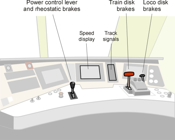
So the driver’s console looks more like a computer workstation than the apparatus you might expect for directing heavy machinery (figure 8). On many vehicles the control lever - about the size of a computer joystick - manages both acceleration and rheostatic braking and also acts as a reversing lever. The remaining controls are auxiliary functions such as the horn, vigilance alert button or foot-pedal, and a bank of switches for operating the wipers and headlights together with the lighting, heating, ventilation and door-opening locks for the passenger coaches. A computer display screen tells the driver how fast the train is going and how the traction motors are performing, while a second screen shows what is happening on the track ahead, namely the track signal aspects and any relevant speed limits.
Figure 8
From all this you might imagine that the driver’s task has been reduced to pressing buttons, one to make the train move and one to make it stop. In some ways you’d be right, because like an airline pilot, the driver has become a supervisor whose role is to monitor the performance of the vehicle, keep an eye on the track, and communicate with the line manager in charge of train movements. When faced with this kind of role, it’s not easy to stay alert. That is why some kind of vigilance warning system is needed. The traditional solution is the ‘dead man’s handle’, a spring-loaded lever or foot-pedal that the driver must push down and keep depressed at all times when the train is moving. The system will automatically stop the train if the driver loses consciousness and slumps away from the console. But it’s not foolproof, and on newer vehicles it has been replaced by a lever or push-button that the driver must press and release at frequent intervals. Even this isn’t foolproof: though barely awake, a driver might work the lever sufficiently to keep the train going for a considerable time. A high-speed passenger train requires something more sophisticated, and the microprocessor once more comes to the rescue, monitoring the console to check that the driver is actually adjusting the controls from time to time in a meaningful way.
Managing the train
But this raises an obvious question. When linked to a CCTV camera and programmed with image-processing software, a computer could in principle analyse the visual scene in front of a train and manage its progress - and some would say, manage it more reliably than a human driver. This is already being done for motor cars, and indeed, there are many light railways around the world where the trains operate entirely under automatic control. So why does a train need a driver at all? The answer seems to be that, for the time being at least, events will occur on a mainline railway that are beyond the control of the operating staff and outside the range that can presently be predicted or managed through computer software. For example, the track may be damaged by a landslide, or a lorry may come crashing down the embankment. More often, it will be a minor incident such as a defective signal or a fault on the train itself such as a red light indicating that a passenger coach door is not properly closed. A human driver can interpret what is going on, act as a channel of communication with the line manager, and judge how to proceed in circumstances where a computer will run out of ideas.
Rules and regulations
Given the heavy responsibilities involved, it is not surprising that when joining a railway company each candidate is required to undergo an extensive training course before being allowed to drive a train. The course starts with the company’s aims: what the railway is for, what the company is trying to achieve and what constitutes an acceptable service. There is a commonly accepted scale of priorities that govern how a railway should be managed and operated, from which the rest follows. Broadly in order of importance they are:
- Safety,
- Keeping to time,
- Passenger comfort,
- Fuel economy,
- Wear-and-tear on track and vehicle.
Although there are variations, safety always comes first, and in day to day operation, the most important requirement is to conform to trackside signals and speed restrictions. Readers will know that from time to time a driver will get into trouble by passing a red signal. Incidents involving a Signal-Passed-At-Red (SPAD) are surprisingly common. Every year in the UK, there are many hundreds of such incidents, mostly as a result of defects in the signalling system itself, because a malfunctioning track circuit causes the signal to reset to red by default, often when there is a train approaching with no possibility of the driver being able to stop in time. In fact, with permission from the signal control centre, a driver is expected to pass a red signal if it’s known to have failed and the fault can’t be corrected immediately. On some occasions the driver may be authorised to drive ‘on sight’: in other words, to manoeuvre the train in a confined area such as a freight yard without any signal control at all, taking account of any possible path conflicts, like a tram moving along a city street.
The remaining priorities are concerned with different aspects of performance. Drivers are expected to keep to schedule and make up for any time lost owing to unforeseen delays, but on the other hand it is strictly forbidden to break speed limits, which provide essential protection for example on a sharp bend where excessive speed could derail the train. And for the sake of passenger comfort, acceleration and braking should be kept within modest limits: smooth driving is not only reassuring for passengers but it also saves fuel. In the case of freight trains, fuel economy is particularly important, and it can be improved markedly by promoting driving techniques that are designed to conserve momentum [5].
The principles are not hard to understand, but anyone who sets out to become a train driver may be daunted by the rules and regulations one must learn beforehand. Most railway operating procedures are spelt out in detail in the company’s Rule Book. The most important ones govern how drivers should respond to trackside signals, what to do when stopping at a railway station, or when shunting wagons in a freight yard. There are also rules about the preparation of a train before it is driven out of its siding, and rules about powering down and switching off (‘disposal’) when it is returned after duty. Others are concerned with what the train driver must do if things go wrong: as far as possible, drivers are told what to expect and how to deal with common situations. The most common ones involve faults on the train, or defective track equipment such as track circuits, signals and turnouts.
The rules have accumulated over many years. They are intended to prevent railway staff from repeating mistakes that have led to trouble in the past, by establishing a systematic toolkit of procedures intended to cover almost all eventualities, within a strict disciplinary framework. It is in the nature of railway operation that employees are accountable - there must be an ‘audit trail’ that allows investigators to determine who is responsible if anything goes wrong. Unlike the road system, no ad hoc movements are allowed. You can’t just hop into the cab and drive a locomotive up and down to see whether it is working properly. Every time a railway vehicle is put into motion, the driver must have a movement authority, a paper docket or electronic record that signifies permission to access the track.
Starting and stopping
It takes about a year to qualify as a driver, and before being allowed to work a particular service, the candidate must spend several weeks under the supervision of an experienced driver learning the signalling system, the gradients, the speed limits, and the stations along the route. A great deal of emphasis is placed on smooth braking and acceleration together with sensible choice of speed, but for the moment we’ll concentrate on just two basic operations: starting and stopping.
When starting a loco-hauled train the driver will have two things predominantly in mind. The first is that, as we saw earlier in Section R0204, one should apply power gradually and take up the slack in the couplings before pulling away [4]. In the USA, it is not unusual for a freight train to have two or three locomotives jointly hauling a formation of 150 wagons that extends over a distance of 2.5 km (1.5 miles). When the driver pulls the power lever, the leading locomotive will travel 20 metres (75 feet) before the last wagon moves at all [1]. The second area of concern is grip. The locomotives together must develop enough friction between wheel and rail to overcome the total train resistance, and the driver must allow for a reduced coefficient of friction in bad weather or whenever the rail surface is contaminated. Regardless of the conditions, grip is maximised when the speed of the wheel tread flowing through the contact patch is slightly faster than the train speed [20]. On the other hand, the coefficient of friction falls sharply when the wheel spins (see Section R1717), so a driver who is controlling traction directly through the throttle must use the power sparingly. A train will accelerate more quickly (and with less risk of damage to the track) if the powered axles are fitted with traction control, otherwise known as ‘anti-slip’. On some vehicles, slip is detected by a radar unit that measures the relative speed of the ground surface beneath the train. A microprocessor then works out what the motor speed should be if there were no slip, and compares it with the actual speed of each motor output shaft measured through a magnetic probe. The power is reduced whenever the wheel slip rate exceeds a threshold value.
Much of what can be said about traction control applies to braking control too - when a wheel slides along the rail some of the retarding force is lost, and therefore drivers allow for the possibility of water, ice or debris that could greatly increase the stopping distance when, for example, approaching a red signal. Low-adhesion driving is an important element of driver training, which may even include a ‘skid pan’ test on oiled rails. But the braking process is more complicated than the traction process because as explained earlier in Section R0816, a deceleration sequence can involve different modes of braking at different stages. In order of increasing severity, they are [5]:
- Train resistance
- Rheostatic braking
- Mechanical braking
The first braking mode relies on the intrinsic resistance to motion of the train to produce a gradual deceleration without any brakes applied at all. The second relies on rheostatic brakes, which are confined to the power bogies. Rheostatic brakes yield a smooth retarding force whose effect is most pronounced when moving at speed: it falls away to zero as the train approaches a standstill. It’s the third mode, mechanical braking, that brings the train to a halt, and operators distinguish between three different levels of intensity: light braking, full service braking and emergency braking. The mechanical brakes are either disk brakes or shoe brakes, triggered by an air pipe that links all the vehicles in the train. On some high-speed trains, the driver can apply both rheostatic brakes and mechanical brakes through a single lever that invokes an appropriately phased sequence under microprocessor control [10]. On older trains, the two types have separate control handles, and the driver can apply them independently. The ability to brake the loco on its own is important for freight trains, which are tricky to manage, and drivers learn various techniques for avoiding longitudinal impacts among the wagons that can damage couplings or bounce a wheelset off the rails. For example, when it becomes necessary to brake the train after moving along at a steady speed, it’s useful to bunch the wagons together well in advance, by applying minimal air braking about 20 s before the service operation [6].
Speed control
So much for starting and stopping. Now let’s think about what happens in between. Ideally, a train will spend most of its journey moving briskly along at a steady speed, because any variation - speeding up or slowing down - is expensive [7]. Every time the brakes are applied, the train dissipates kinetic energy that must be replaced by consuming more fuel. Braking also contributes to wear of the disk pads, wheels and rails, and for a high-speed passenger train, it adds considerably to the journey time. If the train is forced to slow down for any reason, as shown in figure 9 it loses time (a) while decelerating, (b) while travelling at reduced speed, and (c) while regaining its original speed. From a standing start, a high-speed train takes about 5 minutes to accelerate to 300 km/h [8].
Figure 9
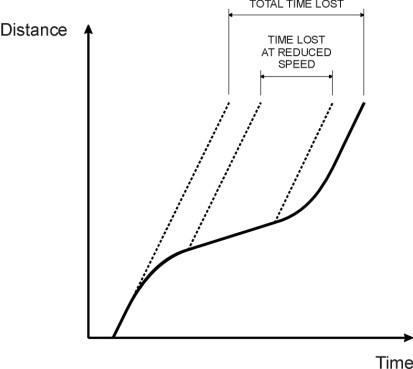
Figure 10
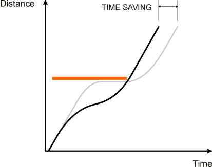
Paradoxically, a train can be delayed by travelling too fast at the wrong moment as shown in figure 10. This often happens on the approach to a red signal. If it were possible to predict the future the driver would brake earlier rather than later so that the train arrives at the signal and is still moving as it clears to green. More generally, a driver tries to anticipate speed limits, which in the UK are shown on circular disks beside the track, and where possible to allow the natural resistance of the train to slow it down in advance so that less braking effort is required.
For long stretches of a railway journey, the driver is expected to maintain a target speed consistent with the timetable. But at various place along the line, there will be speed restrictions associated with turnouts, curves in the track alignment, passenger stations, and maintenance works. Ideally, the driver will adjust the speed of the train to match as accurately as possible the limit on each section of track, and modern trains are equipped with a form of cruise control that does this automatically [14]; the driver needs only to adjust the speed dial to re-set the target speed for each section. There is a splendid description of a typical run in the cab of an all-electric 225 km/h express passenger train equipped with an early form of cruise control, travelling from London to Leeds in 1990 [15]. It explains how the speed limit, 15 mph (25 km/h) on the exit from Kings Cross station, rose in stages first to 45 mph (72 km/h) then 65 mph (105 km/h) and so on for several kilometres until the train was finally allowed to accelerate to cruising speed. The account goes on to describe how the driver coped with unexpected red signals, maintaining the schedule by continually juggling with the speed setting and brakes to recover lost time. As a passenger, one rarely notices what is going on, because the driver is careful to avoid longitudinal jerks, for example by easing off the power lever before passing through a neutral section where there is no power from the overhead wires.
Twenty-odd years after this account was written, engineers worked out how to ensure that the driver was carrying out the speed adjustments correctly. Different varieties of intermittent speed control are now in use [13], all of which are designed to achieve the same effect: if the train exceeds the designated speed by a few kilometres per hour an electronic system in the driver’s cab issues a warning, and above a certain threshold it applies the brakes and immobilises the train. For this to work, the train must ‘know’ what restriction if any happens to be in force at each point along the track. In France, two different methods are used. On some lines, an electromechanical ‘crocodile’ consisting of a metal blade mounted in the centre of the track makes contact with a metal brush mounted on the loco. TGV lines operate with electronic balises. A balise is a radio beacon containing inductive loops that communicate with an antenna mounted on the vehicle. In other countries such as Germany, trackside magnets interact with an electromagnet bolted to the train chassis. Systems of this kind reduce the likelihood of the driver over-running a signal or approaching a known hazard too fast, but they only work at places where they are installed and don’t influence what happens in between. Continuous speed control, as developed originally by Swedish and Norwegian Railways, also relies on trackside units that transmit coded information about (a) speed restrictions and (b) signal status, but in addition record the presence of the train and its speed. The cab contains a receiver and a computer, which works out a suitable speed profile through to the next unit and checks whether the train speed complies with the requirements at all points along the profile [13].
So far we have concentrated on passenger trains, where punctuality is crucial because small delays can propagate throughout the system and disrupt the timetable. Timekeeping is important for freight trains too, but it’s even more important to avoid longitudinal shock waves that might disable the train and bring the whole railway line to a halt. We have already seen that slack in the couplings needs careful handling so that the rearmost wagons don’t break away when the train starts off. On an uphill grade there is an additional risk of runaway wagons rolling back downhill into the path of another train. On a downhill grade, it’s a derailment caused by a compressive shock that poses the main threat. In the days of steam, the only brakes available were those on the engine, the tender, and the brake van (caboose), so before reaching the descent, the driver would stop and let the guard apply the brakes to some of the wagons in order to keep the train under control. On modern trains with pneumatic brakes on every wagon, downgrades are less hazardous, but it is still common practice for the driver to slow down on the approach to reduce the demands on the braking system [5].
Things are more complicated still on an undulating track. For example, when passing through a valley the leading part of a train crosses the lowest point first and then enters an uphill grade. Initially, the couplings will be in compression but as the loco ascends, the couplings in the leading part will switch to tension while those in the remainder of the train will be in compression. Eventually, all the couplings will undergo a stress reversal after passing through the valley bottom [1]. In a complicated situation like this a driver might use ‘power braking’ or ‘stretch braking’ to keep the couplings taut throughout, a technique that was common in the USA until the early 1980s and is still practised in Australia, especially on freight trains hauling a mixed formation that includes empty wagons [3]. The air brakes are partially applied on all wagons/coaches but not the loco. Not surprisingly, drivers in many countries nowadays undergo training on simulators before being assigned to heavy freight trains [2].
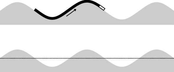
Incidentally, in undulating territory a long train needs less power per wagon than a shorter one. In figure 11, a locomotive highlighted in white is shown hauling a formation over a series of peaks and troughs. On an uphill grade, the loco must provide extra traction to overcome the gravitational pull on the wagons. But once the loco reaches the peak and begins to descend, this is partly counterbalanced by the gravitational component of the leading vehicles on the downhill side acting in the forward direction. To put it another way, the path traced out by the centre of mass of the train, as shown by the dotted line in the drawing, does not have to rise and fall to the same extent as would the path of a single wagon on its own. In the extreme case shown in figure 12, the length of the train equals the wavelength of the undulations. Hence the centre of mass follows a level path, and the energy needed to overcome gravitational resistance is zero: the train might just as well be travelling on level ground. In theory, there are circumstances in which the journey time can be shortened by adding more wagons to the train.
Figure 11
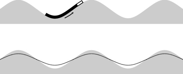
Figure 12
The railway environment
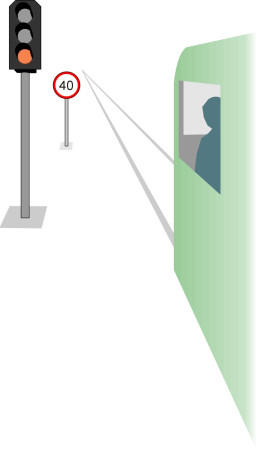
On a dual-track railway line, the layout of the signals and speed limit signs is easy to understand. Throughout most of Europe, trains drive on the left. In the USA and the USSR, they drive on the right. In all cases the signals are positioned on the ‘nearside’ of the track to which they refer, i.e., the left in Europe (figure 13). But if you have ever stood on the track outside a mainline station you will know it is an alien, forbidding environment. The signals are mounted on gantries that span across several tracks. Amid the confusion of turnouts and signals it is hard to predict where the next train is coming from, and track maintenance operations must be carefully organised to avoid exposing the crews to danger. For much the same reason, a novice driver must spend time working the route with an experienced driver in the cab to learn the signals and the ‘roads’ to which they apply.
Figure 13
Unfortunately, it’s still possible to miss a signal and put your train in the path of an oncoming express as happened in the notorious disaster at Ladbroke Grove in London in 1999. The crash occurred 5 km from the Paddington mainline terminus. An HST 125 express passenger train operated by Great Western Trains collided almost head-on at a combined speed of over 200 km/h with a 3-car diesel unit 165 operated by Thames Trains that was switching tracks as it made its way out of London, and crossing the path of the incoming express. In all, 31 people were killed and 260 injured. A critical factor was the failure of the outbound train to stop at signal SN109 some way upstream. It didn’t help that the track layout on the approach to Paddington is unusually complex: the signal had been passed at red 8 times in the previous 6 years [11].
In principle, all such collisions could be prevented by safety systems that have been available for decades. Some systems provide warnings to the driver of a potential conflict, while more advanced systems trigger an emergency braking sequence that brings the train to a halt. There has been much controversy in the UK about the cost of upgrading from one kind of system to the other and whether it is worthwhile (possibly, there are other ways you could spend the money and save more lives). But the arguments have since receded with the decision to expand the high-speed network. At a speed of 300 km/h, a driver cannot read trackside signals at all - the signals must be displayed in the cab and the control must be virtually automatic. In any case, the traditional ‘block’ system of signalling is becoming obsolete. The block system is a common-sense approach that relies on the notion of dividing the track into sections and working the signals so that two trains cannot occupy the same section at the same time. But when a high-speed service is introduced on an existing line, the distance required for a train to stop is spread over several blocks and signalling becomes complicated. It is better to have virtual ‘blocks’ that move along with the trains.
A new control system called ERTMS (European Rail Traffic Management System) is now being rolled out in several countries across Europe, partly with the aim of unifying control protocols across national boundaries, and partly to provide a platform for advanced forms of moving block control that dispenses entirely with trackside signalling. The system can be configured to operate on different levels [9]. At the lowest level it continues to use track circuits to detect the location of each train together with block signals, in other words, a conventional track set-up. But communication with trains takes places through balises mounted on the track, and each train is equipped with an on-board computer. At the highest level, the train location is provided by the vehicle itself and communicated to the control centre by radio. There are no conventional track circuits or signals, and moving block control effectively allows a reduced gap between trains so that more trains can use the same length of track at any one time.
Conclusion
We are now approaching a time when the idea of ‘driving’ a train has lost its traditional meaning. There may well be a highly-qualified technician in the cab, but the role of the technician doesn’t necessarily entail handling the controls or even making decisions about braking, acceleration or speed. In principle, an intelligent computer system can work the controls to meet the timetable and even replace the driver’s function of observing the track ahead: one of the notable properties of computer software is that it evolves in cumulative fashion, as successive generations build on what has already been ‘learnt’, so that capabilities and functions that seems far-fetched today have a habit of emerging as reality tomorrow. In any case, when travelling at 350 km/h neither a train driver nor a computer-driven image processing system can see anything sufficiently far ahead to serve any useful purpose. The train of the future will be a robot presided over by a manager whose job is to make sure the robot is working properly, and only to take control when the technology breaks down. The ‘seeing’ will be done in advance of the train’s arrival by trackside CCTV surveillance cameras - or even an aerial drone flying ahead, just above the track.