M.0505
Steering gear
A small boat is easy to steer. You can swing the tiller to the right or left and the boat changes its path as if following the movement of your hands. But a larger vessel is less easy to manage. Because of its inertia, a passenger liner or a supertanker takes time to respond to the master’s steering commands. Much depends on how fast the ship is moving, because the forces that make it turn are generated by the water flowing past the rudder. When the ship slows down, the forces weaken and the ship becomes erratic and difficult to control. In this Section, our aim is to investigate different kinds of steering gear, and to see how it works in cooperation with the hull to make the ship change course.
Steering gear
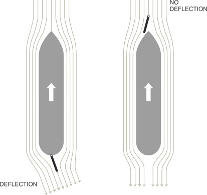
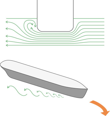
You steer a road vehicle by swivelling the front wheels, so the nose swings in the direction you want to go, and the rest of the body follows on behind. With ships, it’s the other way round: the stern swings first because that’s where the steering gear – usually a single rudder - is mounted (figure 1). Why the stern? There are two reasons for this. First, a rudder works by deflecting water, and the reactive force pushes the rudder blade to the right or left depending on its angle relative to the direction of motion. But this can only happen if the fluid particles are free to deflect at an angle to the ship’s longitudinal axis as shown in the first diagram in figure 2. If the rudder were placed in front, the water couldn’t do this; regardless of the rudder angle it would divide more-or-less equally around either side of the hull. Second, a rudder works best in the slipstream of the propeller: here the fluid is moving faster and producing more ‘lift’ even when the vessel itself is moving at a low forward speed.
Figure 1
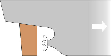
Figure 2
The rudder
The origins of the rudder can be traced back to a simple device used by mariners at least five thousand years ago: an oar pivoted near the stern. Attached to the hull was collar that acted as a fulchrum through which the oar passed so the helmsman could hold it steady and adjust the angle of the blade. For a right-handed person, the most convenient location for a steering oar was on the starboard side, and indeed the history books tell us that the term ‘starboard’ derives from the words ‘steering’ and ‘board’. They also say that to avoid damaging the oar, ships would dock with the opposite side against the harbour wall, hence the term ‘port’.
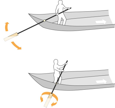
The history books don’t tell us much about the steering technique used by the ancients, but in principle there are two ways to get a purchase on the water. The first is to swing the oar to either side as shown in the upper part of figure 3. The second is to twist the oar around its longitudinal axis as shown in the lower part of the Figure. Either action changes the angle of the blade relative to the water flow, thereby generating a pressure difference between the two faces to steer the vessel to port or starboard as desired. It appears from early manuscripts that the steering oars attached to vessels such as the Viking longboat projected almost vertically into the water and hence the twisting action was the one actually used. But the helmsman on a Chinese ‘Dragon boat’ racing canoe, where the steering oar still survives today, uses a combination of both [1]
Figure 3
For centuries the steering oar was only practicable way to control a ship. But in rough water, the impact of sea waves made it hard to manage, and subsequently the steering oar evolved into a rudder hinged on a more-or-less vertical axis at the stern, which enabled more precise and dependable control (figure 4). The device probably originated in China, where in the 2nd millenium BCE, the world’s largest ships were being built. It wasn’t until the 13th century that the idea arrived in Europe, where it stimulated the development of sailing ships of extended range and capacity that could carry cargo more quickly over long distances [17].
Figure 4
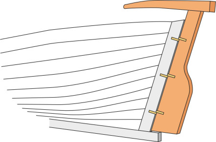
Since the rudder is vital to safe navigation, marine architects devote considerable attention to its size and shape, together with the way it is attached to the hull. There are several different arrangements: figure 5 shows the ones most commonly in use today. The rudder on the left, sometimes called the ‘simplex’ type, can still be found on older ships. The blade pivots on two bearings, one at the top and one at the bottom. The lower bearing is called a pintle: it carries the weight of the rudder and transfers it to an arm projecting underneath the propeller from the rear of the keel, which gives the rudder blade protection from underwater obstructions. The axis of rotation is at the leading edge of the blade (this is this axis that marine architects use to define the rear ‘perpendicular’ from which the ship’s length is measured). Bolted to the top of the blade is the rudder stock, a strong steel bar that pivots around the same axis to make the rudder swing from side to side.
Figure 5
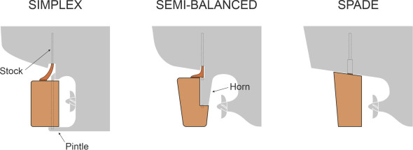
In the second configuration shown in figure 5, part of the blade projects forward of the axis of rotation; the centroid is closer to the axis so less torque is needed to rotate the blade and hold it against the pressure of the water during a turn. It is known as the ‘semi-balanced’ type. Here, the pintle is carried on a horn projecting downward from the hull. The third variety has been called the ‘spade’ rudder and since the leading edge projects forward of the axis of rotation, this too is a semi-balanced design. The blade is mounted on a vertical stock that projects downward from the underside of the hull; there is no supporting pintle. Spade rudders have become more common recently, especially for twin-screw vessels where two rudders are needed side by side, each within the slipstream of one of the screws.
Rudder geometry
Although vital, the rudder is a nuisance because it adds to the vessel’s weight, it increases the overall drag, and it is vulnerable to damage. So the designer aims for the smallest possible size consistent with the need for safe steering. If you think of the rudder as a wing projecting vertically into the water, the lateral thrust it can generate is proportional to its area viewed from the side. For larger vessels, one particular organisation, Det Norske Veritas, recommends a minimum area \(A\) expressed as a proportion of the total lateral area of the submerged hull. The hull area is taken as the draft \(T\) times the length \(L\), and the ratio \(A/LT\) is given by the following formula [6]:
(1)
\[\begin{equation} \frac{A}{LT} \quad \ge \quad 0.01 \left[ 1 + 25 \left( \frac{B}{L} \right)^{2} \right] \end{equation}\]where \(B\) is the ship’s beam. For many ships the right-hand side works out at roughly 0.015, meaning that the rudder should amount to 1.5% of the total area. For the cargo ship Cecily mentioned in Section M1115, the formula implies a rudder area of about 26 m2.
This is tiny. How can such a small device make the ship turn? Personally, I find it helpful to compare the function of a rudder with the function of a car’s front wheels when it travels round a curve. Putting aside the fact that they support much of the vehicle’s weight, the front wheels serve two distinct purposes. First, in conjunction with the rear wheels they supply a couple that makes the chassis yaw, in other words, they make the vehicle rotate, continuously changing its direction of motion as it rounds the curve. Second, they provide much of the centripetal force needed to hold the vehicle on its curved path. The force needed to rotate the body is quite small, while the force needed to hold a curved path is much the larger of the two and it increases as the square of the vehicle’s speed. In theory, if the tyres didn’t grip the road very well, the car could rotate but continue to move along its original path in a straight line, skidding sideways off the road. In contrast, a ship’s rudder only has one function, which is to make the vessel yaw; this calls for a relatively modest lateral thrust, and as we’ll see later, the centripetal force is not supplied by the rudder at all.
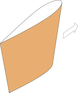
Nevertheless, to minimise weight and drag, the rudder should be hydrodynamically efficient. On a large vessel, this requires the cross-section to be streamlined as shown in figure 6. The streamlined profile both maximises the ‘lift’ and the range of angles over which the rudder will operate. The commonly specified maximum angle is \(35^{\circ}\), at which point most rudders ‘stall’: the flow breaks away over the leading edge and becomes turbulent, and the drag rises appreciably while the lift falls.
Figure 6
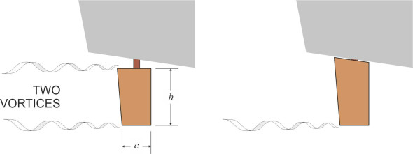
What about the shape in side elevation? We know that a wing or a hydrofoil will lose energy through vortices that curl around the wingtips. Such losses imply a reduction in lift, but the reduction is less pronounced if the wing is long and narrow: the higher the ‘aspect ratio’ of length-to-chord, the greater the lift. In practice a high aspect ratio is not possible in a ship’s rudder, which must be relatively short and sturdy in order to survive heavy seas and accidental impacts. But the designer can compensate by adjusting the gap between the top edge of rudder and the underside of the hull. A narrow gap removes one of the tip vortices and effectively doubles the aspect ratio (figure 7). Incidentally, the same is true of a ship’s sail: the gap between the bottom edge and the deck needs to be as small as possible so air can’t leak underneath.
Figure 7
Control mechanism
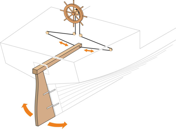
Traditionally, the device that controls the steering of any ship is called the helm. It can take one of several different forms. The simplest is a handle or tiller fixed to the top of the rudder that projects forward into the cockpit. It is widely used on sailing craft. To turn to starboard, the captain will call for ‘right helm’, and confusingly, whoever is at the helm must move the tiller to the left. The longer the tiller, the less the force needed to swing the rudder across and hold it there while the boat changes course. On a larger vessel this is not always practicable. A sailing ship needs continual adjustment to keep the ship pointed in the right direction relative to wind and waves. In a storm this is hard work, and you don’t want the tiller swinging from side to side and knocking the crew over. The alternative is a ship’s wheel connected to the rudder stock via two cables that effectively step down the ratio of wheel movement to rudder movement (figure 8). This makes the wheel easier to turn and also reduces backlash, so the forces on the rudder don’t tear the wheel out of the helmsman’s hands.
Figure 8
On a large ship today, the forces are greater still. Tankers, warships, and passenger liners need hydraulically powered steering gear to hold the rudder steady against fluctuating water pressures in a heavy sea. Even leisure craft have power steering – not only does it relieve the crew from physical effort but it can be linked to an auto-pilot system to keep the vessel on a steady course so the crew can get on with something else. So just how large are the forces involved? We know from dimensional analysis that the fluid forces acting on a lifting surface are determined by three parameters (the area of surface, its angle of incidence relative to the fluid motion, and its speed), so the lift and drag can both be estimated through empirical formulae that have a common structure. Examples are the lift generated by an aircraft wing, and the drag of just about anything moving through a fluid; you’ll find general formulae for both in Section F1817 together with an explanation of why they take on the particular form that they do. For a force acting on a rudder, we expect an equation of the form
(2)
\[\begin{equation} \text{Force} \quad = \quad \text{constant} \times \text{rudder area} \times \text{speed}^{2} \times \text{rudder angle} \end{equation}\]Here, we are interested in the force \(F_N\) acting at right-angles to the blade, and we will write it in the form
(3)
\[\begin{equation} F_{N} \quad = \quad C \rho A V^{2} \sin{\delta} \end{equation}\]where \(C\) is a dimensionless coefficient, \(\rho\) is the density of water, \(A\) is the rudder area, \(V\) is the speed of water flowing over the rudder surface, and \(\delta\) the rudder angle. The value of \(C\) must be determined empirically [12]; here, I’ll assume that if \(F_N\) is in newtons, \(A\) in square metres, and \(V\) in metres per second, a suitable value might be around 0.5. Then, if our cargo ship Cecily were cruising at 15 knots with the rudder angled at \(10^{\circ}\), we’d estimate the value for \(F_N\) as \(0.5 \times 1025 \times 26 \times (15 \times 0.5148)^{2} \times \sin{10^{\circ}}\), which comes to about 140 000 N or 140 kN. This is roughly equivalent to the weight of a double-decker bus.
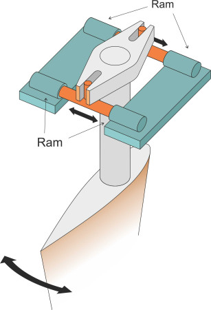
A robust power-steering system is needed to operate a rudder that is subject to forces of this magnitude. Usually it will comprise a hydraulic ram, perhaps with a second ram in reserve, but increasingly nowadays, the designer will specify two rams operating in parallel as shown in figure 9. Each ram is connected to a lever arm built into the rudder stock, and the whole mechanism operates in a horizontal plane. There must be sufficient ‘travel’ in the connecting link to allow for rudder angles within the usual range of \(\pm 35^{\circ}\). The motion of the rudder is not instantaneous. On a large vessel, it swings at a rate of about 3 degrees per second [15]. An IMO regulation called the ‘hard rudder test’ stipulates that the time to lay the rudder from 35\(^{\circ}\) port to 30\(^{\circ}\) starboard shouldn’t exceed 28 s [5]. Just think about this for a moment. When you drive a car through a chicane, you can swing the steering from left lock to right lock in a little over a second. On a ship, the equivalent manoeuvre can take nearly half a minute.
Figure 9
Other forms of steering
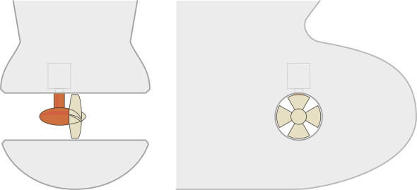
Unless a ship is moving forward at about 4 knots or more, the rudder won’t work, and the ship will need help to get in and out of harbour. Tugs are usually available to handle larger vessels, but manoeuvring under tow is an expensive and time-consuming process. To avoid delays, a passenger ferry may have thrusters fitted instead. A thruster is a propeller set in a tube aligned at right-angles to the ship’s longitudinal axis. It directs a jet of water sideways that makes the vessel yaw either to port or to starboard as required. As shown in figure 10, it is usually positioned close to the bow and sometimes there is one at the stern as well, so that if necessary, the two together can propel the ship sideways towards or away from the wharf. To provide adequate control, each should produce a thrust of the order of 0.1 kN per square metre of lateral area of hull below the waterline [4]. Such devices can only work when the vessel is moving slowly, because at cruising speed the water flowing around the bow deflects the jet against the hull plating and neutralises the thrust.
Figure 10
Many ships today are fitted with a more radical alternative: the main propeller drive is located in a ‘pod’ suspended below the hull that swivels around a vertical axis so it can direct thrust in any desired direction. It is a sophisticated and expensive device, but it has two benefits: (a) the rudder is no longer needed, and (b) the system can be rotated through \(180^{\circ}\) to act as a brake with no loss of directional control. A key problem is how to supply power from the engine to the propeller, and there are two possible solutions. The first requires a vertical drive shaft rather like the drive shaft in an outboard motor, which transfers torque from the engine output shaft inside the hull via two sets of bevel gears to the propeller shaft located in the pod underneath. The whole assembly is called an azimuth propulsor (figure 11). The second is a form of electric transmission. The engine drives a generator that supplies current to the pod, where a powerful electric motor drives the propeller shaft. This arrangement is known as a podded propulsor.
Figure 11
Finally, we come to the waterjet, widely used to power smaller, high-speed craft. Having covered the main features of waterjet operation earlier in Section M1405, we need only mention that the nozzle pivots from side to side, so it can deliver thrust across a wide range of angles. This makes a waterjet craft highly manoeuvrable, and since the thrust is more-or-less independent of the vessel’s speed, like the podded and azimuth propulsors, the waterjet works well in confined spaces.
How the steering works
Provided the ship is moving fast enough, the rudder will make it yaw to port or starboard as required. But unlike the wheels of a car or a train, it won’t hold the vessel on a curved path; it’s merely a lever that points the bow in the required direction. Most of the work is done by the hull itself.
Forces on the vessel
To understand the dynamics, we need to look more closely at the forces involved. Using the coordinate system shown in Figure 2 of Section M1115, we attach three perpendicular axes to the origin at the centre of mass: (i) the \(x\) –axis points forward parallel to the ship’s longitudinal axis, (ii) the \(y\)-axis is transverse positive to starboard, and (iii) the \(z\)-axis is vertical, positive downwards. The result is a framework for measuring not only forces but the distances, speeds and accelerations that characterise the ship’s motion. There are six possible motions as indicated in Figure 3 of Section M1115, but we shall mostly be concerned with sway and yaw; heeling motions are largely ignored, and we’ll assume a calm water surface so the hull is not disturbed by waves. The rudder angle is denoted by \(\delta\), measured positive to port.
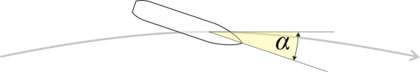
When a ship changes course, it follows a curved path until it is moving in the compass direction the master wants to go. A vessel weighing many thousands of tonnes will need a large centripetal force to hold it on the curve. The sideways thrust of the rudder doesn’t contribute to the centripetal force: in fact it acts in the wrong direction, dragging the stern away from the centre of the curve as shown in figure 12. What provides the centripetal force is the hull itself. The hull can slip easily through the water in the \(x\)-direction (forward) but like a car wheel, it resists skidding sideways in the \(y\)-direction. The lateral resistance is many times higher than the forward resistance because when moving sideways, the hull must push against a much larger quantity of water. It materialises only when the ship’s motion has a sideways component, so the hull must point inwards towards the centre of curve as shown in figure 13 . The angle between the ship’s longitudinal axis and the tangent to the curve has been called the drift angle [14]. Denoted by \(\alpha\), it’s analogous to the slip angle of a car tyre (see Section C1717) or the angle of attack of an aircraft wing. The greater the angle, the greater the lateral force.
Figure 12
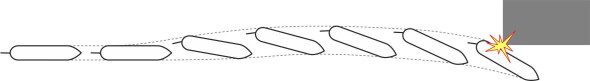
Figure 13
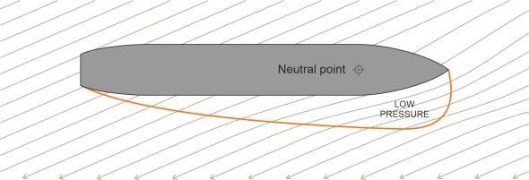
Although it arises from the distribution of water pressure along the ship’s hull, one can picture the force as acting at a single point, sometimes known as the neutral point. You might expect the neutral point to lie somewhere near the middle of the hull, because as shown in figure 14, when a ship is lying stationary in the water and you give it a sideways push, the resistance incurred by the two halves of the hull – front and rear – should be roughly equal. But the picture changes when the ship is moving forward. Typically, the neutral point moves to a position closer to the bow, less than 1/3 of the distance along the hull [13].
Figure 14
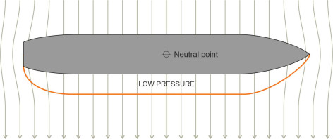
Why should this be? It will help us to focus on the motions of the fluid particles near the bow and near the stern. When the ship is moving sideways with zero velocity in the fore-and-aft direction, we expect a symmetrical flow pattern in plan with roughly equal amounts of fluid spilling round the bow and stern as shown in figure 14, and hence the pressure distribution along the hull will be more-or-less uniform. But if the hull is moving forward at the same time, the pattern changes. As shown in figure 15, an area of low pressure forms on the downstream face of the hull near the bow. This modifies the pressure distribution so that the lateral resistance is concentrated towards the bow rather than at the centre of the hull, in the same way that the centre of lift of an aircraft wing lies close to the leading edge.
Figure 15
Of course, the fluid motion is more complicated than our intuitive model would suggest, for two reasons. First, in a tight turn the angle of attack varies along the length of the hull. As shown in figure 16, at any given moment each part of the hull is moving in a different compass direction, so the concept of a fixed drift angle breaks down. In these circumstances, some analysts prefer to think in terms of a pivot point around which the hull appears to rotate [16] [14] – as figure 16 makes clear, this is the point along the hull whose curved path lies tangential to the ship’s longitudinal axis. Second, the cross-flow of water underneath the bilges creates a vortex in the same way as the air that leaks around an aircraft wingtip (figure 17). The vortex implies a dissipation of energy, meaning that the ship’s resistance to forward motion has increased, echoing the manner in which an aircraft wing creates induced drag. The larger the drift angle, the greater the resistance, so that when a ship turns it will slow down, and in a tight turn with the rudder hard over its speed may fall by as much as a half [3].
Figure 16
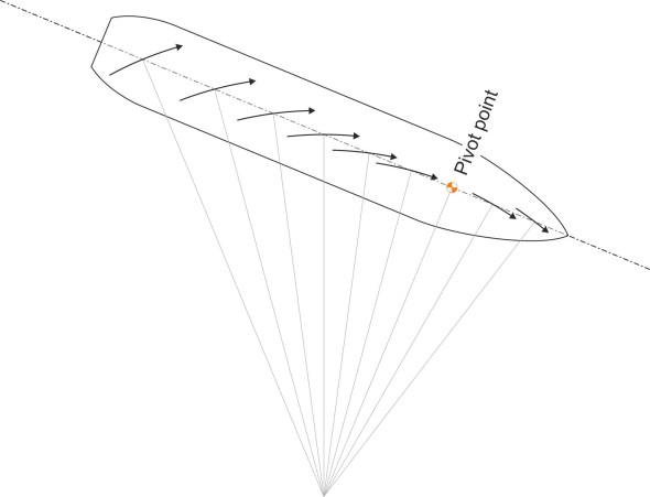
Figure 17
The steering response
On a truck or a railway train, the driver’s cab is located at the front so the driver can see what is happening in the vehicle’s path. But a ship’s steering gear is located at the stern. It’s a long tradition rooted in necessity. Before 1850, the wheel of a sailing ship was placed directly above the rudder to enable a robust mechanical connection between the two. So the helmsman was obliged to stand close to the stern, peering around the masts and maybe posting a lookout to warn of anything in the way. Today, the ‘conning position’ for the master and helmsman of a merchant ship is still located towards the stern. This arrangement is not as awkward as it seems, because a ship changes course in a different way from other vehicles. In a car, when you turn the handwheel to the right, say, the front of the car swings to the right first, and the rest of the chassis follows. But as shown earlier in figure 12, when you turn a ship to starboard, the rear of the hull must first swing in the opposite direction, to port. So if you’re trying to avoid an obstacle such as a jetty or another vessel, your stern will move towards the object you are trying to avoid. This can make manoeuvring at sea more challenging than it is on land, and might explain why a conning position over the rudder has advantages even though the deck and forecastle obscure the view – from there you can keep an eye on what is happening around the stern.
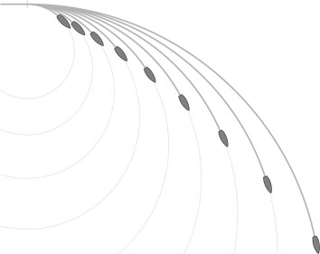
So how can you tell whether a ship is manoeuvrable compared with others of a similar size? A good indicator is the turning circle. If you lay the the rudder over to its maximum angle – say to port – the ship will turn to port along a curve that tightens gradually into a circular path (figure 18). But the diameter of the circle is not a fixed quantity: for reasons we’ll come to shortly it is often a little smaller when turning to port than to starboard, and it also varies according to the ship’s speed. To turn in a small space, the master must slow the ship down and apply full rudder. At high speeds the ship will change course more quickly but it needs more room, because the diameter of the turning circle increases (figure 19). Therefore, in order to test a vessel’s steering ability, one must measure its turning circle separately for each of a range of forward speeds, and we’ll say more about the test procedure in the next Section.
Figure 18
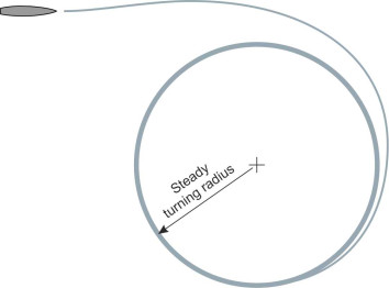
Figure 19
Other things being equal, a small turning circle is desirable so the ship can operate in a confined space when necessary. There are three features to look for. The first is a large rudder. The second is whether the ship has thrusters or azimuth propellers to boost the rate of yaw. The third relates to the shape of the hull itself; some hull shapes will yaw more readily than others. The key dimensions are the length, the draft, and the beam.
The first of these is the most important: manoeuvres have a characteristic time scale that depends on the ship’s length [11]. Suppose two ships A and B are both making a \(90^{\circ}\) turn to port, say. If ship B is twice the length of ship A, it will need twice as much time to complete the turn: as you might have guessed, a short vessel is more agile than a long one. The draft of the hull plays a role too. Suppose that ship B has a shallower draft than ship A. Looking at the ship from the side, a small draft presents less area to the water so that, other things being equal, ship B has less resistance to lateral movement. While it may have poor sea-keeping and be difficult to handle in other respects, ship B can yaw more easily, spinning around its z-axis to change direction in less time than ship A. Hence a traditional river craft such as the coracle, which resembles a shallow bowl almost circular in plan, is highly manoeuvrable but calls for considerable skill to steer.
The effect of the propeller
Among other things, a ship’s propeller squirts a jet of water onto the rudder at high speed, which increases the available steering force whether or not the ship is under way. In this sense, the propeller is almost as important as the rudder for directional control. There is, however, a catch. A propeller doesn’t just push the ship forward, it pushes it sideways too. As explained previously in Section M1410, the wake interacts with the rudder asymmetrically to produce a transverse component, an effect known as the ‘paddlewheel effect’. In fact, a right-handed propeller (rotating clockwise when viewed from astern), will drag the stern to the right, which biases the steering towards the port side [10]. This matters, particularly when two ships find themselves on a collision course. The international convention is that ships normally pass ‘port-to-port’, meaning that each must turn to starboard. With a single propeller running in its normal direction, a ship can’t turn to starboard as sharply as it can to port, but as we shall see in the next Section, the master may be able to exploit the paddlewheel effect by throwing the engines temporarily into reverse.
This procedure only works for single-screw vessels that have a conventional rudder. Some have an asymmetric rudder that balances the lateral forces, and such a vessel gains no advantage from the paddlewheel effect, and nor does a vessel with twin screw propellers, which has no steering bias at all if the propeller shafts rotate in opposite directions. Twin propellers can still assist the steering though. Suppose the master wishes to execute a turn to starboard at low speed in a tight space. The starboard propeller can be disengaged, leaving the port propeller to exert an asymmetric thrust that reinforces the rudder action, and better still, if the port propeller is rotating anticlockwise, the paddlewheel effect will provide an extra boost. The same applies with a turn to port in the opposite sense with the starboard propeller rotating clockwise. This explains why twin propellers are usually geared to turn outwards rather than inwards, with the starboard propeller rotating clockwise and the port propeller rotating anticlockwise [2].
Control in reverse
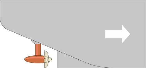
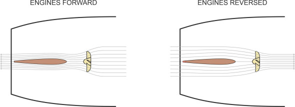
When a driver reverses a car or a truck, the steering works almost as well as it does when going forward. But a ship is different. When going astern, the steering response becomes unpredictable, for two reasons. First, the ship is moving in effect with its rudder at the front, and we’ve already seen that a bow-mounted rudder can’t produce much lateral thrust because the propeller slipstream clings to either side of the hull. Nor would it achieve very much if it could. When a ship yaws, the point around which it pivots – the neutral point – lies close to the bow, and in these circumstances, the rudder has limited leverage. Secondly, the rudder is no longer in the propeller slipstream (figure 20), and the hydrodynamic forces on the rudder blade are correspondingly reduced. In practice, a ship is difficult to control when going astern, and may even turn in the direction opposite to the one intended.
Figure 20
Conclusion
Steering a ship is not a straightforward matter. On the whole, marine craft are less predictable and less easy to control than road vehicles, partly because the steering reponse diminishes when the vessel slows down. In the next Section, we’ll delve a little deeper, asking how one can measure a ship’s manoeuvrability and what factors might influence its performance. Under certain circumstances, it turns out that a ship may not be directionally stable at all.