M.1508
The ship’s hull
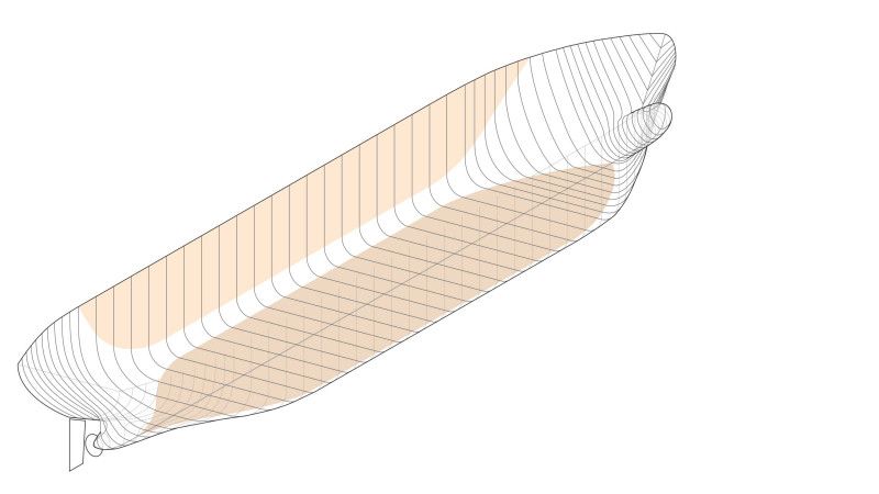
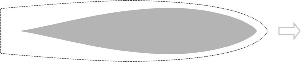
Wherever there is water you will find boats. They range from sailing dinghies scarcely two metres long to oil tankers that measure almost half-a-kilometre from stem to stern. Here, we are interested in the shape of the hull, and although it varies from one vessel to another, the bow is almost always vee-shaped in plan, as if to cut the water like a knife (figure 1). This is not the case with other kinds of vehicle. Submarines have rounded noses not sharp ones, as do passenger jets and high-speed railway trains. Why are ships different? Here, we’ll try to explain some of the distinguishing features of a ship’s hull, specifically those of a displacement vessel whose buoyancy keeps it afloat, as opposed to a planing craft that skates over the surface, which we’ll deal with separately in the next Section.
Figure 1
Hull geometry
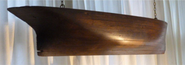
It’s not strictly true that a ship’s bow cuts through the water because the fluid motion is more complicated. Many of the particles displaced to either side have a downward component of motion too, and some pass right underneath the hull. All rise again towards the stern and come together in the ship’s wake (figure 2). It’s a three-dimensional phenomenon, and to understand the pointed bow we’ll need to consider the ship as a whole. A hundred years ago, shipwrights relied on intuition to get the right shape, and built models to help them visualise what was happening. More accurately, they were half–models, and you can still sometimes find them in junk shops (figure 3). Built up from layers of wood and polished to a smooth finish, they brought to light any kinks or bulges that might trigger a disturbance in the water and increase the wave-making resistance, and the dimensions could be scaled up to provide a template for the full-sized version. It wasn’t till the nineteenth century that the principles of hydrodynamics were sufficiently developed to improve hull design on a scientific basis. Among the earliest developments was a set of coefficients that provided a starting point, simple numerical measures that enabled shipwrights to compare the overall proportions of different hull shapes. We’ll look at these first, then go on to consider more detailed aspects of the hull shape in turn.
Figure 2
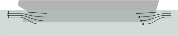
Figure 3
Geometrical coefficients
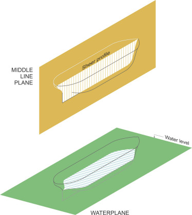
The coefficients are still used today. They are pure numbers, each of which describes some feature of the overall geometry in three-dimensional space. To understand how they work we need a frame of reference. It is determined by two key planes on which the outline of the hull is defined (a) in plan and (b) in side elevation, as previously described in Section M1920. The middle line plane is a vertical plane running along the ship’s axis of symmetry as shown in figure 4. The second reference plane is the design waterplane or load waterplane: it represents the still water surface at right-angles to the middle line plane. Of course, the water level can rise or fall depending on the load that the ship is carrying at the time, so there may be more than one waterplane according to the load condition to which it refers.
Figure 4
This reference frame enables one to determine the most important parameter, the overall hull length. It is not necessarily the same as the length of the waterplane. As explained previously in Section M1920, the marine architect defines two ‘perpendiculars’, the first coinciding with the foremost apex of the design waterplane, and the second with the (vertical) shaft around which the rudder pivots, usually called the rudder post. The hull length is then the horizontal distance between these two perpendiculars.
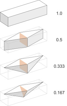
Now we can look at two of the coefficients mentioned earlier. Imagine a rectangular block surrounding the hull of the same overall length (i.e., the ‘length between perpendiculars’). It has the same width of the hull at its widest point, and its depth equals the draft averaged over the length of the hull. Then the block coefficient \(C_B\) is the volume of water displaced by the hull divided by the volume of the block. Over what range might one expect it to vary? The ‘fattest’ ship one imaginable might have a squared-off bow and stern together with a rectangular cross-section, in other words, a rectangular box as shown at the top of figure 5, and the block coefficient would be equal to 1.0. At the other end of the scale, one might imagine a ship having a triangular cross-section with pointed ends as shown at the bottom of Figure 5. Here, the block coefficient is much smaller, just 0.25. Real ships have a block coefficient between these two values. For a large tanker, built to hold as much cargo by volume as possible, the hull swells to fill much of the rectangular box, and the block coefficient might be a little under 0.9. By comparison, a yacht is more slender at the bow and stern, and its block coefficient will be closer to 0.5.
Figure 5
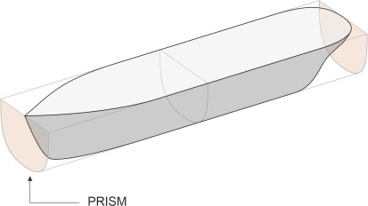
An alternative measure is the prismatic coefficient \(C_P\). This time we imagine the circumscribed body not as a rectangular block, but a prism having the same cross-section as the maximum cross-section of the hull (figure 6). For any given hull, the prismatic coefficient will always be greater than the block coefficient. In different ways, both these coefficients measure the ‘fineness’ of the hull: the extent to which it is tapered at the bow and stern in comparison with one having parallel sides whose ends are simply squared off like a rectangular box. You would expect a low value of either coefficient to signify a hull that will slip easily through the water, but the prismatic coefficient is said to be a better predictor of performance for fast ships.
Figure 6
Entrance and run
This brings us back to the question posed at the beginning: why does the ship need a sharp bow? For boats of almost every shape and size, it’s a tradition that when viewed in plan, the hull makes a sharp vee, or at least is narrow at the point where it first meets the water, to minimise the effect of oncoming waves in a rough sea. Depending on their wavelength, waves carry an appreciable impact when they collide with a ship’s hull, and their impact (a) slows the vessel down, and (b) can cause damage particularly when breaking over the foredeck. Waves arriving on the stern can have a similar impact. Historically, this explains why sailing ships during the nineteenth century were built with a sharp vee both at the bow and the stern, known as a ‘fine entrance and run’. The geometry was usually combined with two other features: sheer and flare. Sheer is a longitudinal raising of the deck at the bow and stern relative to the gunwale amidships, and we’ll return to it in more detail later. Flare has to do with the hull cross-section at the bow: an outward flare as shown in figure 7 means that when the ship dives into the trough between two wave crests, the forepart of the hull displaces more water and has greater buoyancy, and the resulting upthrust holds the bow above the water surface. It first appeared on clipper ships, where the aim was to reduce the tendency for the bow to bury itself into oncoming waves and slow the ship down. Similarly, flare at the stern protects against broaching when a wave arrives from astern. We’ll return to this topic later in Section M1115.
Figure 7
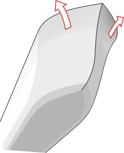
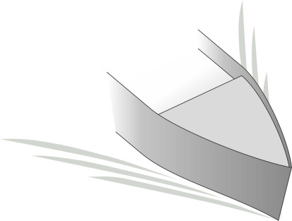
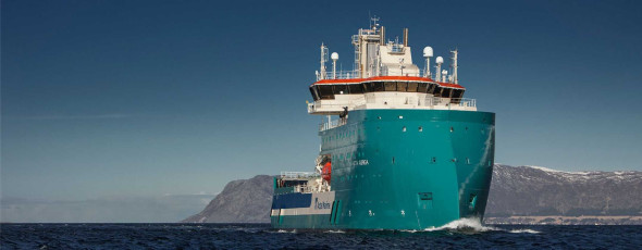
But there are alternatives. In recent years, designers have experimented with configurations such as the ‘axe’, a deep, vertical stem extending below keel level, and also the ‘inverted bow’, in which the superstructure extends like an apron over the foredeck (figure 8). In the latter case, waves that overtop the ship’s waistline simply break against the apron which is angled to soften the impact and there is no possibility of penetrating to the lower decks; the effect is to reduce pitching and slamming forces in heavy seas [14].
Figure 8
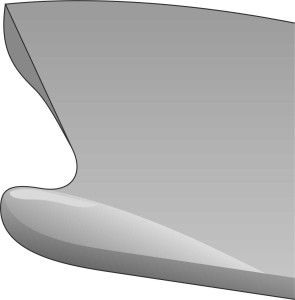
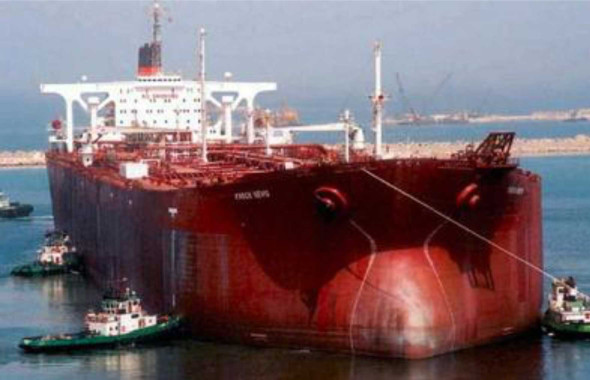
More likely you’re familiar with the bulbous bow, which has been around for a good bit longer and commonly appears on cargo ships today, although its profile varies in shape and size from one vessel to another. A bulge shaped like the nose of a passenger jet, it projects ahead of the hull below the waterline as shown in figure 9, and its profile varies subtly in shape and size from ship to ship. A useful review of the different varieties and their relative merits can be found in [15]. It’s not often that adding a bulge to a vehicle will make it go faster, so how does it work? Depending on the geometry, there are two possible mechanisms at work. First, the bulb effectively makes the hull longer, and as we found out in Section M1620, a longer hull has a lower Froude number, which implies (other things being equal) less wave-making resistance together with a higher ‘hull speed’. Second, the bulb may be profiled so that it acts like an aircraft wing. The curvature of the upper surface causes the water to accelerate and its pressure to fall: this in turn sucks the water surface downwards and reduces the height of the bow wave. Together, these two mechanisms reduce the wave-making resistance for longer displacement vessels that have a high hull speed [1] [11]. However, the advantages of a bulbous bow are not entirely clear cut. The ‘bulb’ lies below the waterline, leaving a short vee section to cleave through the waves at surface level above. In many cases, the vee is less sharp than the bow of a conventional hull, as you’ll see from the illustration of the Seawise Giant in figure 34 at the end of this Section. Research has shown that in rough weather, the blunt stem results in extra drag from the impact of oncoming waves. This doesn’t matter for a very large ship, but the increased surface area implies higher frictional resistance, so the bulbous bow doesn’t work so well at lower speeds [1].
Figure 9
Now it’s time to look briefly at the stern. As you’ll see in Sections F1616 and C1416, the most efficient shape for a vehicle that is totally immersed in a fluid is a ‘teardrop’ shape, which has a pointed tail. Here, the ship obeys the same rules. Although it might appear blunt to an observer on the quayside, traditionally, the stern below the waterline is pointed too - the hull silhouette is in fact pointed at both ends. But on modern cargo ships an equivalent effect is obtained by tapering the stern in a vertical direction: the underside slopes gradually upwards so there is no sudden change of cross-section towards the stern (figure 10). It is often squared off with a flat transom a little above the waterline.
Figure 10
Cross-section
As a child, I naively imagined that if you sliced a passenger ship in two across the middle, you’d find that the bottom was rounded in cross-section. I didn’t know it at the time, but there was some logic in this, because a semi-circular profile has less surface area and therefore weighs less than a rectangular box enclosing the same volume – and therefore, it generates less frictional resistance in contact with the water. In reality, however, this wouldn’t work. As we learned earlier in Section M1818, a semi-circular profile has almost no lateral stability. Like a barrel floating on the water surface, it will roll over at the slightest disturbance.
In reality we find that for most ships, the cross-section below the waterline is quite shallow, more like a flat-bottomed ‘U’ than a cylinder. It’s true that the sides and bilges of a traditional sailing craft are gracefully curved, but the beam is at least twice the draft, so that when it tilts, one half of the hull sinks into the water and displaces more water while the other half rises and displaces less. As a result, the water pressure acting on one half of the hull surface rises, while the pressure acting on the other half falls, thereby restoring the hull to its original position (you’ll find a more precise statement of the conditions required for lateral stability in Section M1818).
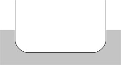
In fact for most large vessels, the hull cross-section is more like a rectangular box than anything else, except that the corners are rounded (figure 11). The near-rectangular form is easier to build than a curved profile because the bottom lies flat on timber baulks laid across the concrete floor of the construction yard. As we’ll see later, it is also better suited to carrying cargo than a curved profile of the same total capacity: the vertical sides and flat bottom mean there is less space wasted around the perimeter of each deck. Finally, it generates less wave-making resistance because it has a narrower beam than, for example, a V-section of the same interior volume, so it creates less disturbance at the water surface [12].
Figure 11
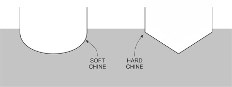
It remains to comment on the curved sections between the bottom and sides. Hulls can be grouped into two categories as shown in figure 12. A ‘soft-chined’ hull has rounded corners inserted between any straight sections in the cross-sectional profile. A ‘hard-chined’ hull consists entirely of straight sections each of which is joined to its neighbour at a sharply defined angle, the ‘chine’. Typically, the bottom is V-shaped. The sharp angles and flat panels encourage planing along the water surface. We’ll return to this kind of hull later in Section M1506.
Figure 12
Sheer, freeboard and buttock lines
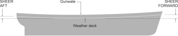
Now let’s view the hull from the side, starting with the outline projected onto the middle line plane. This is known as the sheer profile. The keel of a modern cargo vessel is usually flat, following a horizontal straight line between stem and stern when the ship is sailing in normal trim (a sloping keel would presumably make navigation in docks and shallow waters more risky). Higher up above the waterplane, the geometry gets more complicated. You’ll have noticed that on older ships, the deck is not level, but rises towards the bow and also towards the stern in side elevation. The rise is called sheer, and the sheer forward is usually twice that of sheer aft (figure 13). The raised foredeck protects the bow, reducing the likelihood of it plunging beneath the waves in extreme weather. Note that the term ‘sheer’ relates to deck level, not the sides of the ship as they normally appear in a drawing or picture. The sides are almost always extended above the deck to prevent passengers and crew falling overboard. The extended wall is known as a bulwark, and it is topped by a strengthening member called the gunwale. On many ships the deck is also cambered in cross-section, which enables any water that splashes onto the deck to drain away through the scuppers (holes in the bulwarks).
Figure 13
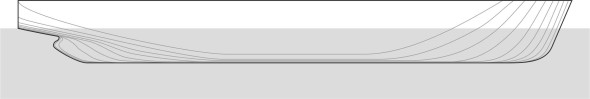
A drawing of a ship viewed from the side is called a sheer plan. It conveys the shape of the hull in three dimensions, by means of contour lines drawn at equal intervals measured outwards from the middle line plane. They are known as buttock lines. For almost any ship you will find that while the stem is nearly vertical, the buttock lines dip down at a shallower angle as shown in figure 14. Towards the stern, they slope upwards again. As mentioned earlier, the aim is to ease the water flow so that the fluid particles are not simply thrust outwards to either side, but downwards too, along a path that involves less acceleration and hence a reduced tendency to turbulence and wave-making. Typically, the bow and stern sections are tapered and the plating is curved in three dimensions, but if the ship is a large one, an appreciable proportion of the hull in between will have a uniform cross-section with flat sides and a flat bottom, as you’ll see from the illustration at the beginning of this Section.
Figure 14
Different kinds of ship
Having introduced some aspects of the hull geometry, we can now try to visualise the ship as a whole. There are of course several kinds of vessel, each having a different characteristic hull shape. Many books have been written on this subject, and it’s not my aim to try and emulate them. Instead, in this Section we’ll focus on just a few kinds of displacement vessel and the way they have developed over time. Our starting point will be the sailing vessel, focusing particularly on its development during the nineteenth century before the arrival of steam.
Traditional sailing vessels
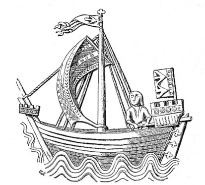
In past centuries, the shipwrights who built wooden sailing boats were inspired by nature, and took as their model the profile of a fish: underneath, the hull surface followed a simple, elegant curve. You wouldn’t think so from the ship’s appearance above the waterline. For example, during the 14th century when the cog was the principal cargo vessel of Western Europe (figure 15), there would be two ungainly structures, one fore and one aft, jutting up from the deck. They were wooden ‘castles’ meant for attack and defence. In the days before cannon became widely available, merchant vessels were often attacked by pirates, who swarmed aboard and engaged the crew in hand-to-hand combat. Height was the key. From a tall platform, they could grab a rope, swing aboard, and overwhelm the defending crew. Likewise, the defending crew stood a better chance of survival if they were stationed at least on the same level as their assailants. The result was an early form of ‘arms race’ with higher and higher deck levels fore and aft. This may explain why the captain’s quarters on the 19th century fighting ships of Nelson’s day were located high up at the stern. Even today, the raised foredeck of a ship is called the ‘forecastle’ or fo’c’sle for short. The stern deck – if there is one – is called the poop.
Figure 15
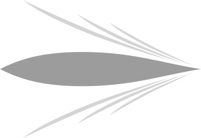
Beneath the waterline, it was a different story. From the 14th century onwards, the hull was streamlined with a rounded nose and long, tapered tail like a mackerel fish [2] [9] (figure 16). The rounded nose was intended to protect the vessel against heavy seas: it conferred extra buoyancy so the bow would rise over an oncoming wave rather than dive under the crest. The rounded nose continued with minor variations until midway through the nineteenth century, when shipwrights began to search for hull shapes that offered less resistance.
Figure 16
On one point at least, most were agreed: to achieve a high cruising speed, the hull of a traditional sailing vessel should be long and thin [4]. The bow had a fine entrance, meaning a sharp ‘vee’ to part the water cleanly. The sides of the hull curved thereafter towards its widest point a little way ahead of the half-way mark, then the planks straightened out to form a longer ‘vee’ towards the stern. This was called a fine run. However, there were different schools of thought that led to subtle variations in the design, each claimed to produce better results than those of their rivals. For example, it became fashionable for a while to hollow out the entrance and run with a reverse curve as shown in figure 17 [6].
Figure 17
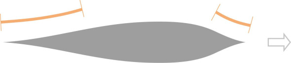
But evidence was sparse. Even today, it is not easy to measure the behaviour of a sailing vessel in objective term, for two reasons. First, conditions change rapidly at sea: the direction of the wind and the set of the sails both vary from moment to moment, and with them, the angle of the hull and its cross-sectional shape as presented to the water (figure 18). For both these reasons, the resistance is constantly changing with the strength and direction of the wind, which makes it difficult to compare different vessels under the same conditions.
Figure 18
So, during the nineteenth century, sailing vessel design was essentially ‘a mystery and an art’. Nevertheless, performance improved with successive generations, culminating in the magnificent ‘clipper ships’ that raced to bring seasonal cargo from the Far East to Europe. In reality, the gains had little to do with the shape of the hull – they were mostly attributable to its length [7]. In fact, many of the vessels that made record-breaking voyages during the heyday of exploration did so because they could maintain a modest but consistent speed from day to day in variable weather.
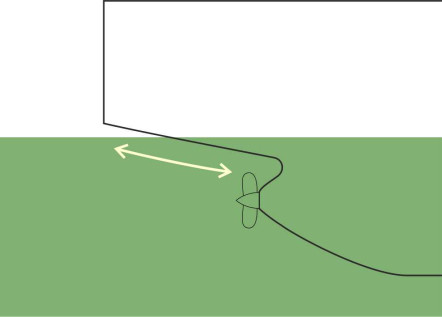
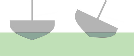
A sailing ship heels at an angle when the wind is on the beam (blowing from either side), and this raises problems that continue to challenge the designers of leisure craft today. To stop it from capsizing, a yacht needs a counterweight or ballast placed at the bottom of the hull, and in fact, early European sailing ships were loaded with stones in the bilges on either side of the keel [17]. Moreover, the hull doesn’t actually move in the direction is seems to be pointing, or at least not precisely so, because the wind tends to drive it sideways at an angle to its intended course. The sideways component of velocity is referred to as leeway, and it disturbs the flow of water around the hull. This is why most sailing ships have a V-shaped keel, which keeps the direction of motion within \(10^{\circ}\) leeward of the steered course [3]. On recreational sailing craft, the effect is enhanced by a ‘fin’ keel that projects below the envelope of the hull (figure 19). If a yacht needs ballast, the bottom of the fin is a good place to put it because it maximises the righting moment per kilogram of material.
Figure 19
The motor ship
Today, the marine architect is in a better position. It’s possible to assess a vessel’s likely performance before it leaves the drawing board, because unlike a sailing ship, a modern motor vessel stays mostly upright and travels at a steady cruising speed. With the aid of model tanks and computer simulation one can test the effect of varying the hull shape and size, and optimise the geometry taking into account the conditions under which it is likely to operate.
A key consideration is the cruising speed. As explained in Section M1619, for a slow vessel, friction dominates, so to minimise drag (and therefore, to minimise fuel consumption), we need a hull with minimum surface area, in other words short and fat, maybe with a shallow, rounded bilge in cross-section. What about faster vessels? Here, the wave-making resistance dominates, and other things being equal, the longer and narrower the hull, the less the wave-making drag and the better the fuel economy. But there are other considerations. If you are designing a vessel for a particular task, it’s not just a question of speed. There is also cargo-carrying capacity, manoeuvrability, and sea-keeping (particularly stability in roll). So let’s consider three types of displacement vessel and try to explain the distinguishing features of the hull in each case, beginning with cargo vessels.
Cargo vessels
One imagines a ship’s hull as following a smooth and streamlined envelope below the water surface. But curved shapes are less important for cargo vessels. Nowadays, they are much larger and longer than they used to be, and because their increased length implies less resistance per tonne than their predecessors, ‘fine lines’ confer less of an advantage. And there is a drawback to a slender hull that we hinted at briefly in Section M1619. The greater the length, the greater the bending stresses that can arise in heavy seas when the ship bridges over the trough between two wave crests, or hogs over a single peak. To cope with these stresses, the plating and supporting members have to be strengthened, which means more weight and less cargo-carrying capacity. Most merchant ships today have a length-to-beam ratio typically around 6:1 or 7:1, with a convex entrance and run and long, straight sides in between as shown in figure 20. A straight-sided hull is relatively cheap to build and it can be extended during its liftime by inserting a new section amidships. The predominant requirement is capacity, so large ships tend to be rectangular in cross-section to hold the maximum cargo (see figure 21). For ships designed to pass through the Panama Canal, the beam is limited to 55 m. This is in stark contrast to warships during the last century, which were curved in plan, with the beam widest amidships to provide a stable gun platform, coupled with a long and sharply pointed bow and stern (figure 22).
Figure 20
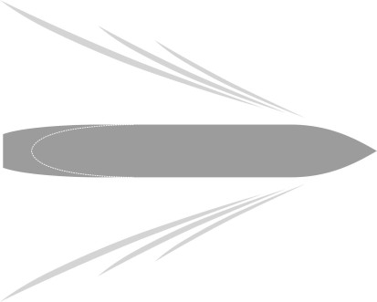
Figure 21
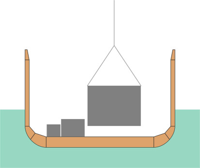
Figure 22
Passenger vessels
The requirements for a passenger vessel are different, and they vary according to the market they serve. A cruise ship is designed to carry people in comfort, perhaps as many as 2 000 passengers plus 1 staff for every 2 passengers. The passengers expect space, quietness, and freedom from vibration, which implies many decks above water level - some cruise vessels are 14 or more stories high, and the superstructure is constructed from lightweight materials such as aluminium to keep the centre of mass low down, close to the water surface. Since no-one is going anywhere in particular, the cruising speed is not as important as it once was for the passenger liners that raced across the Atlantic during the first half of the twentieth century: a little over 20 kt is sufficient [8]. More important is good stability and seakeeping. The hull profiles are not very different in cross-section from cargo ships, although the proportions may vary. Some roll slowly and easily, which may be a good thing in rough weather. Conversely, a vessel that is ‘stiff’ in roll will oscillate at a relatively high frequency in time with the waves. Other things being equal, a high frequency implies high accelerations, which (as we’ll see later in Section M1115) can be uncomfortable for passengers and crew. Many boats have stabilising devices that reduce roll, especially passenger vessels where comfort is a priority. The simplest such device is the bilge keel. Found on many smaller vessels, the bilge keel has been in existence since the early nineteenth century. Originally conceived by William Froude, it is an elongated fin attached lengthways to the hull surface as shown in figure 23. It has the effect of damping the tendency to roll in rough weather. A more sophisticated alternative is the stabilising plane - a moveable fin whose angle relative to the oncoming water is continually adjusted under automatic gyrosopic control to resist the rolling motion of the hull. It only works when the ship is moving.
Figure 23
Ferries are a different matter. The aim is to get from A to B as quickly as possible and execute a quick turn-around to minimise the time spent wasted in port, which may involve manoeuvring in a confined space under the vessel’s own power. Many are designed to carry vehicles as well as passengers, in which case they follow a two-tier layout with vehicles on a lower deck with passengers accommodation above. As related earlier in Section M1818, a vehicle deck covers a large, uninterrupted area, which can pose a severe problem if the entry doors work loose or are accidentally left open. Ferries often operate at high speed in shallow water where there is a risk of grounding, and as we’ll see in the next Section, new hull forms have evolved to meet the challenge.
Structure
When you board a ferry or set out on a holiday cruise, you don’t worry about the strength of the hull: the ship is unlikely to break up in mid-voyage. In fact, a great deal of effort goes into the design and construction of each vessel so it will stand up to rough conditions at sea. The art and science of ship construction falls within a distinct branch of engineering called marine architecture. We won’t go into detail here (there are many good textbooks on the subject, for example [10]), but rather, we’ll try to draw out certain aspects in non-technical terms.
The flimsy bowl
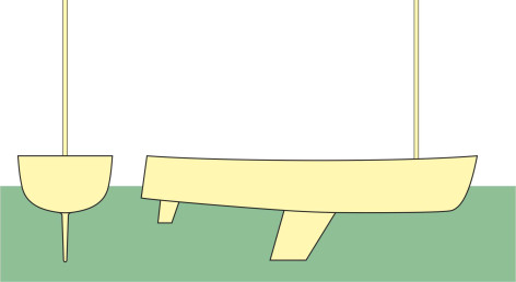
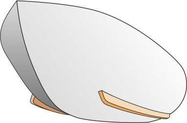
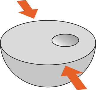
Essentially the hull is an elongated bowl, which is not a very rigid structure. The weakest part is the rim. Without any bracing, it has little resistance to deformation, and you can imagine how easily the sides will distort if squeezed inwards under the action of a freak wave (figure 24). That’s why small boats need reinforcement around the gunwale to keep their shape. In theory, a better solution is to turn the bowl into a closed box, whose top is firmly bonded to the rim around its circumference. The top transforms a somewhat floppy structure into one that is relatively strong and rigid: you can even cut a hole in the top (not too large) and the sides will withstand considerable force without losing their shape. Now scale the bowl up in size, and you will have created a boat you can sit in, something like a kayak (figure 25).
Figure 24
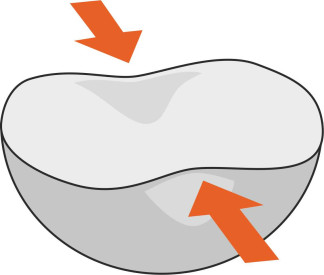
Figure 25
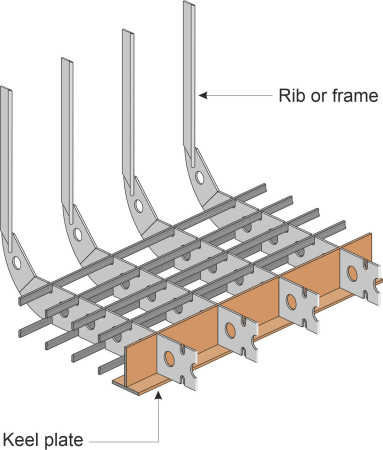
The same idea applies to larger vessels: the main deck, usually called the weather deck, spans between the bulwarks and transform what would otherwise be a weak structure into a box that keeps its overall shape. But in practice the hull must still be reinforced so it resists being dented locally under the impact of a wave crest or a loose item of cargo. The reinforcement is traditionally provided by ribs, fixed transversely to the keel, and there may be longitudinal stiffeners too. Likewise, the deck is supported on cross-beams. Not only do they reinforce the hull, but the ribs, stiffeners and crossbeams provide a framework that defines the shape of the hull during the construction process. An example showing the framework for a modern steel cargo vessel appears in figure 26. Construction begins with the keel laid on the ground – the ribs are then attached to the keel, and the stiffeners and cross-beams follow. Finally, the plating is welded to the frame together with transverse bulkheads that further reinforce the structure and increase its stiffness especially in torsion.
Figure 26
Clinker and carvel
Ribs were first introduced for wooden boats in prehistoric times, and the Greeks and Romans developed the technique when building their galley ships. The outer skin was made from wooden planks fixed to the ribs to make a smooth surface. Today this construction is called carvel construction (figure 27) and it is still occasionally used for larger wooden vessels today. But there is a problem: any movement of the planks relative to one another will allow water to leak into the ship, so the joints must be caulked with a sealant. The gaps between the planks are tapered in cross-section. The traditional sealant, made from cotton and hemp fibres soaked in tar, is driven into the gaps from the outside of the hull with a mallet and specially shaped chisel, and covered over with putty. The process works well but the caulk must be renewed at regular intervals. In Greek and Roman times, there was no comparable sealing process and the boats tended to leak when the hull flexed in a heavy sea.
Figure 27
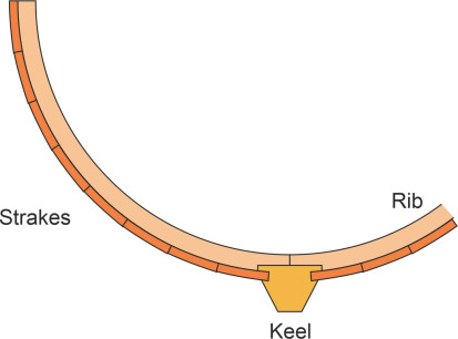
Wooden construction improved markedly with the arrival of the Viking longboat. The difference lay in the way the planks were fixed. The edges overlapped in a distinctive fashion, with each pair of adjoining planks fixed to one other by clench nails or copper rivets driven through both planks and into the supporting frame. This greatly reduced any tendency for joints to work open; nowadays a vessel built in this way is said to be clinker-built (figure 28). It’s almost watertight, and because it is a relatively robust structure the planks can be thinner so that overall, the hull is lighter than a carvel-built hull of the same size. This in turn means it can carry a greater load. On the other hand, each plank or strake is a single piece of wood running along the whole length of the vessel, which restricts the clinker method of construction to relatively small craft. This is because butt joints are weak and tend to pull apart under tensile loads.
Figure 28
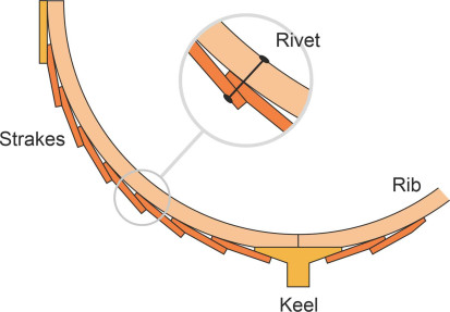
Also, compared with a carvel hull, a clinker-built hull is far from smooth. The overlap between neighbouring strakes means that the outer surface has a jagged profile in cross-section. Any rough surface will disturb the fluid boundary layer and generate extra resistance. In principle, a shipwright can minimise the disturbance by aligning the strakes with the fluid flow so the particles don’t turn any sharp corners on their way from stem to stern, and indeed, if you look at a dinghy or a fishing boat drawn up on the beach, the lines of the strakes map out what you might imagine to be the streamlines in the fluid boundary layer as it slides underneath the hull. However, in reality we know little about the fluid motion under a ship’s hull when it puts to sea. The paths followed by the fluid particles are neither smooth nor steady over time, because (a) the flow is turbulent, and (b) the hull pitches and rolls with each passing wave, so the direction of flow varies from moment to moment, especially in rough weather. Hence it appears that even the most carefully designed clinker hull presents a rough surface to the water and generates more resistance than a carvel hull of the same size and shape, but I haven’t yet found any experimental evidence to confirm this.
Having passed their heyday during late nineteenth century, wooden ships nowadays are comparatively rare. There is a limit to the size of hull you can build using traditional materials, because a wooden ship isn’t sufficiently rigid – it flexes in heavy waves. A small boat is fine because when it meets a wave, it rides up the oncoming face, passes over the crest, and rides down the other side (figure 29). Although the occupants may get wet, the hull will survive intact. But a larger boat encounters a problem: it must bridge across the peaks. The weight of the boat causes it to sag in the middle, bending like a beam that bridges horizontally between two supports with a load applied vertically in the centre as shown figure 30. The beam will bend downwards in the middle, which squeezes the upper surface and stretches the underside of the beam, to produce compressive and tensile stresses whose intensity varies across the depth of the beam.
Figure 29
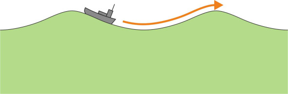
Figure 30
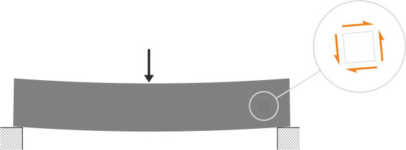
But as we shall now see, the greatest threat to a wooden boat arises from the shear stresses that accompany the compressive and tensile stresses during the bending process. The dotted square in figure 30 represents a small element of the beam, and the orange arrows indicate the shear stresses acting it. So how do they arise? Let’s carry out a thought experiment. Suppose we slice the beam into horizontal layers as shown in figure 31, doing it quickly while the beam is still under load. This greatly weakens the material because it severs the connections between the different layers that otherwise act together to give the beam its rigidity: now that they are acting individually, they have little resistance to bending, and if the layers are slippery like playing cards they will slide over one another as they bend. The beam will sag further as shown in the lower half of the Figure: all the cards deflect in the middle by the same amount, sharing the load more-or-less equally among them. The direction of sliding indicates the direction of the shear forces between the individual layers before the cuts were made.
Figure 31
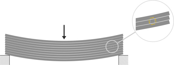
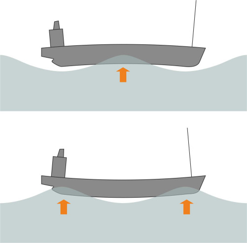
For a wooden boat the shearing action is a serious issue. Let’s return to our ship battling through a rough sea. It’s an old-fashioned ship with wooden planking. The hull sags when it bridges between consecutive waves, and since the strakes are more like playing cards than a solid beam, they slide a little relative to one another so that the vessel flexes more than the equivalent solid structure (figure 32). And as shown in figure 33, when a wave crest reaches the middle of the boat, the hull will ‘hog’ over the top. These two conditions, sagging and hogging, mean that the shear stresses in the hull material undergo a reversal with each wave. Repeated stress reversals will cause a wooden boat to leak and lose structural integrity, so it is vulnerable if it runs aground. This effectively limits the length of a traditional wooden hull to about 50 metres or 150 feet. During the 19th century, shipwrights who were anxious to build larger vessels tried to stiffen the hull by various means [5], but the solution ultimately was to replace the planks with a sheet material that resisted shear.
Figure 32
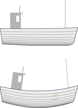
Figure 33
Iron and steel
It was iron that changed the shipbuilding industry. Although expensive, iron plates could be riveted together to make a continuous, strong and watertight hull. You might suppose that an iron hull would be heavier than the equivalent wooden one but in fact the reverse was true. Wood has planes of weakness so the frame of a wooden ship needed thick-set ribs and planks to ensure it didn’t split or pull apart. A much smaller quantity of iron could do the same job, with the result that an iron hull was cheaper, lighter and consumed less fuel. It was also more dependable, being less likely to break up under stress. Transverse bulkheads – panels stretching across the width of the vessel – added greatly to the hull stiffness and strength, and also performed a valuable safety function by dividing the ship into a series of watertight compartments that improved the chances of survival if the ship ran aground. Also it was possible to add longitudinal bulkheads that prevented liquid cargo from sloshing from side to side and capsizing the ship in a heavy sea.
Eventually, shipwrights turned to mild steel, which made the hull lighter still [16], and soon it was being used in every shipyard. The weight reduction enabled a vessel of any given size to carry up to 10% more cargo, and made possible for the first time a cellular double bottom [16], a feature that greatly improved maritime safety. Over time, steel construction became significantly cheaper with the introduction of welding, meaning that a steel skin could easily be attached both to the inside and to the outside of a framework like the one shown earlier in figure 26. Although steel was more liable to corrode than iron, the development of cathodic protection slowed the process down [13] and enabled a further reduction in plate thickness and weight, which was fine as long as the material retained its toughness and strength over long periods at sea. But this wasn’t always the case. Later in Section M1115 we’ll see that ships began to break apart in mid-voyage for reasons that no-one had foreseen at the time.
Conclusion
Until the Industrial Revolution, shipbuilders worked with natural materials that they could find nearby. There were few books on naval architecture, so they learned from experience and handed down their knowledge to the next generation with occasional improvements and innovations that were based on intuition, or copied from ships visiting the country from overseas, and occasionally from ships captured in war. Even today, shipbuilding remains an art as well as a science. Cargo ships dominate the oceans, and while they are big, heavy, and slow, their designers use sophisticated methods to maximise capacity and performance. By contrast, smaller vessels such as passenger ferries are getting faster. They need a quick turn-round time and often take on a very different hull shape. One of the most exciting aspects of marine technology is the development of new forms, some exotic and even outlandish, looking nothing like a ‘ship’ as it would have been understood only a generation ago. These will form the topic of the next Section.
Figure 34
Acknowledgements
Figure 01 Ship’s hull: Drawing by the author
Figure 08: the Acta Auriga with its ‘X-bow’ hull on sea trial in March 2018, by kind permission of the builders Ulstein Group ASA and owners Acta Marine.
Figure 15 Medieval cog: Herrick, Public domain via Wikimedia Commons, available at https://commons.wikimedia.org/w/index.php?curid=2602411 (accessed 16 Oct 2016).
Figure 34: TT Knock Nevis, formerly Seawise Giant, image at https://en.wikipedia.org/wiki/Seawise_Giant#/media/File:Knock_Nevis.jpg (source http://supertankers.topcities.com/id132.html, copyright: Auke Visser’s International Super Tankers, accessed 13 May 2021).