M.1818
Floating upright
It’s one thing to build a ship that will float, and another to make it float the right way up. If the hull is the wrong shape, or the cargo breaks loose, it may roll over and capsize. Many ships have been lost in this way. One of the most famous was the Vasa, the flagship of the Swedish Navy. On 10 August 1628, it heeled over in a strong breeze after sailing a little over a kilometre on its maiden voyage out of Stockholm [4]. Water poured in through the gun portals, the ship sank, and many of the crew drowned. It wasn’t altogether the shipwright’s fault. The Vasa was carrying more guns on the top deck than he had allowed for, and they made the vessel unstable. This can happpen to any vehicle: a stagecoach, for example, is liable to tip over if it is carrying heavy luggage on the roof. But the conditions that determine whether a ship will capsize are more subtle, because its stability depends not only on the weight distribution but also on the mass of water that a hull displaces, which changes shape when the vessel heels to one side. In what follows, we’ll describe a diagnostic tool that predicts whether a ship will be stable in calm water, and points towards a better hull shape if it’s not. In later sections we’ll go on to consider the ship’s handling in stormy weather.
Hydrostatic stability
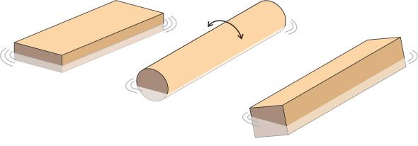
Children love to play with things in water, for example, wooden bricks floating in the kitchen sink. It’s interesting to see what happens when you drop them in, because they don’t always do what you’d expect. Figure 1 shows three bricks, each with a different cross-section. A flat block will float horizontally like a lily leaf and will resist strongly if you try to tip it over, while a circular cylinder has no preferred orientation: it will spin freely around its longitudinal axis when disturbed. But in other cases, the outome is less easy to predict. The third brick has a square cross-section, and it’s floating at an angle to the water surface – not a good model for a cruise liner or a cargo ship.
Figure 1
Rectangular blocks
Since most ships nowadays have a cross-section that is broadly rectangular in shape, let’s focus on rectangular blocks. We’ll vary their proportions and imagine they’re made from diverse materials such as wood or expanded polystyrene foam so their densities will vary too. What happens when we put them in a bowl of water? Suppose the first block is shaped like a paperback book. Its length \(L\) is greater than the breadth \(B\), which in turn is greater than its thickness \(H\). Which way up will it float? You would guess it comes to rest with one of the larger faces (the front or rear cover of the book) uppermost. Like the flat slab mentioned in the last paragraph, it floats parallel to the water surface (figure 2). It doesn’t matter whether the block is made of a light, low-density material or a heavy one. If it’s a low-density material it will float with most of the block projecting above the surface. A block made of denser material will float like an iceberg, with most of the block below the surface and only a small portion visible above.
Figure 2
But what would happen if we turned it through ninety degrees? If it were heavy enough, it might float ‘on edge’ with most of its volume submerged, but it’s not obvious whether it would stay upright for long. Regardless of how you handle them, some rectangular blocks will rotate and come to rest with none of their faces horizontal. To predict the outcome, we’ll need to analyse the forces involved, and hopefully this will lead to a diagnostic tool for predicting the stability of a ship’s hull.
The metacentre
A ship’s hull presents a greater challenge, because (a) the geometry at the stem and stern is more complicated than that of a rectangular block, and (b) its centre of gravity G can in principle lie anywhere within the volume enclosed by the hull - the designer can move G around, for example by re-locating heavy items such as the engines low down, close to the keel. There is another factor to be taken into account, because when a ship heels to one side, the buoyancy force moves as well. Its position is tied to the body of the water that the hull displaces, which changes shape whenever the hull rotates away from its normal alignment. Hence the ship’s ability to resist a capsize depends not only on the weight distribution but also on geometry of the hull cross-section.
Figure 3
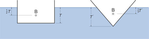
To see how, we’ll first need to fix its position when the ship is floating upright. It simplifies matters to assume that the ship is symmetrical about the vertical plane that passes longitudinally through the bow and the rudder post as shown in figure 3 – the so-called middle line plane. For a rectangular block sitting upright in still water, the centre of buoyancy lies in the middle line plane halfway between the waterplane and the underside of the block at a depth of \(T/2\), while for a hull of triangular cross-section it is higher up, at a depth of \(T/3\) (figure 4), where \(T\) is the draft. For ship hulls of a more realistic shape it lies somewhere between.
Figure 4
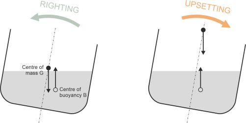
When a ship heels to one side, say starboard, the right-hand semi-hull descends and displaces more water while the left-hand semi-hull rises and displaces less. Hence the centre of buoyancy moves to starboard (figure 5), and the line of the upthrust moves with it. And of course the centre of mass moves as well, so the key to the problem lies in the relationship between the two. If the centre of buoyancy B moves further than the centre of mass G, the two forces together will produce a ‘righting couple’ that tends to roll the ship back upright again. If it doesn’t and B remains to the left of G, they will produce an ‘upsetting couple’ and the heel will increase (figure 6).
Figure 5
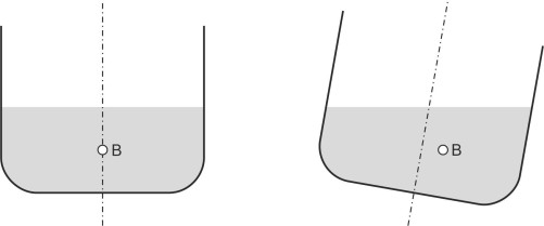
Figure 6
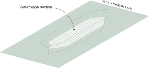
It seems that the relationship between B and G determines the ship’s transverse stability in calm water, but it can be expressed in a neater form. What matters is not the location of the point B as such, but the line of action of the buoyancy force that passes through it. As shown in figure 7, this line cuts the ship’s middle line plane at a point M some distance above. The position of M will vary a little according to the angle of heel \(\phi\), but as \(\phi\) tends to zero, it converges on a fixed point of reference known as the metacentre. We can work out the position of the metacentre if we know the values of three key parameters that characterise the shape of the hull. They are (a) the volume displacement below the water surface, (b) the waterplane section (the striped area shown in figure 8, and (c) the centre of buoyancy B. These three features alone determine the location of the metacentre in relation to the hull cross-section of the hull. Surprisingly perhaps, the detailed geometry of the cross-section is irrelevant – it makes no difference whether its surface profile is smoothly curved, or jagged, or shaped like a rectangular box.
Figure 7
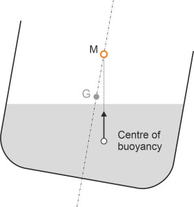
Figure 8
The idea of using the metacentre to gauge the stability of a ship in roll was originally conceived by the French mathematician Pierre Bouguer (1698-1758), who is widely regarded as one of the founders of modern naval architecture. Once the position M of the metacentre is known, together with the position G of the centre of gravity, Bouguer’s method boils down to a straightforward comparison between the two. The distance of M above G is known as the metacentric height. If the metacentric height is positive (M is higher than G), you can see from figure 7 that the upthrust provides a righting moment so that after a small disturbance the ship will return to an upright position: it is stable in calm water at least for small angles of heel. On the other hand, if the metacentric height is negative (M lies below G), when disturbed, the weight of the ship and its cargo together with the upthrust will form an overturning couple and the vessel will tend to capsize. In practice, a marine architect will repeat the calculation for a variety of loading conditions, and set out the results in a standard format [10].
Deriving the metacentric height
It remains to determine a formula for the metacentric height. Although the maths is cumbersome, the solution emerges in the form of a beautifully simple equation. We start with the silhouette of the displaced body of water viewed from above: on other words, the waterplane section shown in figure 8. Its outline can be described mathematically as a closed curve whose offset \(Y\) from the central axis varies along the length of the hull. Let’s denote distance in the longitudinal direction by \(X\). Then strictly speaking, \(Y\) is a function of \(X\), so we should write the offset at any particular longitudinal distance \(X\) as \(Y \left( X \right)\), but we’ll just call it \(Y\) for simplicity. The geometry is shown in figure 9. From this curve we estimate the second moment of area \(I_{\text{area}}\) of the waterplane section. If you haven’t come across it before, this quantity arises in other branches of science and engineering, for example in structural analysis, where it is used to work out the stress pattern within the cross-section of a beam in bending: we met it earlier in Section R1412 in connection with the stiffness of a steel rail. The procedure is as follows.
Figure 9
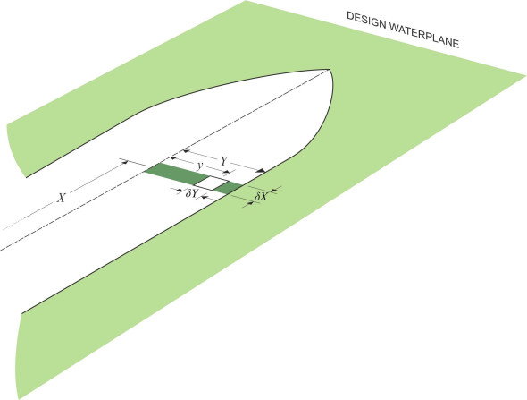
First we divide the waterplane section into transverse strips. One such strip is highlighted in figure 9; its width is \(\delta X\). Consider a small rectangle within this strip of length \(\delta y\). We multiply its area \(\delta A\) by the square of its distance \(y\) from the middle line plane, which gives us the product \(y^{2} \delta y \delta X\), then repeat the process for all rectangles within the strip, and add the results together to get a quantity we’ll call \(\delta I\):
(1)
\[\begin{eqnarray} \delta I \quad & = & \sum y^{2} \delta A \nonumber \\ & = & 2 \int_0^{Y} y^{2} dy . \delta X \nonumber \\ & = & \frac{2}{3} Y^{3} . \delta X \end{eqnarray}\]If we do the same for all the strips that make up the length \(L_{WL}\) of the waterplane section and sum the results, we arrive at the second moment of area \(I_{\text{area}}\):
(2)
\[\begin{equation} I_{\text{area}} \quad = \quad \sum \delta I \quad = \frac{2}{3} \int_0^{L_{WL}} Y^{3} dX \end{equation}\]Why is this quantity important? The answer is that it determines the restoring force that returns the hull to an upright position after a disturbance. Suppose that the ship heels a small angle \(\delta \phi\) to starboard. The starboard half of the hull will displace an extra wedge-shaped body of water. Let’s examine a transverse slice of the hull of thickness \(\delta X\). Within this slice the volume of the wedge is indicated in cross-section by the green triangle in figure 10.
Figure 10
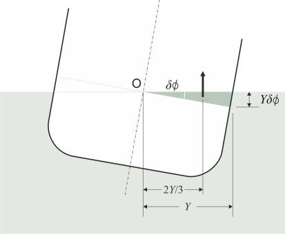
The area of the triangle is \(\frac{1}{2} \times \text{base} \times \text{height} \; = \; \frac{1}{2} \times Y \times Y \delta \phi \; = \; \frac{1}{2} Y^{2} \delta \phi\), and the volume of the displaced water \(\frac{1}{2} Y^{2} \delta X.\delta \phi\). It produces an upthrust equal to \(\rho g\) times the volume of the element or \(\frac{1}{2} \rho g Y^{2} \delta X.\delta \phi\). The upthrust effectively acts at the centroid of the green triangle, two-thirds of the way along the waterplane, so the lever arm about O is \(\frac{2}{3} Y \delta \phi\) as shown in figure 10. Hence the upthrust exerts a restoring couple \(\delta R\) in the anticlockwise direction about the point O given by
(3)
\[\begin{eqnarray} \delta R \quad & = & \quad \text{upthrust}\ \times \ \text{lever arm} \nonumber \\ & = & \quad \left( \frac{1}{2}\rho g Y^{2} \delta X.\delta \phi \right)\ \times \ \left( \frac{2}{3} Y \right) \nonumber \\ & = & \quad \frac{1}{3}\rho g{{Y}^{3}}\delta X.\delta \phi \end{eqnarray}\]Now we can sum all the slices that are stacked along the length of the hull to get the overall wedge restoring couple \(R_{\text{starboard}}\) associated with the wedge of water displaced on the starboard side. We find
(4)
\[\begin{equation} R_{\text{starboard}} \quad = \quad \frac{1}{3} \rho g \delta \phi \int\limits_{0}^{L} Y^{3} dX \end{equation}\]In addition the port side of the hull rises, so there is a loss of buoyancy that produces another restoring couple \(R_{\text{port}}\) in the same direction (anticlockwise) and equal in value to \(R_\text{starboard}\). So the overall ‘wedge restoring couple’ \(R\) associated with the change in water level on either side of the hull relative to the original waterplane section is given by
(5)
\[\begin{equation} R \quad = \quad R_{\text{port}}\ +\ R_{\text{starboard}} \quad = \quad \frac{2}{3} \rho g \delta \phi \ \int\limits_{0}^{L} Y^{3} dX \end{equation}\]which can be written
(6)
\[\begin{equation} R \quad = \quad \rho g \delta \phi \ \left[ \frac{2}{3} \int\limits_{0}^{L}Y^{3} dX \right] \quad = \quad \rho g I_{\text{area}} \delta \phi \end{equation}\]Figure 11
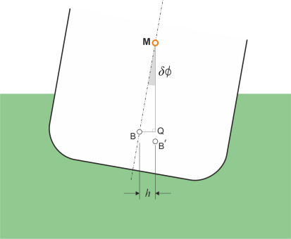
Now we can begin to understand the role played by the second moment of area \(I_{\text{area}}\). The wedge restoring couple shifts the centre of buoyancy through a horizontal distance \(h\) to a new location B\('\) as shown figure 11. The vertical line through B\('\) intersects the centreline of the hull at M. If we take moments about the original position B of the centre of buoyancy we see that the buoyancy force times the distance \(h\) must be equal to the wedge restoring couple. It follows that the distance \(h\) is given by
(7)
\[\begin{equation} h \quad = \quad \frac{\text{Wedge restoring couple}}{\text{Buoyancy force}}\quad = \quad \frac{ \rho g I_{\text{area}} \delta \phi }{ \rho g \nabla }\quad = \quad \frac{I_{\text{area}}}{\nabla }\delta \phi \end{equation}\]and since in the triangle MBQ the base \(h\) is asymptotically equal to \(\overline{\text{MB}} \times \delta \phi\), there follows a simple and elegant result:
(8)
\[\begin{equation} \overline{\text{MB}} \quad = \quad \lim_{ \delta \phi \to 0 } \left( \frac{h}{\delta \phi } \right) \quad = \quad \frac{I_{\text{area}}}{\nabla } \end{equation}\]The above derivation is not rigorous: it relies on a series of geometrical approximations that assume small angles \(\delta \phi\) of heel. But as \(\delta \phi\) approaches zero, the position of M converges on a fixed point that lies a distance \(I_{\text{area}} / {\nabla }\) above the centre of buoyancy, and this is the metacentre that we seek.
Figure 12
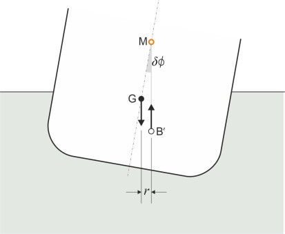
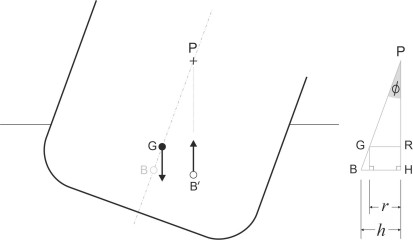
We can now forget about the wedges and picture the ship’s buoyancy as a single force acting upwards in its new position B\('\). It no longer acts in the same vertical line as the ship’s mass, so the two forces together produce an overall couple. Referring to figure 12, we see that if the metacentre M lies above the centre of gravity G, this couple acts to restore the ship to an upright position, and the greater the horizontal separation \(r\) between the two, the greater the restoring couple. The distance from M to G is known as the metacentric height. We shall measure it as positive downwards and denote its value by \(\overline{\text{MG}}\). The distance \(r\) is referred to as the righting lever. Its value is given by
(9)
\[\begin{equation} r \quad = \quad \overline{\text{MG}}\ \times \ \delta \phi \end{equation}\]so the higher the metacentre above G, the more powerful the righting action. On the other hand if M lies below G, the distance \(\overline{\text{MG}}\) becomes negative, the righting couple becomes an upsetting (clockwise) couple, and any disturbance will cause the angle of heel to increase.
Hull configurations
In the 17th century, a sailing ship was usually ballasted with weights in the bottom of the hull on either side of the keel; acting like a pendulum, they lowered the centre of gravity and helped to keep the vessel upright in a strong wind [3]. In much the same way, the weight distribution inside a modern submarine is designed to keep the centre of gravity below the centre of buoyancy, otherwise, it will roll over as soon as it submerges [14]. But for most ships today, the centre of gravity is actually above the waterline. You may find it surprising, but there are advantages to this arrangement. First, the shipwright wants a good part of the ship’s volume to project above the waterline so that waves don’t break over the deck. Second, as we’ll see later in Section M1115, a high centre of gravity helps the vessel to ride more smoothly and easily in a rough sea.
Rectangular boxes
Now that we have a tool for calculating the metacentric height we can compare alternative hull configurations with regard to stability. Let’s start with a cargo ship. It usually has a flat bottom and sides, so we can picture it crudely as a rectangular box of breadth \(B\), height \(H\), and length \(L\), the length being the largest of the three dimensions. We want to know whether it will float in water with its deck parallel to the water surface, and return to that position if disturbed, in other words, whether it is stable when floating in an upright position. Denote its draft by \(T\) and suppose the height \(\overline{\text{GK}}\) of its centre of gravity above the keel is \(\gamma T\) where \(\gamma\) is a dimensionless constant. The engines and cargo may be arranged so that the centre of gravity lies anywhere between the keel and the superstructure so in principle \(\gamma T\) may take on any value greater than zero.
We can now find the metacentric height of the hull, starting with the expression for the second moment of area \(I_{\text{area}}\) set out earlier in equation 2. Since for a rectangular block, \(Y\) is constant along the length of the rectangle and equal to \(B/2\), equation 2 can in this case be written
(10)
\[\begin{equation} I_{\text{area}} \quad = \quad \frac{2}{3} \int_{0}^{L_{WL}} \frac{1}{8} B^{3} dX \quad = \quad \frac{1}{12} B^{3} L \end{equation}\]The volume displacement \(\nabla\) is just \(B.T.L\), so after substitution for \(\nabla\) and \(I_{\text{area}}\) in equation 8 we get
(11)
\[\begin{equation} \overline{\text{MB}} \quad = \quad \frac{1}{12} \frac{B^2}{T} \end{equation}\]The centre of gravity G is located at a distance \(\gamma T\) above the lower face, and the centre of buoyancy at a distance \(T/2\) above the lower face. Hence the distance \(\overline{\text{GB}}\) of the centre of gravity above the centre of buoyancy is given by
(12)
\[\begin{equation} \overline{\text{GB}} \quad = \quad \gamma T - \frac{T}{2} \quad = \quad \frac{1}{2} T \left( 2 \gamma - 1 \right) \end{equation}\]Finally, the distance \(\overline{\text{MG}}\) of the metacentre above the centre of mass is by definition equal to the difference between \(\overline{\text{MB}}\) and \(\overline{\text{GB}}\), so that
(13)
\[\begin{equation} \overline{\text{MG}} \quad = \quad \overline{\text{MB}} - \overline{\text{GB}} \quad = \quad \frac{1}{12} \frac{B^2}{T} - \frac{1}{2} T \left( 2 \gamma - 1 \right) \end{equation}\]We are looking for the critical condition when the metacentric height is zero and the ship is only just stable, so we put \(\overline{\text{MG}} = 0\) in equation 13 and re-arrange to get
(14)
\[\begin{equation} \left( \frac{B}{T} \right)^{2} \quad = \quad 6 \left( 2 \gamma - 1 \right) \end{equation}\]This equation is plotted in figure 13. It represents the minimum requirement for a stable vessel, and you can think of the area around the curve as a map. Each point on the map signifies a hull of specific proportions (expressed in terms of the ratio \(B/T\)) whose centre of gravity is located in a specific position. Ships that correspond to points above the curve are hydrostatically stable, and the further the point lies above the curve, the greater the margin of stability. Note that for most large ships, the centre of gravity is located at or above the waterline, so that \(\gamma\) is greater than one. If for the sake of argument we put \(\gamma = 1\) in equation 14, we see that for a rectangular hull of this description to be stable, \(B/T\) must be appreciably greater than \(\sqrt{6}\), so that the beam is greater than about 2.5 times the draft.
Figure 13
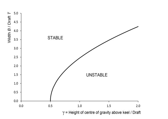
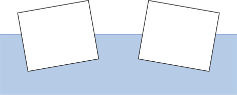
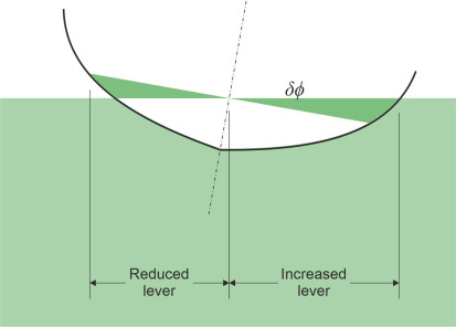
In contrast, a ship that corresponds to a point below the curve will not stay upright even in calm water. Instead it will rotate, and if not inundated by water pouring over the gunwales, may come to rest with its deck at an angle to the water surface – it lolls either to port ot starboard as shown in figure 14. The two positions are mirror images of each other [12]; they are only marginally stable.
Figure 14
Influence of the ship’s dimensions
Now let’s look at the problem from a different point of view. Suppose you are designing a hull and the calculations show it will be unstable under certain loading conditions: what can you do about it? In the automotive field, if a prototype car overturns during a test, the designer will make it wider by planting the wheels further apart, and probably reduce the height as well. Likewise, if you are concerned about the stability of the ship on your drawing board, you’ll want to increase the width of the hull, and figure 13 confirms that for a rectangular box, the wider the beam the greater the margin of stability. More often than not, the customer will want to keep the volume displacement and overall length unchanged, which means that the submerged cross-sectional area at each point along the hull is fixed in advance. Hence in order to meet the customer’s requirements, you’re really obliged to do two things: (a) increase the width and (b) reduce the depth of the hull in inverse proportion. Will this work?
To find out, we must derive an expression for the height \(\overline{\text{MG}}\) of the metacentre above the centre of mass in terms of the hull width or beam \(B\), while simultaneously keeping the draft \(T\) proportional to \(1/B\). The working is set out in Appendix 1. We assume that the hull structure, engines, fuel and cargo are arranged in such a way that the height of the centre of mass above the keel also varies in proportion to \(1/B\). We find that
(15)
\[\begin{equation} \overline{\text{MG}} \quad = \quad k_{1} B^{3} - k_{3} B^{-1} \end{equation}\]where \(k_1\) and \(k_3\) are positive constants. The right hand side always increases with increasing \(B\), so that under the assumptions made, the margin of stability improves when the hull is widened.
Different hull cross-sections
This is not surprising – if you want to pile a heavy load on the deck, your best bet is a raft: it is wide, it has a shallow draft, and it won’t roll over. But neither will it manoeuvre easily in and out of port, sail at a competitive speed, or ride smoothly over the waves, all of which call for a hull that is several times longer than it is wide. In principle, there are many alternatives shapes for the hull cross-section, all having different metacentric heights, and to give you some idea of the range of variation, four hypothetical profiles are shown in figure 15. In each case the centre of gravity is assumed to lie on the waterplane, and all have the same cross-sectional area, so you might expect them to have roughly the same displacement.
Figure 15
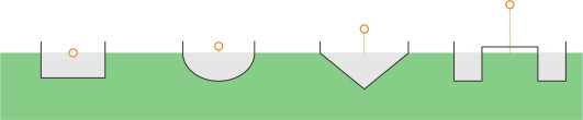
The first three are mono-hulls, all having the same ratio of beam to draft, which for the purpose of this exercise is fixed at 2.5, a broadly representative figure for commercial vessels. Starting on the left, the first cross-section is rectangular in shape. The second is semi-elliptical, while the third is an isosceles triangle. The odd one out is the twin-hull vessel on the right, whose beam is four times the draft, a more realistic ratio for a hull of this type. For each hull, your author has calculated the metacentric height from first principles, and the position of each metacentre is represented by a red circle. As you might expect, the twin-hull configuration is potentially the most stable of the four. More surprising, however, is the fact that of the remaining three, the triangular and elliptical cross-sections appear to perform better than the rectangular box. The reason is that all are assumed to have the same ratio of beam to draft as well as an identical area of submerged cross-section. This makes the triangular and elliptical cross-sections wider than the box, and as a result, they yield a greater second moment of area.
If we set up the problem in a different way, and stipulate instead that all four cross-sections have the same width, the results come out differently with the ranking order completely reversed. This is probably a more realistic scenario, because in practice, the hull width is a key constraint: all ships have to berth in a dry dock from time to time, and many are required to navigate canals such as the Panama Canal and the Suez Canal. So for a large vessel, the width is essentially pre-determined, and a rectangular cross-section is the preferred option.
Notice that all the vessels shown in figure 15 have vertical sides. However, this is not necessarily the case for leisure craft – particularly yachts and rowing boats – where the hull width is less of a constraint. For much of their length, the hull sides are angled outwards above the waterline, and this overhanging profile introduces a new component into the stability equation. Imagine a sailing dinghy heeling to starboard. Just like a rectangular box, it will displace a wedge of fluid on the starboard side of the waterplane. But unlike the wedge displaced by a rectangular box, its width increases with increasing angle of heel as shown in figure 16. At the same time, the wedge vacated by the hull on the port side shrinks, and when acting together, the changes in the wedge geometry greatly increase the righting couple, which helps a sailing dinghy to avoid capsizing in a strong wind.
Figure 16
A cautionary note
At this stage perhaps, we should remind ourselves that the metacentric height tells us little about a ship’s stability in rough water - it’s merely a starting point. The concept of hydrostatic stability applies only to disturbances in which the hull rotates through a small angle away from the vertical, because for larger angles of heel, the assumptions underlying equation 8 break down. To check what happens with large angles of heel, the designer will carry out computer analysis. The results are usually expressed as a set of curves. Each curve is a plot of the restoring couple or righting lever against the angle of heel. You would expect the righting couple to be small at small angles of heel but to increase for larger ones. However there comes a point where a ship heels over at a very large angle and the restoring couple actually diminishes because the gunwale on the ‘low’ side is below the waterplane and water pours over it onto the deck. At this point no further buoyancy is available to generate a righting action (figure 17). When the lever falls to zero the ship will capsize.
Figure 17
To support the theoretical calculations, in years past a shipbuilder might carry out an inclining test on a newly constructed hull by placing a heavy weight on the deck and moving it from one side to the other. Such a test was carried out on the Swedish flagship Vasa while it was being fitted with an extra gun deck in 1628. Worried about its stability, the captain ordered 300 sailors to run across the deck from side-to-side and back again. The ship rolled so badly that he stopped the test after three passes. Nevertheless, the ship was ordered out to sea next day and sank shortly after leaving harbour.
List and loll
So far we’ve assumed that a ship’s centre of mass lies on the middle line plane so it floats upright in calm water. But if the contents are stowed asymmetrically the ship will heel permanently to one side - it will list. A list compromises the safety of the vessel because it reduces the freeboard on one side, and hence the angle at which the ship can safely roll in a rough sea.
Angle of loll
Surprisingly perhaps, a ship can list permanently to one side even if the contents are stowed with the centre of gravity on the middle line plane. The condition, known as loll, can occur when the metacentric height is negative. The ship then becomes unstable at small angles of heel and incapable of maintaining an upright position. But instead of turning over completely, some ships will come to rest at an angle of several degrees away from the vertical as shown earlier in figure 14, because the displaced water produces a righting moment that prevents a total capsize. In this position, the ship adopts a somewhat precarious equilibrium at an angle known as the angle of loll [12]. After any small disturbance the ship will return to this angle, but the righting lever is small, and in a rough sea the vessel is unsafe. For a vessel with vertical sides - a ‘wall-sided’ vessel - one can quantify the righting lever quite accurately and predict the angle of loll. A sample calculation is set out in Appendix 2.
Loose cargo
The shape of the hull is not the only factor affecting the lateral stability of a ship. It seems that the way a cargo is distributed can have a marked effect and even cause it to capsize. That’s why a ship’s master is expected to undergo training not just in navigation and seamanship but also how to calculate the metacentric height together with other stability parameters. Before the start of each voyage, calculations are carried out that take into account how the loading pattern will change as fuel is consumed en route. And it’s important that the cargo remains firmly in place throughout. Any movement can alter the margin of safety, which explains why there are specific regulations covering the stowage of loose cargo such as grain. Liquid cargoes pose a special problem: ideally the tanks are subdivided so that the contents can’t slosh across the ship from side to side.
Since 1980, two passenger car ferries have capsized, both because they took in water, a liquid ‘cargo’ they weren’t designed to carry. The first case occurred on the 6 March 1987, when the Herald of Free Enterprise turned on its side just after leaving Zeebrugge, resulting in the loss of 193 passengers and crew. The bow doors had been left open and within minutes, seawater began to flood in. Once inside, it took only a few centimetres of water to make the ship unstable because the vehicle parking deck extended without a break across the full width of the vessel. When the ship heeled, the water slid across the deck and accumulated along one edge. There, it applied an upsetting lever that made the heel worse and increased the rate of inundation. The second case resulted in even more loss of life. On 28 September 1994, the passenger ferry Estonia sank in the Baltic Sea while on a routine voyage between Tallinn and Stockholm. Altogether, 838 passengers drowned. It appears that the bow door broke away in heavy seas and the inner door seals failed, again allowing water to pour into the main hold.
Conclusion
Design standards and operational procedures have since been tightened so that disasters of this kind are much less likely. In theory, it’s possible to configure a ship’s hull so that it cannot possibly roll over, by making the hull very wide and shallow like a pontoon or a raft. However, a pontoon doesn’t cut through the water efficiently and neither does it behave well in a rough sea. As we shall see later in Section M1115, getting the hull shape right involves a subtle compromise between stability and seakeeping.
Appendix 1: The effect of varying the hull proportions on the position of the metacentre
Suppose a designer is worried about the hydrostatic stability in roll of a vessel now on the drawing board. It would appear sensible to increase the width of the hull, but in order to maintain the same length and displacement, one would also have to reduce the draft in inverse proportion so the cross-sectional area at each point along the hull is unaffected. Will this always work, and how can one be sure?
From equation 2 we see that the second moment of area of the waterplane section is given by the expression
(16)
\[\begin{equation} I_{\text{area}} \quad = \quad \frac{2}{3} \int \limits_{0}^{L_{WL}} Y^{3} dX \end{equation}\]in which the quantity \(Y\) is a function of the distance \(X\) from the stern. It traces out the profile of the waterplane section, being half the width of the submerged hull measured at each point along the length of the ship. In what follows, we’ll assume that the length \(L_{WL}\) remains constant throughout. Assuming that the width is changed in the same ratio at each point, then \(I_{\text{area}}\) is proportional to the cube of the maximum width or beam \(B\), so we can write equation 8 for the height \(\overline{\text{MB}}\) of the metacentre above the centre of buoyancy in the following form:
(17)
\[\begin{equation} \overline{\text{MB}} \quad = \quad \frac{I_{\text{area}}}{\nabla} \quad = k_{1} B^3 \end{equation}\]where \(k_1\) is a positive constant.
We can now determine the metacentric height \(\overline{\text{MG}}\) by subtracting from \(\overline{\text{MB}}\) the distance \(\overline{\text{GB}}\), the vertical separation between the centre of buoyancy and the centre of gravity. It will help us to write this latter quantity as the difference between the height \(\overline{\text{GK}}\) of the centre of gravity above the keel, and the height \(\overline{\text{BK}}\) of the centre of buoyancy above the keel. We’ll assume \(\overline{\text{GK}}\) and \(\overline{\text{BK}}\) both scale up and down in proportion to the draft \(T\), putting \(\overline{\text{GK}}\) equal to \(\gamma T\) and \(\overline{\text{BK}}\) equal to \(\beta T\), where the dimensionless parameters \(\gamma\) and \(\beta\) are both positive constants. The result is
(18)
\[\begin{eqnarray} \overline{\text{MG}} \quad & = & \overline{\text{MB}} - \overline{\text{GB}} \quad = \quad \overline{\text{MB}} - \overline{\text{GK}} + \overline{\text{BK}} \nonumber \\ & = & \quad k_{1} B^{3} - \gamma T + \beta T \nonumber \\ & = & k_{1} B^{3} - \left(\gamma - \beta \right) k_{2} B^{-1} \end{eqnarray}\]where \(k_2\) is another positive constant. Typically, \(\gamma\) is around 1.0 and \(\beta\) around 0.5, so the quantity \(\left( \gamma - \beta \right) k_2\) is a positive constant and we can write equation 18 as
(19)
\[\begin{equation} \overline{\text{MG}} \quad = \quad k_{1} {B^3} - k_{3} B^{-1} \end{equation}\]where \(k_3\) is another positive constant. The right-hand side of equation 19 is an increasing function of \(B\), so that under the assumptions made, the metacentric height and hence the margin of stability increases when the hull is widened.
Appendix 2: The wall-sided formula
If the sides of a ship are vertical for some distance above and below the waterline, the hull is described as ‘wall-sided’. Many cargo ships are wall-sided or approximately so, and this feature enables one to extend the stability analysis set out in Appendix 1 to apply to larger angles of heel. We’ll follow the same sequence of logic. Imagine the ship heeled to starboard, this time at an angle \(\phi\). The angle can be as large as we please provided the starboard gunwale does not dip below the water surface. Consider a transverse slice of thickness \(\delta X\) a shown in figure 18. The cross-sectional area of the immersed wedge on the starboard side is equal to
(20)
\[\begin{equation} \frac{1}{2} \times \text{base} \times \text{height} \quad = \quad \frac{1}{2} \times Y \times Y \tan \phi \quad = \quad \frac{1}{2} Y^{2} \tan \phi \end{equation}\]and the volume of displaced water is \(\frac{1}{2} Y^{2} \tan \phi .\delta X\). It produces an upthrust equal to
(21)
\[\begin{equation} \frac{1}{2} \rho g\ Y^{2} \tan \phi .\delta X \end{equation}\]Figure 18
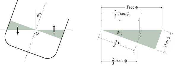
As shown in figure 18, the upthrust effectively acts at the centroid of the green triangle, at a horizontal distance \(c\) from O given by
(22)
\[\begin{eqnarray} c \quad & = & \quad \frac{1}{2}\left( \frac{2}{3} Y \cos \phi \ + \frac{2}{3} Y \sec \phi \right)\quad \nonumber \\ & = & \quad \frac{2}{3} Y \cos \phi \left[ \frac{1}{2} \left( 1 + \sec^{2}\phi \right) \right] \nonumber \\ & = & \quad \frac{2}{3} Y \cos \phi \left( 1 + \frac{1}{2} \tan^{2} \phi \right) \end{eqnarray}\]and this upthrust exerts a righting couple \(\delta R\) in the anti-clockwise direction about the origin O given by
(23)
\[\begin{eqnarray} \delta R \quad & = & \quad \text{upthrust}\ \times \ \text{lever arm} \nonumber \\ & = & \quad \left( \frac{1}{2} \rho g Y^{2} \delta X.\tan \phi \right)\ \times \ \left[ \frac{2}{3} Y \cos \phi \left( 1 + \frac{1}{2} \tan^{2} \phi \right) \right] \nonumber \\ & = & \quad \frac{1}{3} \rho g Y^{3} \delta X.\sin \phi \left( 1 + \frac{1}{2} \tan^{2} \phi \right) \end{eqnarray}\]We obtain the righting couple associated with the extra wedge of water displaced on the starboard side by integrating along the length of the ship, and to get the overall value \(R\), double the result to allow for the additional righting couple produced by the emerging wedge on the port side to get
(24)
\[\begin{eqnarray} R \quad & = & \quad 2\ \times \ \frac{1}{3} \rho g sin \phi \left( 1 + \frac{1}{2} \tan^{2} \phi \right)\ \int \limits_{0}^{L_{WL}} Y^{3} dX \nonumber \\ & = & \quad \rho g I_{\text{area}} \sin \phi \left( 1 + \frac{1}{2} \tan^{2} \phi \right) \end{eqnarray}\]Figure 19
The wedge righting moment \(R\) is a pure couple that effectively shifts the centre of buoyancy through a horizontal distance \(h\) to a new location B\('\) as shown in figure 19. The distance \(h\) is given by
(25)
\[\begin{eqnarray} h \quad & = & \quad \frac{\text{Wedge righting couple}}{\text{Buoyancy force}} \quad \nonumber \\ & = & \quad \frac{ \rho g I_{\text{area}} \sin \phi \left( 1 + \frac{1}{2}\tan^{2} \phi \right)}{\rho g \nabla } \nonumber \\ & = & \quad \frac{I_{\text{area}}}{ \nabla } \sin \phi \left( 1 + \frac{1}{2} \tan^{2} \phi \right) \end{eqnarray}\]The buoyancy force now acts along the vertical line through B\('\), which intersects the centreline of the hull at P. Since in the triangle PBH, the base \(h\) is equal to \(\overline{\text{PB}} \times \sin \phi\), it follows that
(26)
\[\begin{equation} \overline{\text{PB}} \quad = \quad \frac{h}{\sin \phi } \quad = \quad \frac{I_{\text{area}}}{\nabla } \left( 1 + \frac{1}{2} \tan^{2} \phi \right) \quad =\quad \overline{\text{MB}} \left( 1 + \frac{1}{2} \tan^{2} \phi \right) \end{equation}\]As the heel angle \(\phi\) tends to zero, the distance \(\overline{\text{PB}}\) converges on the metacentric height as previously defined.
Referring to triangle PGR in the diagram on the right-hand side of figure 19, the distance \(\overline{\text{PG}}\) can be expressed as follows:
(27)
\[\begin{eqnarray} \overline{\text{PG}} \quad & = & \quad \overline{\text{PB}}\ -\ \overline{\text{GB}} \nonumber \\ & = & \quad \overline{\text{MB}} \left( 1 + \frac{1}{2} \tan^{2} \phi \right)\ -\ \overline{\text{GB}} \nonumber \\ & = & \quad \overline{\text{MB}} - \overline{\text{GB}}\ +\ \frac{1}{2}\overline{\text{MB}} \tan^{2} \phi \nonumber \\ & = & \quad \overline{\text{MG}} \ +\ \frac{1}{2} \overline{\text{MB}} \tan^{2} \phi \end{eqnarray}\]Hence value of the righting lever \(r\) in this case is given by
(28)
\[\begin{equation} r \quad = \quad \overline{\text{PG}} \sin \phi \quad = \quad \left( \overline{\text{MG}}\ +\ \frac{1}{2}\overline{\text{MB}} \tan^{2} \phi \right) \sin \phi \end{equation}\]Within this formula, both the metacentric height \(\overline{\text{MG}}\) and the height \(\overline{\text{MB}}\) of the metacentre above the centre of buoyancy are fixed parameters - they don’t vary with the angle of heel. Under normal conditions the metacentre will lie above the centre of gravity, and the righting lever increases steadily with the angle of heel, which ensures the stability of the vessel. But if the ship is loaded in such a way that the centre of mass rises above the metacentre, \(\overline{\text{MG}}\) will be negative and the righting lever, zero in the upright position, will become negative if the attitude of the ship is disturbed. It will heel over, and as it does so the second term \(\frac{1}{2} \overline{\text{MB}} \tan^{2} \phi\) inside the braces will grow in size and since it is always positive will at some point cancel out the negative term so that \(r\) increases and passes through zero again. At this point, the hull has reached a new equilibrium that is stable in principle although only feebly so. The angle at which this occurs is known as the angle of loll. You can see by equating \(r\) to zero that \(\phi_\text{loll}\) satisfies
(29)
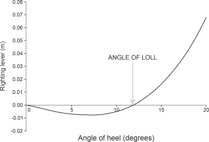
\[\begin{equation} \tan \phi_{\text{loll}} \quad = \quad \pm \sqrt{-2 \frac{\overline{\text{MG}}}{ \overline{\text{MB}}}} \end{equation}\]The hull won’t float upright, but rather, it will loll to one side. Typically, the righting lever is small so there is little resistance to being disturbed; the ship can loll from one side to the other and will readily capsize. As an example we can plot the value of the righting lever for a hypothetical hull typical of a small cargo ship. We’ll take the metacentric height as 4.0 m. The cargo is loaded so the centre of mass lies 0.1 m above M so that \(\overline{\text{MG}} = -0.10\)m and the ship is unstable. The righting lever is plotted in figure 20 for various angles of heel. For angles of heel up to \(12^{\circ}\) the value is negative and very small (just a few millimetres) becoming positive thereafter. The angle of loll is therefore \(\pm 12^{\circ}\).
Figure 20