G.2019
Machines in motion
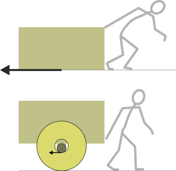
As children we are fascinated by wheels, in fact anything that goes round, like a spinning top, a gyroscope, or a bicycle wheel. The magic fades as we grow older and become used to the wheel as a part of everyday life. With wheels, we can build vehicles that enable us to move things more easily than dragging them along the ground. But do we understand how a wheel actually works? Viewed at one level, it’s a simple device, but if we look more closely, we’ll see a lot going on between the vehicle and the track on which it stands. Imagine you are trying to move a heavy load. You put it in a box, then make a pair of wheels, two flat discs each with a hole drilled through the middle. Now if you push an axle through the holes and fix it to the box, you will have made a cart that can be hauled to and fro with relatively little resistance. In the Sections that follow, you’ll see why: as shown in figure 1, the problem has shifted from one kind of interface to another, from the box dragging along the ground to the wheels rotating around the axle. Not only are the contact surfaces smoother, but the speed at which they are sliding over one another is much less than the speed of the cart. In fact, one can eliminate friction almost entirely, by enlarging the hole and inserting rollers between the wheel and the axle to create a ‘roller bearing’. However, there is a problem. With or without roller bearings, putting a load on wheels changes its relationship with the ground.
Figure 1
Contact
In school physics, the wheel is pictured as a rigid circular disk, and it rolls along a flat surface like a coin on a marble slab. The slab is smooth and hard and the rim is narrow, so at any given moment, the wheel is supported at a single point (figure 2). Fine, you might say, but since no part of the wheel touches the slab for a finite period of time, how does the wheel ‘know’ which direction it is supposed to be rolling in? Actually, it doesn’t need to. The idea of a perfectly circular wheel running on a perfectly flat surface exists only in the imagination.
Figure 2
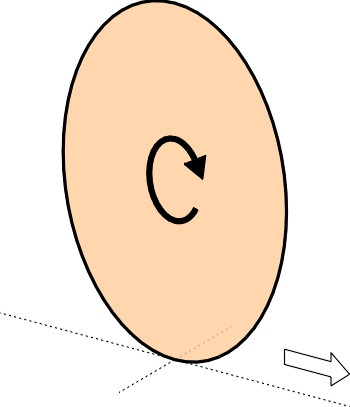
The rolling wheel
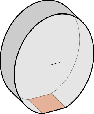
A real wheel carries a load, however small. The load passes through the rim into the slab, and if the area in contact with the slab were infinitesimally small, the stress, which is equal to the force divided by the contact area, would be infinite. No material can withstand infinite stress: it must deform or break. So locally, the shape of the wheel and shape of the slab must change (figure 3). Within the area of contact, the wheel rim is flattened and a depression forms in the supporting slab. The depth of the depression depends on the hardness of the material. On a metalled carriageway, the deflection is small and it disappears after the wheel moves on. On soft ground, the soil may deform so the wheel leaves a permanent rut.
Figure 3
Not all wheels are hard: cars and trucks, for example, have squashy rubber tyres. Each presses on the road surface over an area about the size of your hand. The contact patch bridges across chippings in the road surface that would otherwise make the wheel rattle up and down, and consequently, the pneumatic tyre helps to smooth out the ride - without it, road travel at present-day speeds would be intolerable. The tread does something else as well and it’s just as important: it grips the surface so the vehicle doesn’t slide out of control.
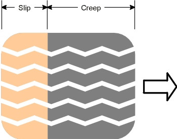
Exactly what happens within the area of the contact patch when the driver steers round a curve or applies the brakes is quite complicated. Contrary to the classical laws of friction, a large contact patch grips the road better than a small one. The rubber doesn’t simply ‘stick’ to the road, but creeps along the surface, draping itself over the stones that project from the asphalt. Because of the relative motion, the stones plough through the rubber, and towards the rear of the contact patch, the relative motion increases sharply and there is a well-defined area of slip (figure 4). And you’ll have noticed that a rubber tyre is noisy when driven at speed, because the rubber blocks in the tread slap the road surface one after another, trapping and releasing pockets of air. The abrupt pressure fluctuations are broadcast as noise whose frequencies are spread over a wide range, and in fact the tyres make more noise than the engine.
Figure 4
Railway wheels grip their track in a different way. A typical passenger coach has eight of them, all with steel treads that roll along steel rails. Each wheel carries a load of 10 tonnes, about the same as the total load carried by the rear axle of a double-decker bus. However, compared with a pneumatic tyre, the contact patch under a railway wheel is minute, only about the size of your thumbnail. Like a car tyre, it must support the wheel load, and transmit all the braking forces and most of the lateral forces that steer the wheels round curves in the track. (You may find the idea of steering a railway train rather odd, and we’ll try to explain it in a later Section.)
In fact the ‘real’ contact area is even smaller than it appears. Although the surfaces of the wheel and rail look smooth, they are not when viewed through a microscope. Consequently, within the contact patch there is very little contact at all. The load is focussed on the small surface peaks, where the stress (force divided by area) reaches gargantuan proportions (figure 5). The peaks are deformed and crushed, a process that generates high-pitched vibrations that make each wheel resonate like a church bell. Nevertheless, the peaks are small and the coach is well insulated so that from the passenger’s point of view, riding in a train nowadays is exquisitely comfortable, and offers a smoother ride than most other forms of transport.
Figure 5
On water
But not as smooth as a rowing boat (figure 6). In calm water, a passenger on a rowing boat feels no bumps or vibrations because the supporting forces are different. It’s buoyancy that keeps the vessel afloat: according to Archimedes’ Law, the upthrust equals the weight of water displaced, so that the sum of the pressures acting on each square millimetre of the hull surface combine to produce an upward force that exactly counterbalances the vertical load (if it didn’t, the boat would sink a little until it did). However, buoyancy alone is not enough. Have you ever dropped an empty box into a pool to see which way up it will float? As well as displacing the right amount of water, the box must be the right shape, so that if it rolls to one side, the changing pressure distribution in combination with its own weight restores it to an upright position – it rights itself automatically. Many early ships were lost because the criteria for stability were not properly understood, until the French mathematician Pierre Bouguer worked out a formula on which shipwrights could rely to predict the vessel’s behaviour. For me, in simplicity and elegance it ranks alongside Einstein’s famous \(E = m c^2\).
Figure 6

A ship can carry over a hundred thousand tonnes of cargo because unlike the load carried by a road vehicle, the burden is spread out over a large area. Of course there is a price for this: the hull surface creates a lot of friction that slows it down. But a small boat can be made to skate along the surface with only part of its hull in contact with the water, provided it is sufficiently light and powerful, with the keel sloping downwards slightly from stem to stern. At speed, it collides with the water particles and rams them downwards, and the reaction to this impact is what supports the hull. The process is called ‘planing’, and it’s the same process that occurs when you pick up a flat stone and skim it along the surface of a pond. Under these circumstances, the water behaves more like a solid than a liquid, so if you’re driving a speedboat in choppy water, you can expect a bumpy ride.
Given that the vessel will stay afloat, the next question is how to get it moving. On water, it’s difficult to propel a vehicle forward because there isn’t a firm surface to push against. Most vessels exploit the water’s inertia: they pick it up and throw it backwards, counting on the reaction to push the hull in the opposite direction. Aircraft do the same. Projecting fluid aft is the function of the propeller, and it works quite well, although it injects energy into the fluid as well as into the vehicle: a cargo ship, for example, creates a broiling jet of water that extends a kilometre or more aft, where the energy gradually dissipates.
In the air
An aircraft has to keep moving to stay aloft. The wings thrust the air downwards sufficiently fast to generate a reaction equal to the aircraft’s weight. Exactly how they do this we’ll examine in the last part of the web site - surprisingly perhaps, friction plays a crucial role. For now, we’ll observe only that the reaction appears as a pressure change over the wing surface. Unlike the pressure that supports a speedboat, most of the lift is provided not by air pressing upwards from below, but by suction on the upper surface, as if the wings were hanging from invisible wires. At least, that’s how it appears on the scale at which humans normally view things.
But if we look more closely, we see that the atmosphere consists of vast numbers of molecules. Unlike the molecules in a solid, they are darting about at random and often collide with one another as well as with any solid object that happens to get in the way. It is the collisions that we interpret as pressure. If large numbers impinge per unit area, the pressure is high, while if small numbers impinge, the pressure is low. At the molecular level, there is no such thing as ‘suction’, only a reduced frequency of impacts. Hence the notion of suction and that of molecular impact are alternative mind pictures that work best at different scales of measurement. So the question remains: why are the pressures different? You can find at least six distinct explanations for the ‘lift’ what keeps an aircraft flying, and we’ll be looking at some of them in their proper place. Incidentally, none refer to molecular impacts at all.
The vehicle and the track
When an aircraft stops, it drops. When overcome by waves, a ship will capsize. Trains occasionally leave the rails, and cars run out of control. Engineers who work in the sphere of transport worry about safety more than anything else. They worry because no-one can design, build and operate a vehicle that is totally safe. Any such enterprise carries risks, and the risks are greater if the design is original or relies on new technology. One can only try to imagine them in a systematic way, then configure the design so that the worst doesn’t happen, or at least, not very often.
Support
An important factor is the condition of the supporting track. The weight of a land vehicle such as a truck or a railway train is carried by its wheels, and the load carried by each wheel is in turn transmitted to the track through the contact patch. The smaller the contact patch, the greater the stress (force per unit area), and the greater the rate of wear. Whether it’s made of concrete, steel, or compacted earth, the purpose of the track is to spread the wheel loads over the widest possible area so the vehicle doesn’t sink into the ground. The lines of stress branch out within the track and its supporting foundation like the roots of a tree, so that when they reach ‘formation level’ at the base, they are safely absorbed by whatever material lies below.
Have you ever wondered, though, what happens underneath a ship, and how its weight is conveyed to the seabed? Here, the load path is different because the burden is transmitted through a large area of hull. Imagine a cargo ship anchored in still water, and choose a particular point P on the hull surface. By definition, the pressure that the hull applies to the water at P is equal to the water pressure at that point before the ship arrived, so there’s no danger of the water collapsing under its weight. In other words, the water doesn’t ‘notice’ the ship’s presence - there’s no pressure change under the bilges. So where does the load go? As we’ll see in a later Section, it is carried to the earth not directly below the hull, but spread out over the whole of the ocean floor.
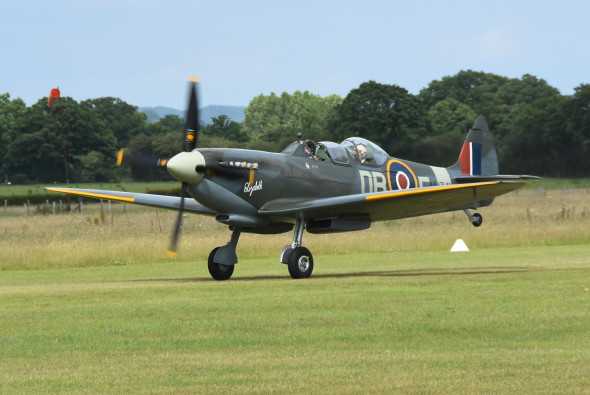
Aircraft behave differently. As we saw earlier, their wings push the air downwards, fast enough to generate a reaction that keeps them in the air. The downdraught also triggers vortices that trail energetically from the wingtips and together, they create pressure variations in the surrounding atmosphere. These spread out and eventually reach the ground, so in principle, one should be able to detect the passage of the aircraft in their ‘shadow’. Although I haven’t come across any data to confirm this for aircraft in normal flight, we know that when a plane flies close to the ground, there is a marked interaction between the wings and the ground surface that the pilot senses as an air ‘cushion’ (figure 7). In fact, ekranoplans rely entirely on this cushion for support.
Figure 7
Uniquely, at high altitude above the earth’s atmosphere, there’s nothing outside for a space vehicle to react against, so astronauts have to use whatever they have on board and throw it out. The stuff that propels a rocket is not just fuel, it’s also mass. When it burns, it expands rapidly and in the form of exhaust gases, squirts into the void. Again it’s the reaction that powers the spaceship, but the fuel tanks get lighter with every firing sequence until there is nothing left to throw away.
Control forces
So far we have dealt only with vertical forces of the kind needed to support the vehicle’s weight. Horizontal forces are needed too, to provide traction or thrust to make the vehicle speed up, slow down, or steer round a curve. Imagine you are running around your local park. Without horizontal forces, you couldn’t move at all, and if you did, you would skid along helplessly like a cartoon character on a frozen lake. We’ve already mentioned how ships create thrust. Early mariners relied on the pressure of the wind acting on their sails, but during the nineteenth century they harnessed steam power to drive paddlewheels and revolving propellers.
However, transport vehicles move a lot faster now than they did a few decades ago, and speed makes control more difficult. Some of the difficulties are built into the machine: a vehicle may get out of control because it is intrinsically unstable. For example, a car that oversteers will amplify the driver’s actions: a small deviation to the left or right will develop into a progressively tighter curve because the forces generated within the vehicle suspension tend to accentuate the swerve and make matters worse. Such behaviour is difficult for ordinary drivers to correct, and sometimes makes the car undriveable. Trains can snake from side to side in a phenomenon called ‘hunting’ that plagued steam railways well into the 1970s. Aircraft are subject to instability in three dimensions. Some aircraft can fly only with the aid of a computer that responds to deviations more quickly than the pilot can.
Vibration
Not all the things that engineers worry about are so dramatic, but they are no less interesting for that. For example, moving vehicles are prone to vibration, which comes mainly from two sources. The first is the surface on which the vehicle travels, such as a bumpy road, which will inject vibrations through the suspension into the body structure. The second is any assembly with rotating parts: if the rotating parts are out of balance, the assembly is liable to shake itself apart, and if it doesn’t, the vibrations will shorten the life of the machinery and also leak into the surrounding body structure. Quite often, the body structure will resonate in sympathy, making conditions unpleasant if not unbearable for passengers.
Resonance lies at the heart of several problems that have plagued vehicles in the past. Under certain conditions, the blades of a ship’s screw will emit a piercing squeal – a phenomenon known as a ‘singing propeller’. Worse is the vibration that used to occur with aircraft during the last century in which the whole wing or tailplane would start to shake, with the oscillations growing in amplitude as the frequency of eddies in the air flow approached the natural frequency of vibration of the structure. Known as aeroelasticity or ‘flutter’, it led to several crashes before designers were able to model the dynamics and cure the problem by stiffening the structure without adding too much weight or compromising the machine’s aerodynamic performance.
Resistance
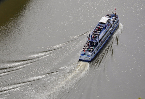
A moving vehicle leaves traces in its path: turbulent eddies in the air flow, rusting particles of steel along a railway track, the ‘V’-shaped wave pattern in a ship’s wake (figure 8), and rubber particles, bitumen and concrete dust stirred up from the road surface, together with a blanket of noise in towns and cities generated by moving vehicles of all kinds. There’s a common link: resistance. Resistance is a collective term for the unwanted forces such as friction and aerodynamic drag that slow a vehicle down. Some, such as friction, produce a tangible residue in the form of dust, while others don’t. Turbulence and noise are invisible and they occur on different scales, but both signify energy that is being dissipated into the atmosphere. Resistance losses of all kinds will be a recurring theme in this web site, not least because they increase sharply with vehicle speed. Other things being equal, they also increase with vehicle weight. The implications for energy consumption and climate change are obvious: in our parents’ generation, fuel was cheap, and if you wanted a big car or you wanted to drive fast you could buy a luxury model with a more powerful engine. But this is no longer a sustainable option, so engineers face a daunting task: to slim down vehicles, make them more efficient, and de-carbonise vehicle fleets worldwide by 2050 without bringing the world’s economy to a halt.
Figure 8
Where next?
Every moving vehicle makes contact with its surroundings. You’d imagine the process is easy to describe: it’s just different parts of the vehicle body surface pressing against or sliding over different surfaces and materials in the environment. In fact, the physics is not straightforward, and the closer you look, the more interesting it gets. The difficulties are underlined in the following statements by leading experts:
Road: ‘… many experts regard the mathematical physics of contact patch behaviour as among the most complex in any field of engineering’ [2].
Rail: ‘The railway train running along a track is one of the most complicated dynamical systems in engineering’ [4].
Marine: ‘The problem of a slender ship moving with forward velocity in a seaway … is beyond the present state of knowledge’ [3].
Air: ‘Most aerodynamic flows are quite complex, and … over the centuries humans have had plenty of trouble in attempting to understand and decipher them’ [1].
But the underlying ideas are perfectly accessible, and our aim is to bring them into focus so that non-specialists can understand how vehicles move, and compare their behaviour across different transport modes. From here on you can choose a particular mode such as Rail transport, and go straight to the introductory Section R2019. Alternatively, you can plough gently onwards, letting the system carry you through the different modes of transport in a pre-determined order: Road, Rail, Marine, Air (available some time in 2022), followed by a short review of Fluid Mechanics applied to moving vehicles of all kinds. We sincerely hope you enjoy the ride.
Acknowledgements
Figure 6: Photo of rowing boat on St. Herbert’s Island, https://www.geograph.org.uk/reuse.php?id=6224291, copyright D S Pugh and posted under Creative Commons license (accessed 02 July 2020).
Figure 7: Spitfire at low altitude, by kind permission of Barry Duffield Photography.
Figure 8: Ship’s bow wave, photo by Erich Westendarp from Pixabay, available at https://pixabay.com/photos/saar-saar-loop-excursion-ship-3410871/ (accessed 18 July 2021).