M.1717
Hydrofoils
As long ago as 1861, an Englishman called Thomas Moy discovered the principle of the hydrofoil. He wasn’t interested in boats. He was trying to develop an early form of flying machine, and having built a model wing, he was curious to know how it would perform. Unable to measure the lift accurately when it moved through the air, he tried ‘flying’ the model through water instead, by fixing it to a boat that he towed along the Surrey canal [8]. Although the experiment didn’t lead to a practical boat, it showed that wings can generate a considerable force, with the potential to support a craft weighing many tonnes. Over the decades, other inventors (notably Enrico Forlanini and Alexander Graham Bell) took up the idea and made it work, and by 1920, hydrofoil prototypes were breaking the world speed record [7].
Hydrodynamics
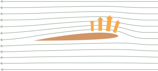
Anything that slices through the water can generate a lot of resistance so like an aircraft wing, a hydrofoil blade must be smooth and thin, with a ratio of thickness-to-chord in the range 0.075 to 0.09 [5] (see figure 1). Indeed, the foil works in the same way as an aircraft wing, and you’ll find the process described in more depth in Sections F1817 and F1816. It is inclined at a slight angle to the oncoming flow, which follows a curved path over the upper surface so that the streamlines are squeezed together above the leading edge and the particles are forced to speed up relative to the surrounding fluid (figure 2). In accordance with Bernoulli’s principle, the pressure falls and the blade is sucked upwards.
Figure 1
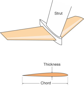
Figure 2
Lift
The lift is related to the speed and the density of the fluid medium in the same way as aerodynamic lift. For the simple case of a fully submerged horizontal foil [5], the vertical lift force \(F_L\) is given by:
(1)
\[\begin{equation} F_{L} \quad = \quad \frac{1}{2} \rho g V^{2} A C_{L} \end{equation}\]where \(\rho\) is the density of water, \(g\) is the acceleration due to gravity, \(V\) the velocity, \(A\) the plan area of the foil, and \(C_L\) the coefficient of lift. The lift coefficient is typically a little under 0.4, rising to 0.7 for a new foil in clean condition [5]. Its value depends almost entirely on the geometry of the cross-section, being roughly constant regardless of its size, or the speed at which the foil is travelling through the water. Since the lift increases with the square of speed, provided it is moving fast enough you don’t need much foil to support a considerable weight. Let’s suppose the foil has about the same area as a coffee table, say one metre in span by 40 cm chord. At a speed of 40 knots (20.6 m/s) with a lift coefficient of 0.7, the lift force will be \(0.5 \times 1025 \times 9.81 \times {20.6}^{2} \times 0.4 \times 0.7\), which comes to \(596\) kN or a little over 60 tonnes.
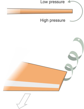
When moving at speed, a foil produces a characteristic wake. The curved upper surface sucks the water particles downwards, and being deflected, they acquire momentum in a new direction. This has two consequences. First, the downward force on the fluid produces an equal and opposite reaction, which is the lift applied to the hydrofoil blade. Second, since water is not a compressible fluid, any downward motion must be compensated by upward motion elsewhere, and in fact, water flows in from the sides to replace the deflected particles. The result is a circular pattern of motion when viewed from in front: a vortex that trails behind the outer extremity of each foil blade (figure 3). As explained in Section F1816, a similar phenomenon occurs with an aircraft wing.
Figure 3
Drag
A formula similar to equation 1 can be applied to predict the resistance associated with a marine hydrofoil, which like the lift force, is proportional to the area of the foil and also to the square of the vehicle speed. The resistance has several components, among them the induced drag, which is an inevitable consequence of creating lift, because the lift is the mirror image, if you like, of the downwash that the foils induce in the water, and this downwash dissipates kinetic energy supplied from the ship’s propulsion system. You can find more details together with typical drag coefficients in [5] and [2]. Here, we’ll focus on a single number, the ratio of drag to lift, which in a compact form reveals much about a hydrofoil’s performance. The blades don’t support the hull properly until it is going fast enough to rise clear of the water; there is a resistance ‘hump’ at a speed typically a little below 20 knots, then the resistance falls as the speed increases towards the value required for take-off. At take-off the lifting surfaces are working at close to their optimum efficiency, with a drag-to-lift ratio of around 0.05, but afterwards the ratio increases again, finally reaching 0.1 or thereabouts at maximum speed. In short, this means that the engines have to provide a thrust equal to an amount between 5\(\%\) or 10\(\%\) of the vehicle’s weight, possibly less than one half of the equivalent for a planing craft [2].
Cavitation
However, any marine hydrofoil is subject to a particular limitation: there is an upper bound to the lift it can produce regardless of the speed at which it moves through the water. This is because the suction cannot fall below a threshold value known as the vapour pressure, the pressure at which the liquid surface vaporises: in other words, it boils. As the speed of the vessel increases, small bubbles appear initially at the wingtips, and later on the upper face and at the joints with the struts. As each bubble moves downstream away from the zone of low pressure, the vapour inside condenses and the bubble implodes (figure 4). Because water is almost incompressible, the implosion creates a shock wave that radiates into the surrounding fluid where it can cause significant damage. The process is known as cavitation, and it can occur on the surface of any object moving through a liquid at high speed. We’ll look at it again more closely in Section M1410.
Figure 4
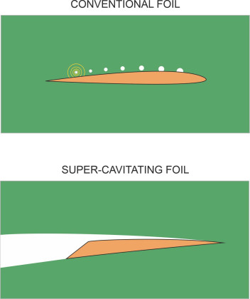
The propensity for cavitation depends on depth. If the foil is positioned deep below the surface where the static pressure is high, the pressure on the upper face can fall through a large range without dropping below the vapour threshold, so there will be plenty of lift available. By contrast, close to the surface, the static pressure is low, and a small pressure reduction on the upper face will result in cavitation under a relatively light load [5] [7]. So the most obvious way to avoid cavitation is to mount the foil on a long strut deep under the water. The greater the depth, the greater the potential lift and the greater the speed that can be achieved without cavitation. A less obvious solution is to encourage cavitation. Instead of bubbles, a continuous cavity is created across the upper surface of the foil in which the pressure is equal to the vapour pressure. A foil designed to operate in this mode is known as a super-cavitating foil. As shown in the lower part of figure 4, the cross-section is quite different from a conventional foil. It has a sharp leading edge and the upper face terminates with an abrupt change in angle at the trailing edge, designed so the cavity persists sufficiently far downstream for its collapse not to harm the foil. The designer can compensate for the limited pressure difference and the reduced lift by increasing the foil’s plan area [5].
While we’re on the subject it’s worth mentioning a related phenomenon known as ventilation. Ventilation occurs around a body such as a supporting strut that penetrates the water surface (as opposed to lying completely submerged). If the strut cavitates, the bubbles may form a continuous tunnel that links the strut with the atmosphere above the water surface. At this point, the air can leak onto the upper face of a foil blade, where it has an effect similar to cavitation, raising the pressure and reducing the lift [3].
Figure 5
Different foil configurations
Putting wings under a boat raises some awkward questions. Let’s look at a common configuration like the one shown in figure 5, and focus on the leading foil under the bow. It resembles an aircraft wing, and is fixed to a strut that projects downward into the water. Suppose that the vessel is stationary and begins to accelerate. As the speed increases, the foil will rise until it lies only a short distance below the surface. We know that when a foil of this shape is less than a chord’s length away from the surface, the lift will decrease because the foil will cause the surface to deform - there is only a thin layer of fluid passing over the upper face and it can generate only a limited amount of suction. A depression appears in the water surface, together with waves rather like those created by a displacement hull [6]. This loss of suction near the surface effectively limits the ride height. But is there a corresponding limit that prevents the foil from sinking too deeply under the surface? According to theory, the lift is almost independent of depth so there is very little restoring force that might help to establish an equilibrium position. Unlike the wheel of a car that rests on the road surface, a hydrofoil blade doesn’t rest on anything solid and doesn’t ‘know’ when it has reached the correct depth. Hence, a hydrofoil craft lacks inherent stability: if it rolls to one side, there are no forces acting on the foil blades that might restore it to an upright position.
Lifting surfaces
Early pioneers found a simple way round the problem. Instead of a single foil at each support location, they arranged a set of foils between two vertical struts like the rungs of a ladder. With such a ‘ladder foil’, a deflection upwards or downwards from its design elevation leads to a lesser or greater lift force according to the number of foils immersed in the water, and the variable restoring force makes the system stable. Another solution was to bend the wings upwards in the form of a vee, and extend them so they project outwards on either side of the vessel (figure 6). If the hull rises, the proportion of foil that is submerged under the water will diminish, and the lift will decrease. On the other hand if the hull descends, the area of submerged foil will grow and the lift will increase. In either case, there is a restoring force that nudges the foil back to an equilibrium position. Just like the sprung suspension of an automobile that keeps the body at a more-or-less constant height, the system is stable. And a surface-piercing hydrofoil not only controls the ride height, but also stabilises the vessel against pitch and roll.
Figure 6
However a surface-piercing foil has two disadvantages. The first is that whatever the ride height, part of the blade is always travelling at or near the water surface, so that cavitation is inevitable [7]. At higher speeds there is a risk that the cavitation produces a continuous tunnel that extends from the water surface towards the centre of the vee, which causes the foil to ventilate and lose lift. This can be remedied by means of ‘fences’, small vertical fins spaced at intervals along the upper face of the foil that effectively isolate the inner section. The second disadvantage is that a surface-piercing foil can be large and unwieldy, and because it projects outside the plan area of the hull, it can easily be damaged when the vessel approaches a wharf or quayside. Therefore special facilities are needed at each port of call, including a long gangway to bridge the gap between gunwale and quay.
Technically, a more sophisticated solution is to retain the simple foil configuration shown in figure 1 but to add flaps to the trailing edges that can swivel up and down to vary the lift. The flaps are managed automatically by a computer control system to keep each strut at an appropriate depth below the water surface. The system (a) adjusts the ride height in response to any change in speed, (b) keeps the vessel upright at a designated angle of trim, and (c) compensates at least partially for disturbances caused by sea waves. Any failure at speed could be catastrophic so the system must be extremely reliable. In fact, with a configuration such as the one shown in figure 5 as adopted for the Boeing Jetfoil, the forward strut swivels and acts as a rudder, while the port and starboard ailerons at the rear can be controlled independently to make the craft ‘bank’ in a turn rather like a tilting train.
Supporting struts
Foils are usually mounted on vertical struts that are cantilevered downward from the hull and support the whole weight of the vessel. But how many struts are needed? The problem is rather like putting wheels on a car: how many wheels and where should they go? A selection of alternative configurations can be found in [7]. For fast passenger ferries engaged in commercial competition, the preferred solution is to have three struts. Some vessels have two struts at the bow with a large foil blade spanning between them and a single strut at the rear. Others follow the reverse arrangement with a single strut at the bow as shown in figure 5. You’ll recall from Section C1508 that a 3-wheeler vehicle is not very stable if the single wheel is placed at the front; it will roll over if the driver brakes suddenly during a turn. Fortunately, this doesn’t apply to a marine hydrofoil, because (a) it has no brakes and (b) rolling motions can be damped via computer-controlled flaps.
But there’s a limit to the size of vessel that can be supported on hydrofoils. It’s a matter of scaling. If you take an existing design and double all of its dimensions (including the thickness of the plating and structural members), the weight will increase by a factor of 8 whereas the area of the foils - together with the lift they generate - will increase only by a factor of 4. To raise the lift sufficiently to keep the vessel above water, the foils must increase disproportionately in size, and in theory, for a very large vessel the foils would be too large and too heavy to support their own weight [5]. As things stand, with existing craft of moderate size the foils and struts must be very robust, and although cast from expensive high-grade alloys they are account for around 10\(\%\) of the total weight of the vessel [5]. Few hydrofoil craft exceed 40 m in length, or weigh more than 250 tonnes.
Figure 7
Thrust
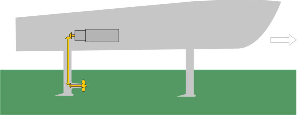
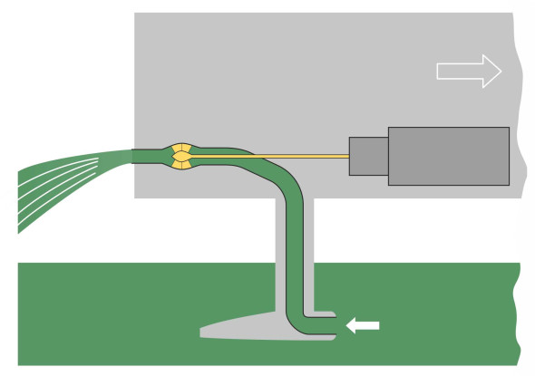
Finally we can turn to the question of power – not the power of the engine as such, but the drive mechanism that converts it to forward thrust. It’s not a trivial question. Assuming the thrust is delivered through a propeller in the normal way, the propeller will be located well below the keel so a conventional drive train won’t do. The simplest solution is to carry the torque through an intermediate shaft arranged vertically as shown in figure 7, linking the engine output with the propeller through two sets of bevel gears. A more elegant solution is a waterjet propulsion system. Essentially a propeller inside a tube, it draws in water and pumps it out of the stern at the level of the transom with considerable force (figure 8). It is the reaction that drives the vessel forwards, in the same way that the reaction to the exhaust gases propels a turbojet aircraft. You’ll find more on waterjet propulsion in Section M1405.
Figure 8
Behaviour in service
Speed and ride
To generate sufficient lift, a hydrofoil craft must reach a speed of at least 20 knots. Until it clears the water, there is considerable drag owing to friction on the underside of the hull. This drag represents a resistance ‘hump’ that inhibits take-off [5], but once it clears the hump, the vessel will manage up to 50 knots, far quicker than a conventional displacement vessel. This is why during the 1970s, hydrofoil craft made a significant impact on the market for fast passenger ferries. In practice, however, this represents an upper limit because cavitation tends to occur when the load per square metre on the foil reaches a level of around \(6 \times 10^{4}\) Nm\(^{-2}\) [1], which often occurs when the boat is travelling at a speed of 50-60 knots.
Another attractive feature of a hydrofoil craft is that it is partially protected from wave action. Since the blades are located well below the sea surface where the motions of water particles are less affected by what is happening on the surface, a hydrofoil craft rides more smoothly than a conventional hull, and more smoothly than a planing vessel (which jars on impact with each wave crest). Some hydrofoils can cope with waves of the order of 4 m in height, and under favourable conditions passengers describe the experience as ‘like a train ride’ [5].
Safety
Cavitation damage to the surface of a blade can be a nuisance but there is potentially a more serious problem. Below the water surface, the struts are vulnerable to impacts with their surroundings. Consequently, ship owners are concerned about the risk of grounding in shallow water, and collisions with submerged objects such as floating logs. If a strut breaks off, the hull may topple over at speed. At the time when hydrofoils first became popular fifty years ago, little was known about the risks, and it was widely assumed that a hydrofoil would operate safely in coastal waters provided the pilot could see what was happening in the water ahead and if necessary, take avoiding action. But in recent years, there have been casualties. In October 2015, more than half of the 174 passengers and crew travelling on a high-speed ferry from Macau to Hong Kong were injured when it hit an unidentified object floating in the water. It was the fourth accident on this route in two years, and the second involving an underwater object. Apparently, it took place after dark.
Maintenance
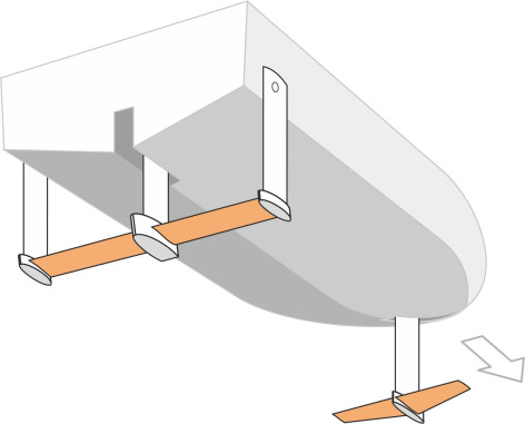
Unlike those acting on a displacement hull, the forces that support a hydrofoil craft are concentrated on relatively small areas of blade, and this can cause problems during service. The blade surfaces tend to become scratched and pitted, which raises the friction drag. To work efficiently, foils and the struts to which they are attached must be kept smooth and clean, which implies regular maintenance with the boat lifted out of the water [4]. The supporting struts for the hydrofoil craft shown in figure 5 are hinged so that the strut mounted under the bow can swing forward and retract clear of the water surface for easy access. The aft struts swing rearward.
Conclusion
We’ve now seen two ways of supporting a boat above or partly above the water: the planing hull as described in the previous Section, and the hydrofoil covered here. They work by deflecting fluid downwards, using the inertia of the water itself to create lift and reduce resistance. However, they both have disadvantages. A planing craft slams against the wave crests, which react almost like a solid material when encountered at speed, making the ride uncomfortable and even risky at high speeds. And while the hydrofoil by contrast provides a smoother ride, the struts and foils are liable to damage. As it turns out, however, in most countries hydrofoils have been replaced by cheaper and more robust alternatives, and the major fleets mothballed or scrapped. As we shall see in the next Section, there are other ways of supporting a sea-going vessel, using air rather than water to supply the lift.