© Harland & Wolff
M.1410
Marine propellers
When inventors dream up new ideas, they often look to the natural world for inspiration. They have been doing it for a long time. Over a hundred years ago, would-be aviators tried to build flying machines whose wings flapped up and down like the wings of a bird. In 1813, William Brunton created a steam locomotive driven by mechanical legs. In the maritime world, as long ago as the sixteenth century it was common practice to build ships whose sides were curved like the body of a fish. But no-one could make a ship move like one, because the sinuous motion of the body and tail is hard to replicate in a mechanical device. Until the mid-nineteenth century, this didn’t matter because ships were propelled by the wind. However, everything changed with the arrival of the steam engine, which could deliver power cheaply and consistently. The question was: how to transmit that power to the surrounding water?
The screw propeller
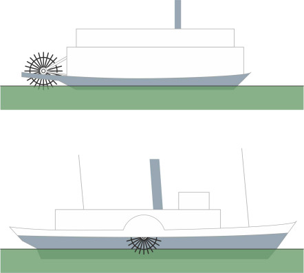
The most direct method seemed to be a paddle wheel: an assembly of blades on a rotating shaft so that each blade in turn dipped under the surface and pushed water aft. Towards the end of the 18th century, paddle-steamers began to emerge as a practical proposition (figure 1). There were two sorts. On the Mississippi and other great waterways of the USA, ‘stern-wheelers’ were propelled by a single paddlewheel aft, while in coastal waters around Europe, operators preferred side-wheelers such as Brunel’s Great Western. For a while, side-wheelers reached a level of efficiency comparable with that of a modern propeller [5]). But they suffered from two disadvantages. First, they needed relatively calm water for the paddles to bite into [37], otherwise, from time to time one wheel would be fully immersed in a wave crest while the other encountered a trough. This disrupted the transmission of power so the hull would yaw momentarily, and this in turn increased the drag. Second, with the ship unloaded, both paddle wheels rose out of the water (or nearly out of the water) and the ship couldn’t go anywhere at all. It wasn’t ideal for sea-going vessels, nor for vessels carrying heavy cargo. What was needed was a more compact device that worked in rough seas, and the answer was the screw propeller.
Figure 1
Evolution of the screw propeller
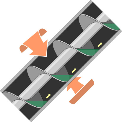
Compared with the wheel, which first appeared 3000 years ago, the propeller is a recent invention. It was originally envisaged as a helix that would screw its way through the water as if moving through plasticine or butter, each blade following several complete ‘turns’ around the shaft (figure 2). The idea was inspired by the Archimedean screw, named after the Greek philosopher and inventor. Around the year 300 BCE, Archimedes was commissioned by the King to design a warship, the Syracusia. Because of the way they were built, ships of that era tended to leak, and water quickly accumulated in the bilges. The Syracusia was a large vessel, and anticipating a problem, Archimedes adapted a device that first appeared in ancient Egypt where it was used to raise water from the Nile. Essentially it was a cylindrical tube containing a helical blade that could be rotated by hand. With the tube aligned at an angle of roughly \(45^{\circ}\) to the horizontal, the blade would carry water upwards from the bilges to the top of the tube, where it drained over the gunwale back into the sea (figure 3). It wasn’t a ‘hydrodynamic’ device because it didn’t pump the water under pressure. Instead, it worked like a conveyor belt, lifting chunks of fluid from a low level to a higher one. Nevertheless, it was the model on which many inventors based their hopes.
Figure 2
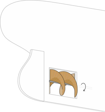
Figure 3
Historians have disputed who was the first to apply the helical blade successfully to propel a steamship. A prime candidate was Colonel John Stevens, who demonstrated the concept with the Little Juliane in Hoboken in the USA in 1804, but the idea didn’t catch on. During the late 1830s, John Ericsson and Francis P Smith independently developed screw propellers in the UK. Smith’s propeller was incorporated in the vessel SS Archimedes, while Ericsson went on to design successful steamships in the USA. After a while, it became clear that in rough water, the screw propeller worked better a paddle wheel, being less sensitive to waves and to the ship’s rolling motions [38].
Figure 4
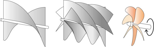
But it wasn’t very efficient. Eventually, engineers found that if they shortened the screw by cutting some of the blade away to leave a single turn, the thrust increased. A single turn was in fact sufficient: adding a second or a third turn didn’t move the water any faster than it was moving already, and in fact the extra surface area generated more friction. Subsequently, experiments showed that even a single turn was excessive, and more efficient forms of propeller were developed with several blades, each limited to a fraction of a turn. They were interleaved to create a multi-bladed propeller that looked more like a windmill than a screw (figure 4). Figure 5 shows the design Brunel adopted for the SS Great Britain after he scrapped his original plan to drive it with paddlewheels and installed a propeller instead. This more modern form of propeller looks very different from its predecessors, but shipwrights were accustomed to calling it a ‘screw’ and the name has stuck.
Figure 5
How it works
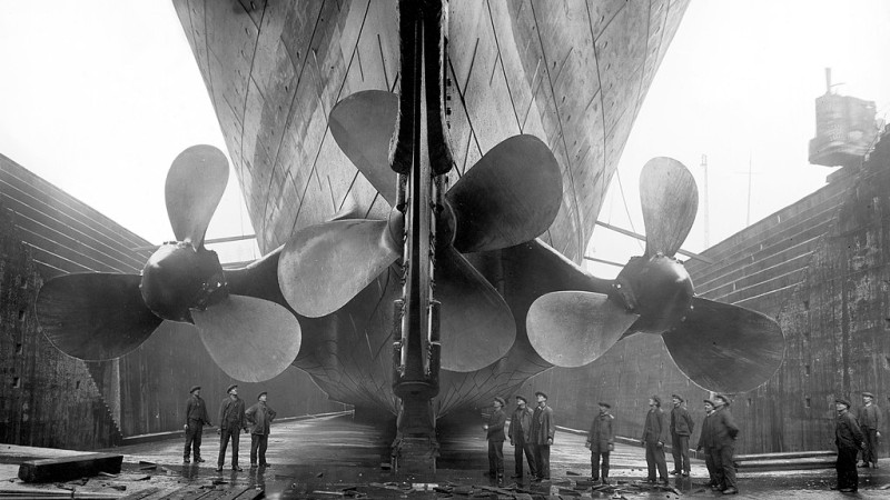
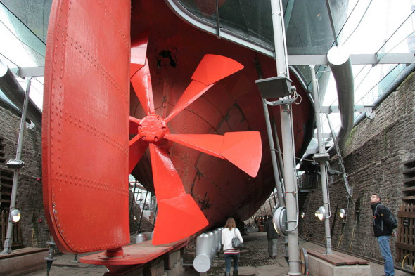
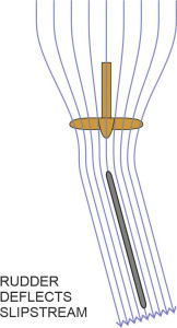
A ship’s propeller is normally hidden beneath the water surface, and when exposed, it looks small in comparison with the hull. Despite its small size, in hydrodynamic terms, the propeller is among the most complex and sophisticated parts of a ship: it channels all the ship’s engine power into the water, so that any friction or turbulence in the flow through the propeller blades has a direct impact on the vessel’s fuel economy and maximum speed. In fact a propeller has two functions. The first is to move the vessel through the water, and the second is to direct a jet of water onto the rudder, which increases the steering force when the rudder is angled to port or starboard and enables the crew to manoeuvre the vessel more readily in a confined space – or in an emergency (figure 6).
Figure 6
When a propeller rotates, each blade acts like an aircraft wing, producing ‘lift’ as it circles the hub. Notice that relative to the hull, the blade moves sideways like a fish’s tail rather than fore-and-aft, the transverse movement being continuous around a 360\(^{\circ}\) circle so there’s no need for a complicated mechanism to reverse direction at either end of the stroke. The result is continuous thrust in the direction of motion. Also, the blade meets the water at a certain angle of attack: during each revolution it advances for a smaller distance than it would if screwed through a solid material. Together with the angle of attack, the velocity of the blade relative to the surrounding fluid determines the lift and drag acting on the blade, and the lift and drag determine both the propeller thrust and the shaft torque that the engine must supply to maintain it - the process is described more fully in Section F1513.
Some of the power that the engine supplies is wasted in the turmoil of the propeller slipstream, typically between 20\(\%\) and 30\(\%\) , so a great deal hinges on the hydrodynamic efficiency of the propeller blades and their ability to generate lift rather than drag. Aircraft propellers work on the same principle, and you’ll find a more detailed treatment of the fluid dynamics of both propeller types together in Section F1518. The most important conclusions are:
- in general, a large propeller turning slowly is more efficient than a small propeller turning fast;
- for a given propeller, performance peaks at a certain advance velocity – any faster or slower and the efficiency falls;
- likewise, the ship’s engines have an optimum operating speed, and if it doesn’t match the optimum propeller speed, the system won’t work as well as it might; finally
- the interaction between the propeller and hull affects the thrust, torque, and efficiency.
For merchant vessels with two or more screws, around 60 – 70\(\%\) of the shaft input power is converted into thrust. Perhaps because the approaching fluid flow is symmetrical with less influence from the boundary layer next to the hull plating, single-screw vessels are more efficient, with typically 70\(\%\) to 80\(\%\) of input power converted into thrust. However, small propellers in any configuration appear to be less efficient, perhaps as low as 40\(\%\).
Blade geometry
There are two reasons why a ship’s propeller is smaller than a typical aircraft propeller. First, it derives thrust by drawing fluid from underneath the hull and accelerating it rearward, and since for a water-borne craft the fluid is 800 times more dense than air (1025 kg/m3 as opposed to 1.2 kg/m3), the blades don’t need to screw their way through anything like the same volume as an aircraft propeller to achieve the same effect. Hence the cross-sectional area of the ‘streamtube’ of water entering the propeller disk is small compared with the cross-sectional area of the hull, and the area of the slipstream smaller still. The second reason has to do with the location of the ship’s propeller under the stern: there’s not much room. Without sufficient clearance, when it circles across the top of its 360 degree arc, each blade sends out a pressure pulse that impacts the hull plating and creates vibration which can affect passengers and crew.
Figure 7
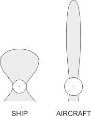
Typically, a ship’s propeller has between 4 and 7 blades [2]. By comparison with those of an aircraft propeller, the blades are short and stubby with a wide chord, in other words they have a low ‘aspect ratio’ (figure 7), and they may overlap close to the root. The wide chord ensures that each blade has a large surface area, which spreads the load and reduces the pressure differential between the front and back of the propeller disc, which can induce cavitation, a potentially destructive phenomenon that we’ll describe later.
Figure 8
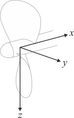
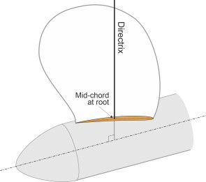
Each propeller blade has a beautiful but complex shape in three dimensions. It’s not easy to visualise, and we’ll need a frame of reference to help us. The primary frame of reference is similar to the one we’ll use later in Section M1115 to analyse the ship’s motion except that the origin lies within the propeller boss on the shaft axis, which we’ll assume is aligned horizontally, parallel to the ship’s direction of motion. The \(x\)-axis points forward in the direction of motion, the \(y\)-axis points to starboard at right-angles to the \(x\) axis and in the same horizontal plane, and the \(z\)-axis is vertically downwards (figure 8). Now let’s picture a typical propeller within this frame of reference: we’ll rotate the shaft until one of the blades is aligned vertically upwards, and hold it firmly in position. What does ‘vertically upwards’ mean? The blade profile contains no straight lines or flat surfaces so we construct a directrix, a straight line perpendicular to the shaft axis that passes through the centre of the blade at the root where it merges with the propeller boss. By ‘centre’ we mean the mid-chord of the root cross-section located at the point ‘A’ in figure 9, and this point A will act as the key reference point for our description of the propeller geometry. Also springing from this point is the median line of the propeller blade, the line that joins all the mid-chord locations along the length of the blade from root to tip (note that this is not standard terminology: propeller manufacturers have their own technical vocabulary as described in [6]).
Figure 9
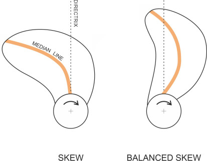
To produce maximum thrust with minimum drag, the cross-section of each blade is shaped like the cross-section of an aircraft wing (figure 10). As explained in Section F1513, this aerofoil cross-section lowers the pressure within the fluid passing over the forward face of the blade, and raises the pressure on the aft face. The reduced pressure over the forward face is responsible for most of the thrust. As you might expect, the face of each blade is set at an angle to the plane of the disk. The angle is largest at the root, and decreases steadily with radius in order to maintain a roughly constant angle of attack throughout (figure 11). So how to summarise the angle of the blade in terms of a single parameter? As described in Section F1518, the simplest method is to use the pitch\(P\) - the distance the propeller would move forward in one revolution if embedded in a pliable material that allows the blade to cut through it like butter [32]. There are several other features of the blade geometry that specialists find useful. We’ll mention just two: skew and rake. Let’s return for a moment to the propeller on Brunel’s Great Britain shown earlier in figure 5. Viewed from astern, the blades are arranged like the spokes of a cartwheel: they are (a) straight and (b) aligned radially. By contrast, modern propellers almost always have some skew: the median line of each blade (the line that divides the blade area into two equal parts) is curved in an elegant spiral which, close to the tip, trails behind the direction of rotation so that the blade cuts into the fluid in the same way as a swept aircraft wing (figure 12). This helps to even out variations in the lift force as each blade passes close to the hull and thereby reduces vibration [2] [31] [34]. However, the fluid pressure acting on a ‘trailing’ blade applies a torsional load around the propeller reference line at the blade root, and to counter this, the designer may angle the median line in the opposite direction close to the root, like a forward-swept wing. The effect is to balance the leading and trailing areas, an effect referred to as a ‘balanced skew’ [6].
Figure 10
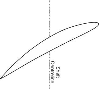
Figure 11
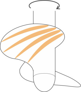
Figure 12
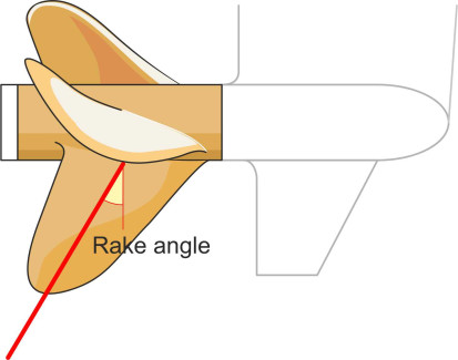
Finally, the blades are sometimes raked aft at an angle to the propeller shaft (figure 13). This may reduce vibration a little more by increasing the clearance between the blade tips and the hull, and it also evens out the impact of asymmetry in the hull wake [31]. You may have noticed from figure 12 that skew and rake are not independent features: a skewed blade must necessarily project aft of the propeller disc to produce the effect of rake even though the blade reference line is perpendicular to the shaft axis.
Figure 13
Manufacture
I mentioned earlier that a ship’s propeller is small, but it’s only ‘small’ in relation to the size of the hull. The propeller of a large container vessel like the Emma Maersk is nearly ten metres in diameter and weighs 131 tonnes. A propeller of this size is usually supplied by a specialist company, tailored to the client’s specification, with a design based on model tests and computer analysis; nowadays, there are computer packages capable of simulating the fluid flow over the blades and estimating the torque and thrust at any given rpm. For smaller vessels, the supplier may recommend an ‘off-the-shelf’ model from a standard range whose performance has been tested on other ships over a period of many years. The blade surfaces are shaped to produce the maximum thrust with the minimum amount of energy wasted in turbulence. Many of the standard cross-sectional profiles were originally adapted from aerofoil sections developed during the 1930s by the US National Advisory Committee for Aeronautics (later NASA).
If you’re familiar with the way materials behave, you’ll know that a metal will break more readily if you bend it first one way, then the other, many hundreds of times: its ‘fatigue strength’ when subjected to cyclic load reversals is different from its ‘yield strength’ under a steady or slowly changing load. In service, a ship’s propeller rotates typically at 120 rpm, and if it operates for 250 days per year, each blade will undergo roughly 1 000 000 000 stress cycles during its 20-year life [15], so for a ship’s propeller, it’s the fatigue strength that counts [17]. The fatigue strength is determined by what happens close to the blade surface, where the stress reversals pump energy into any cracks or fissures in the crystalline structure. A smooth surface will resist stress better than a rough one, because stresses tend to concentrate at the base of any indentation (figure 14). Surface indentations can arise through scratches or cavitation, assisted by corrosion as salt water eats into the crystal structure and further reduces the fatigue strength of the material. Assisted in this way, stress reversals can open up a small surface imperfection to form a crack that propagates without warning into a full-blown fatigue fracture [14].
Figure 14
This is why propellers are made from tough materials. The word ‘tough’ is important here: you might expect a blade to be hard like a diamond, but hard materials tend to shatter under the impact of a sudden blow. The material that can best withstand these punishing conditions is bronze. Under extreme stress, it yields a little but doesn’t easily break. We usually think of bronze as an alloy of copper and tin first discovered around five thousand years ago, the material from which the statues that adorn our city squares are made. By today’s standards, it’s not particularly hard, but it stands up well to the propeller environment and loading regime. Most modern propellers are nickel-aluminium bronze, which in addition to copper and tin contains around 5 - 10\(\%\) of aluminium, together with a small amount of nickel. It has largely replaced other materials because it resists corrosion, is less readily colonised by algae and other marine organisms, and it stands up better than stainless steel to cavitation [16].
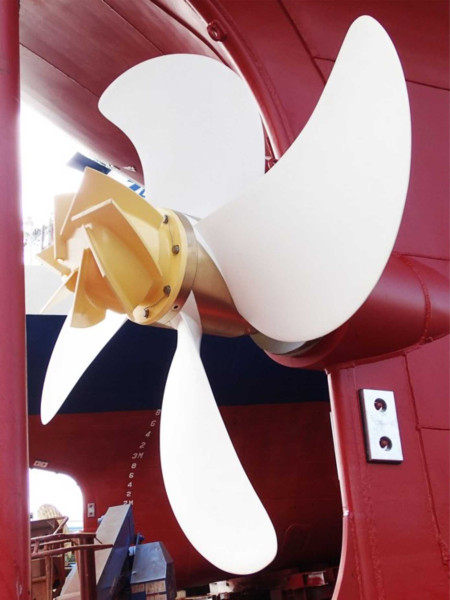
As an alternative to bronze for small craft, carbon composite propellers work well [16], and they have been fitted to submarines because they vibrate less freely than metal alloys, and the noise they make under water is less easy to detect. More recently, their use has spread to larger vessels: a carbon composite propeller for a container ship might weigh 50 tonnes compared with 130 tonnes for the equivalent bronze casting, and the reduced weight means the vessel can carry more cargo. Figure 15 shows a typical example. The small fins on the propeller boss are a recent innovation: called ‘propeller boss cap fins’ or PBCFs, they rotate at the same speed as the shaft, their purpose being to increase thrust by interrupting the vortices generated by the blade roots and preventing them rolling up into a hub vortex that would otherwise dissipate energy via the slipstream.
Figure 15
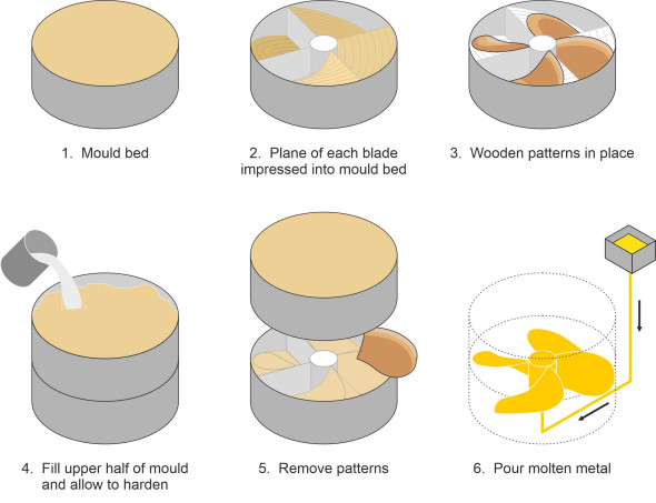
Propellers for commercial ships are mostly ‘one-off’ items tailored to a particular specification. If you think about it, a ship’s propeller can weigh anything up to 200 tonnes and there aren’t many foundries in the world that can create anything that size in one piece. A conventional propeller is created by pouring molten bronze into a mould and it has to be done (a) quickly before the liquid solidifies and (b) carefully so that the molten surface doesn’t oxidise in contact with the air - any particles of slag carried into the substrate through turbulent motion can weaken the crystal structure. You’ll find a good description of the traditional process of propeller casting in [18], and what follows is an abbreviated version. As shown in figure 16, the mould is usually made in two halves with the propeller axis aligned vertically and the blades arranged face-down (the ‘face’ is actually the rear of the propeller disc). The lower half of the mould, the ‘bed’, is created within a circular frame resting on a reinforced floor. It is filled with washed silica sand mixed with Portland cement and water. The basic form of each blade is impressed into the bed using a ‘striking board’ that pivots around the shaft centreline and traces out a helical path, scraping out excess material. Then a pattern is placed on the bed, one for each blade, and the upper half of the mould poured on top. When the cement is dry the upper half is lifted off, the patterns removed, and the upper half replaced again to leave blade-shaped cavities inside the mould.
Figure 16
The pouring operation follows a sequence designed to accommodate shrinkage as the metal cools, and to control variations in the crystal grain size and strength throughout the blade cross-section. Molten metal is poured into one or more ‘runner boxes’ arranged around the perimeter at a controlled rate (for a large propeller it’s quite fast, maybe 8 tonnes per minute). From there it is carried through pipes into the mould cavities not, as you might expect, at the top, but at the bottom, so the liquid surface rises smoothly inside the cavities with minimal turbulence. The casting takes several days (maybe two whole weeks) to cool. Then the mould is broken away and the propeller suspended with its axis horizontal for boring. Afterwards, the propeller surface is finished to an accurate profile using numerically controlled machines running on gantries.
Propeller installations
During the golden age of transatlantic sea travel, it was common for a ship to have more than one propeller. A passenger liner or a warship, which required enormous power to maintain a cruising speed of 30 knots, might boast four, two on either side. Today, most vessels manage with one or two. However, all have one thing in common: unlike aircraft propellers, ships’ propellers are mounted at the stern.
Where and how many?
There seem to be three reasons for this. First, a bow propeller is exposed to damage if the ship hits an obstruction under the water or runs aground. A broken propeller will render a ship helpless, but if the propeller is mounted at the stern, it is likely to remain intact during a collision so that the ship can survive and limp into port for repairs. Second, for reasons we’ll set out in Section M0505, a ship’s rudder is normally located at the stern, and with a front-mounted propeller, it cannot rely on the slipstream to boost the rudder steering forces. Third, a propeller mounted on the bow would project fluid onto the bow plating, where it would generate friction and waste energy as well as causing vibration. Hence in almost all cases, a ship’s rudder is mounted at the stern. However, even a stern-mounted propeller won’t last very long if the blades stick out on either side of the hull, or project below the keel. So the blades have to lie within the hull cross-section where they are protected from accidental impact with a quayside or a shallow river bed.
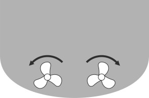
So how many propellers does a ship need? Broadly, there are three alternatives: (a) a single large propeller, and (b) two smaller ones, or (c) more than two. Today, cargo ships account for the greater proportion of traffic, and tankers and container ships are usually powered by a single screw because with only one drive shaft, the hull structure is simpler and cheaper to build, and a single screw is widely observed to be more efficient. However, two propellers are often preferred for larger ships such as passenger liners, partly because the second propeller provides insurance if one fails, partly because two smaller screws allow for greater clearance between the blades and hull than a single large one, and partly because two propellers enable the crew to manoeuvre more easily at low speed. Recall that a ship can’t steer unless it is moving sufficiently fast for the rudder to generate sideways ‘lift’, so it’s difficult to manoeuvre a vessel in a restricted space such as a port or harbour. If the propellers can be engaged or disengaged independently, it’s possible to swing a craft round by running one propeller in the forward direction and the other astern as shown in figure 17, which applies a turning moment to the hull. (Ships are not the only vehicles that can steer using asymmetric thrust in this way. You can probably think of several others. My father once owned an old-fashioned motorbike and sidecar, whose thrust derived from the rear wheel of the bike, which on a British machine, was located on the right-hand side of the vehicle. He explained that if he opened the throttle suddenly, it would ‘turn sharp left’.) Twin propellers usually run in opposite directions, turning outwards as shown in figure 18. The reason is that any ship’s propeller produces a transverse thrust called the ‘paddlewheel effect’, which we’ll describe shortly. The paddlewheel effect can be exploited to help steer a vessel with two propellers, but as will be seen in Section M0505, only if they turn outwards.
Figure 17
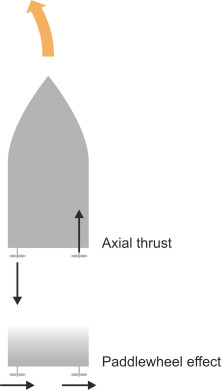
Figure 18
Interaction with the hull
The thrust produce by a ship’s propeller is affected by the shape of the hull to which it is attached, which influences the pattern of flow through the propeller blades. To predict the performance of the hull-propeller combination, the designer will analyse or simulate the ‘wake field’ in some detail, as described for example in [8]. Here, we won’t go into detail, but try to describe the process in qualitative terms.
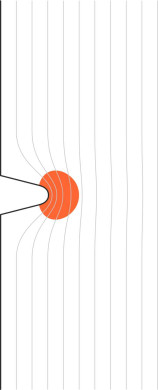
A ship’s propeller is located behind the hull and in almost all cases lies entirely within the hull cross-section. Water in the vessel’s path must divide around the bow and curve inwards at the stern before being drawn into the propeller stream tube, and the fluid in the boundary layer loses some of its relative velocity to friction with the hull surface. Hence any given propeller will work differently when installed on different ships, and differently again when tested in a laboratory with no hull present. As explained in Section F1518, this last condition is called the ‘open water’ condition, and it forms the starting point for assessing any new propeller design or for comparing alternative propellers that might be candidates for installation on a particular vessel.
Although common sense suggests that the hull gets in the way of the approaching fluid, this does not necessarily impede the propeller’s performance: in fact, locating the ship’s propeller in the hull wake can be an advantage. The thrust it develops does not depend on the fluid velocity upstream or downstream, only on the change in velocity of the water passing through the actuator disc. With the propeller located behind the hull, the water is slowed down by friction as it moves along the hull plating, and it arrives at a lower speed than it would do otherwise. After accelerating through the required velocity increment, it departs in the slipstream at a lower velocity than it would in the open water condition. It therefore wastes less energy in the slipstream and the process is more efficient.
On the other hand, the fluid pressure in the stream tube falls as it approaches the actuator disc, and this pressure fall is transmitted to the plating on the stern, which effectively increases the hull resistance. So there are two opposing mechanisms, one favourable, the other not, and the outcome depends on the balance between the two. In certain circumstances there can be a net benefit [24], and one authority cites delayed separation and reduced drag on the hull as an additional factor [30], see also [9] [22].
Eccentric thrust
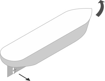
If a propeller revolves clockwise when viewed from astern, it is said to be right-handed (figure 19). In practice most single-propeller installations are right-handed, and this seems to have been settled by tradition. Whether right-handed or left-handed, there seems no obvious reason why the mean thrust generated by the blades shouldn’t be aligned centrally with the hub. However, the boundary layer close to the hull plating distorts the fluid flow as it approaches the propeller, and this has two consequences:
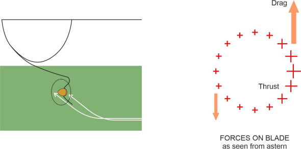
- Fluid particles that pass through the upper half of the disk do so more slowly than those entering the lower half [27]. They meet each blade at a higher angle of attack, and generate more thrust and more drag. As a result, the thrust acting on each blade rises and falls during each revolution, peaking at the 12 o’clock position in the upper half of the propeller disk. And for a right-handed propeller, the drag force also peaks in this position (figure 20).
- Since the underside of the hull slopes upwards at the stern, the incoming fluid does not arrive at an angle perpendicular to the propeller disc. This causes further variations in the angle of attack for each blade throughout its orbit, which for a right-handed propeller, is greatest on the starboard side. This produces another momentary peak in thrust and drag as the blade passes the 3 o’clock position viewed from astern (figure 21).
For a ship with a single propeller, these two effects can cause the thrust on each blade to vary by a factor of 3 or more around its 360 degree orbit [14]. The resulting vibration is a matter that we’ll take up later. For the moment, we’ll note that when averaged over the disc as a whole, there is a shift in the line of action of the propeller thrust upwards and to starboard of the shaft centreline, together with a net transverse drag to port. Both affect the ship’s steering. In principle, the shift in the thrust centreline biases the steering to port, while the tranverse drag biases the steering to starboard, so the two effects act in opposite directions. Both, however, are relatively small in practice compared with another effect, which is produced by the interaction of the propeller slipstream with the rudder.
Figure 19
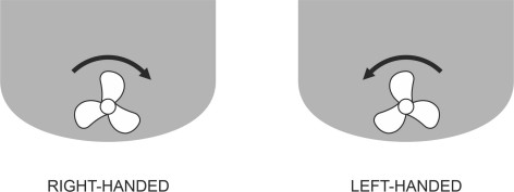
Figure 20
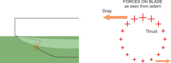
Figure 21
The paddlewheel effect
A conventional propeller not only drives the ship forwards, but tends to swing it to one side. The phenomenon is sometimes called the ‘paddlewheel effect’ [1]. Without any corrective action from the helmsman, a right-handed propeller will swing the hull to port, whereas a left-handed propeller will swing it to starboard, and the explanation is complicated. The propeller slipstream has a rotational component: as the propeller ‘screws’ its way through the water, it drags the fluid particles into a whirling motion as well as drawing them aft. This whirling motion makes no contribution to propelling the ship but it does affect the steering. Above the shaft centreline, the particles in the ship’s wake approach the rudder from the port side, while below the centreline, they approach from the starboard side (figure 22). Since the thrust is biased towards the upper half of the disk, the former predominates. Hence with the rudder centred on the ‘ahead’ position, the propeller slipstream induces a net thrust on the rudder towards the starboard side, which causes the hull to veer to port (figure 23). Presumably if left to its own devices, the ship will travel in a circle, anti-clockwise. Similarly, a ship with a left-handed propeller will veer to starboard [27] and circle clockwise.
Figure 22
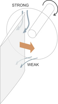
Figure 23
All the above applies to a single-screw ship whose rudder is located within the propeller slipstream. But what about a twin-screw vessel? Many ships with twin screws have a single rudder mounted centrally on the hull. Normally the screws rotate in opposite directions so any transverse forces generated by the two propellers cancel one another out. But when one of the propellers is put into reverse, the ship will exhibit a significant paddlewheel effect even though the slipstream of neither propeller acts directly on the rudder surface. The explanation seems to lie in the fact that when either the port or starboard propeller is operating in reverse, it changes the ship’s wake field, the result being a net transverse pressure on the hull flank [21].
Noise and vibration
When it flies overhead, people usually notice a propeller-driven aircraft because the propeller makes a characteristic thrumming noise. A ship’s propeller is noisy too, but when watching from the shore, we don’t notice because the pressure pulses are contained beneath the water surface. They are created in three different ways. We have already mentioned one of them: the propeller blade meets varying conditions as it spins around the shaft so that the lift and thrust forces acting on each blade rise and fall during each revolution. The second arises from the abrupt collapse of bubbles created on the low-pressure side of each blade, a process called cavitation. The third arises from the propeller blades themselves, which can resonate at audible frequencies. We’ll explain these last two processes before going on to review the wider impact of propeller noise on the ocean environment.
Cavitation
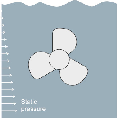
When rotating above a certain speed, the behaviour of a ship’s propeller enters a new dimension. Conditions at the interface between the blades and the fluid around them become more extreme, with large variations in the pressure exerted on different parts of the blade surface. The critical parts are not as you might expect the areas under high pressure, but those under low pressure. When the pressure falls below a critical value, bubbles of gas called cavities begin to form (figure 24). The cavities arise in two different ways. First, when exposed to the atmosphere, seawater absorbs gas molecules. Close to the surface, it contains up to about half a percent by weight of oxygen [7], and the oxygen re-emerges from solution when the pressure falls [28] [35]. Second, when the pressure falls further, the water itself can turn into a gas. It happens whenever you boil a kettle. The fluid inside changes from liquid water to bubbles of steam that rise energetically to the surface. But you don’t need heat to produce water vapour. The temperature at which boiling takes place depends on pressure, and when the pressure falls below the vapour pressure, water will boil at the same temperature as its surroundings. The result is bubbles of water vapour in addition to those of the emerging oxygen. To complicate matters further, the vapour pressure itself varies with ambient temperature [3], so it’s not easy to predict when and where the bubbles will form.
Figure 24
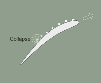
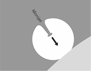
We have already mentioned this vaporisation process in Section M1716 in connection with hydrofoils. It can occur in any machine that creates pressure variations in a liquid, for example a rocket fuel pump or the human heart. It is called cavitation. It limits the performance of the system, and it may be destructive. You can imagine what happens when a bubble moves away from the low-pressure zone in which it was created. The vapour can no longer be sustained and the bubble collapses. The surrounding water rushes in, and since it’s virtually incompressible, there is nothing to soften the impact, which produces a shock wave rebounding into the surrounding fluid in which the pressure may rise by as much as 4000 atmospheres [10]. Even more extraordinary is what happens when the bubble collapses near a solid wall such as the surface of a propeller blade. We are speaking of events on a microscopic scale that are difficult to observe, but the shape of the bubble distorts as it contracts. The part furthest from the wall contracts more quickly and forms a microjet directed at the wall (figure 25). The microjet is thought to travel at up to 1000 m/s [11] but this remains to be confirmed by experiment [36]. Not surprisingly, cavitation can cause pitting and erosion of the blade surface together with increased risk of fatigue fracture [26]. And collectively, the shock waves produce noise and vibration when they impact the hull.
Figure 25
So where exactly do the bubbles form, and where do they collapse? Initially, a cavitation bubble needs some form of nucleus around which it can develop. In seawater, a typical nucleus consists of a minute bubble of gas trapped within an envelope of organic molecules or other detritus. The nucleus can either (a) be moving through the propeller disc, carried along by the surrounding fluid, or (b) rest embedded in a crevice on a blade surface. Moving bubbles arise within the low-pressure region close to the suction side of each blade as shown earlier in figure 24, and they also form within the low-pressure core of the vortex trailing from the blade tip. But these moving bubbles don’t occur in equal numbers at all angles around the propeller shaft. As figure 26 shows, the static pressure is lowest at the top of the propeller disk, so more bubbles are generated as the blade passes through the 12 o’clock position than when it passes through the 6 o’clock position at the bottom. At the same time, ‘embedded’ bubbles grow from nuclei attached to the blade surface close to the leading edge. They remain attached to the blade and at higher speeds will grow and coalesce into a continuous sheet [12] [35]. This effectively limits the suction that the blade can develop and therefore the total thrust.
Figure 26
Of the different kinds of cavitation, some are more of a nuisance than others. In practice, many ships’ propellers cavitate at normal cruising speed, usually producing a helical trail of bubbles from each blade tip. Ship owners tolerate such cavitation because the collapse of the bubbles takes place some distance away from the propeller itself where the percussive pressure waves emanating from a bubble collapse can’t damage the blade surfaces. However, a further increase in speed leads to more severe forms of cavitation that impair the propeller’s efficiency, and designers usually try to avoid them. There are several ways to do this. The first is to locate the propeller well below the water surface. The deeper it lies, the higher the static water pressure and the faster the propeller can rotate before the water pressure on the suction face of each blade falls below the vapour pressure. But there’s not much scope for manoeuvre because the blades mustn’t project below the bottom of the hull where they risk being damaged. A second alternative is to make the propeller larger, because any increase in the diameter of the propeller disc reduces the loading per unit area of blade and therefore reduces the extremes of pressure variation [33]. Thirdly, one can ‘skew’ the blades. As we remarked earlier, a skewed blade is the geometrical equivalent of the swept wing of a high-speed aircraft (see figure 12), and it raises the critical speed at which cavitation begins. For a cargo ship with a single propeller, a skew of 60º can increase the maximum (cavitation-free) speed by 3 knots [35]. Finally, for high-speed craft, a radically different solution is available: propellers whose geometry is specifically designed to accommodate cavitation, an idea to which we’ll return in Section M1405.
The singing propeller
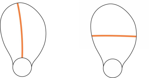
Earlier in Section R1610 we saw how a railway wheel will ‘ring’ like a church bell when jolted or struck with a hammer. A propeller blade will do the same, and as with a railway wheel, the vibrations follow a characteristic pattern or mode. For any given mode, the area of the plate can be divided into zones, each of which oscillates in time with its neighbours but with opposite phase. The zones are bounded by nodal lines where the amplitude is zero. For a ship’s propeller, the patterns can be quite complex [19]. Figure 27 shows diagrammatically two of the simpler modes. Of course, a marine propeller is immersed in water, which tends to damp the vibration and lower the frequency. Nevertheless, from time to time a propeller will sing. The noise varies from a deep grunt for a large propeller to a piercing warble for a small one. The cause seems likely to be vortices that appear on the suction side of each blade. They occur at the point where the boundary layer separates from the blade surface, and they stimulate resonant frequencies associated with higher vibration modes. The phenomenon doesn’t occur very often and is difficult to predict, but it is intensely disturbing for passengers and crew, and the owner will usually arrange for the vessel to go into dry dock as soon as possible to have the propeller modified. Apparently there is a simple cure, which is to chamfer the trailing edge of the blade [20].
Figure 27
The effects of noise and vibration
It seems there are at least three different ways in which a propeller can create noise or vibration: eccentric loading, cavitation, and resonance. So let’s round off by asking how the resulting disturbances are propagated and whether they have a significant impact. It helps to divide the disturbances into two categories: those created within the hull structure, and those transmitted into the wider ocean environment.
In fact, noise and vibration can enter the hull structure via two different routes. The first is through the propeller shaft. Vibration increases the rate of wear on the shaft bearings, and over its twenty-year lifetime, the resulting stress variations may damage the propeller blades themselves through metal fatigue [15]. The second route is through the water: the pressure pulses are generated only a short distance below the hull plating at the stern, which in turn passes on the disturbance to the ship’s structural framework. The effects on the passengers and crew can be a major problem on ships, one that we’ll take up separately in Section M0118.
Other noise and vibration emissions spread out in the ship’s wake. They travel a long way through seawater: if its propeller is cavitating, whales can hear a supertanker the day before it arrives. Author and journalist Rose George has pieced together an absorbing account of what has been happening to mammals in the world’s oceans during the last few decades [25]. Many are killed outright in collisions with ships, but many more are affected by propeller noise, which in some areas now dominates the acoustic environment. Sea mammals - and presumably quite a few fish - use sound to map their surroundings and communicate. In quiet water, a right whale can hear another right whale 10 miles away, and many species rely on echo-location for hunting and for navigating along the coastline. But today, aquatic mammals are experiencing noise levels that are roughly equivalent to the ones experienced by humans living next to an international airport. In consequence, their acoustic range has shrunk, or as George puts it bluntly, their ability to find food and a mate has been decimated: whales that can’t communicate can’t breed. Further details of ambient noise levels, the noise signatures of modern vessels, and the calls of sea mammals can be found in [13], and in the material cited under ‘Further reading’ at the end of this Section.
Conclusion
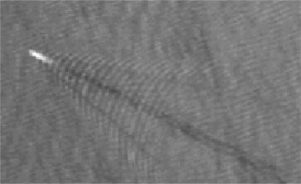
Cargo ships form the backbone of the world’s transport system. They use low-grade diesel oil (roughly 7 million tonnes per annum), their exhaust emissions account for 3 – 4\(\%\) of all greenhouse gases, and for the reasons just explained, their noise emissions pose a risk to the marine ecology. A key issue hinges on the way the propulsive force is channelled through the propeller. A propeller is the best way we know of moving a large vessel, but it’s not 100\(\%\) efficient and the propeller injects a great deal of energy into the sea. As observed from an orbiting satellite, the turbulent plume extends for a considerable distance in the ship’s wake (figure 28). Only recently have the ecological consequences become clear. Finding ways to reduce turbulence, noise and vibration in the propeller slipstream is perhaps one of the most difficult problems facing designers today. In Section F1518 we’ll look more closely at the energy losses, and in Section M1405 we’ll consider more advanced or specialised forms of propeller that might use less fuel.
Figure 28
Acknowledgements
Photo on opening page: Propellers on the RMS Olympic, sister ship of the Titanic, in Thompson dry dock at the Harland & Wolff Shipyard in 1911, Public domain via Wikimedia Commons, https://commons.wikimedia.org/wiki/File:RMS_Olympic%27s_propellers.jpg (accessed 16 May 2021).
Figure 05: The propeller on the Great Britain, photo by Derbyshire Dale via Creative Commons at https://en.wikipedia.org/wiki/Propeller#/media/File:Great_Britain_propeller_and_rudder_wideshot.jpg (accessed 11 February 2016).
Figure 15: Nakashima Carbon Fibre Reinforced Plastic (CFRP) propeller, posted at https://www.nakashima.co.jp/eng/product/cfrp.html, accessed 16 May 2021.
Figure 28: Satellite photo appearing in ERCIM (European Research Consortium for Informatics and Mathematics) NEWS 108 January 2017, Special theme: ‘Processing satellite imagery to detect and identify non-collaborative vessels’ by Marco Reggiannini and Marco Righi (ISTI-CNR), https://ercim-news.ercim.eu/en108/special/processing-satellite-imagery-to-detect-and-identify-non-collaborative-vessels, copyright Marco Reggiannini and Marco Righi and posted under Creative Commons Attribution 4.0 International License (CC-BY), accessed 20 November 2019.