C.1602
Pavement structure
The path followed by a railway train is determined by the geometry of the track, and the wheel loads never deviate more than a few millimetres from the centre of each rail. But road vehicles can wander from one side of the road to the other, overtaking, steering round obstacles and occasionally parking at the kerb. Hence the road surface must be continuous over a relatively large area, and strong enough to bear the wheel loads anywhere across the width swept out by vehicles of different shapes and sizes. The only way to do this is to spread a lot of material across the ground surface in the form of a thick, hard skin. The function of the skin is to reduce the stresses under each tyre to a manageable level before they reach the ground beneath: a strong pavement spreads the load over a larger area than a weak one and enables the passage of heavy lorries that would otherwise sink into a weak soil. Of course the road has other purposes too: mainly to provide grip for vehicle tyres together with a smooth surface to ride on. These two aspects are dealt with separately in Section C1603.
Roads are built largely from natural materials dug out of the ground. Vast amounts are consumed in this way, much greater than those needed for a railway line carrying an equivalent amount of traffic. The total area of public road in Britain is about 3,300 square kilometres. Assuming an average depth of 0.2 m and density of 1500 kg per cubic metre, the total weight of prepared material comes to one thousand million tonnes, more than thirty tonnes for every vehicle in the land.
How a pavement works
Any structure that forms a surface over which vehicles or pedestrians can move is technically known as a pavement. In the UK, the part over which vehicles move is called the carriageway, and the part over which pedestrians move, the footway. The ground surface on which it is laid is known as the grade, and the material beneath the subgrade. Ultimately, it is the subgrade that supports the weight of passing vehicles, and in this sense, the pavement doesn’t actually carry loads at all, at least not in the same way as a bridge or a skyscraper. When a bridge fails, it is liable to collapse in a spectacular fashion, whereas the failure of a pavement is gradual because it can’t fall down. But it can disintegrate, and the damage accumulates with every passing vehicle.
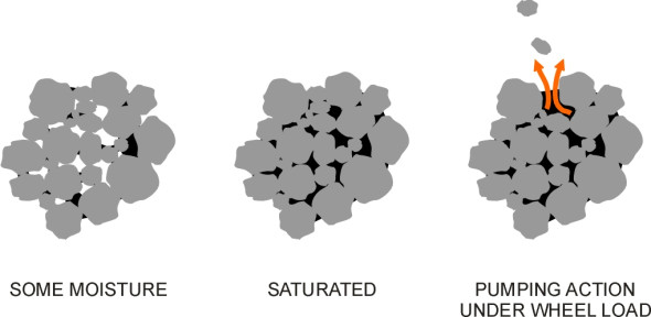
In fact, most natural soils can bear a considerable weight provided the weight is distributed evenly over a sufficient area and the soil is kept dry so any load is transmitted directly from one granule to the next. The surface should be waterproof, and the edges well drained so that water cannot percolate beneath. The reason is that once it penetrates the pavement material or the soil below, water has a destructive effect because it is virtually incompressible. When soil is heavily compacted, there are not many spaces left between the granules and it doesn’t take much water to fill them. When they’re full, the load no longer passes through the solid matter but (at least partially) through the liquid, whose pressure rises and relieves the contact forces among the granules. Since they no longer press against one another, the granules cannot interlock and instead, behave more like ball bearings in a bath of oil. Worse, a heavy vehicle passing overhead will squeeze the material and cause water to be ejected under pressure. As it rushes out of the gaps it will carry the finer particles with it allowing the granules to move more freely. Saturated soil quickly becomes a soggy mass (figure 1).
Figure 1
Wheel loads
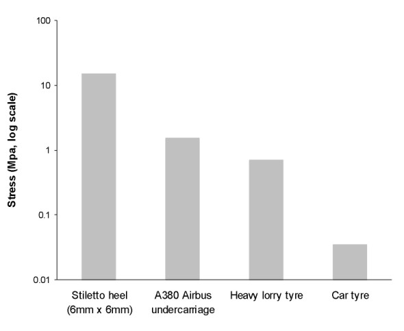
The pressure exerted on a pavement surface varies widely according to who or what is standing on it (figure 2). In the case of a family saloon car, the tyres exert a pressure of about 35 kPa, compared with 1500 kPa under the tyre of an Airbus A380 undercarriage, about 40 times as much. On a footway, the stress under the 6 mm x 6 mm heel of a stiletto shoe peaks at around 15000 kPa, ten times as much again [13]. But for the highway engineer, the greatest challenge is the heavy lorry. The stress is less than the stress under a stiletto heel, but the load is greater. In most countries, the maximum permitted load for any one axle is around 10 tonnes, and since the axle usually rests on four wheels we can see that the maximum load passing through a single contact patch is 2.5 tonnes. The tyre will exert a pressure of around 700 kPa or 700 kilonewtons per square metre at the road surface [13] and somehow this must be reduced to a value that lies within the bearing capacity of the soil beneath. The bearing capacity of gravel is around 600 kPa, that of sand about half as much, and clay half as much again [15]. On this basis, gravel is nearly ‘strong’ enough to carry heavy lorries: the problem is not so much to reduce the pressure but to stabilise the surface so the individual chippings can’t move. Clay is a different matter. Here, the pavement must effectively reduce the stress by a factor of at least four.
Figure 2
The cone of stress
When you place a heavy weight on the ground, the load spreads out beneath the surface so that immediately underneath, the stress decreases with increasing depth. But no matter how far down you go, it never vanishes entirely. Imagine the earth sliced by horizontal cuts like an enormous loaf of bread standing on end, and concentrate on the cut whose plane is located say one kilometre below the surface. In principle, a lorry travelling along a motorway is detectable even at this level, in the form of a very small increase in stress spread over a very large area. The plane extends indefinitely in all directions, but we can imagine it broken down into small squares each acted on by a small load increment. If we add together all the load increments, the answer will be equal to the weight of the vehicle at the surface.
Surprisingly perhaps, the weight has an effect at a considerable horizontal distance away from the contact patch too. Imagine an agricultural tractor parked in a field and consider the nearside rear wheel say. Now in your imagination walk 10 paces away from the wheel in any given direction, and choose a point on the ground surface. There’ll be no sign of any extra pressure in the soil, because at the surface itself, the vertical stress increment is zero. But immediately below the surface, things change. A millimetre down, the stress increment will be microscopically small, but it is real, and as we shall see, it increases with depth up to a maximum value and then declines. Everywhere within the earth’s sphere, the extra stress produced by the tractor wheel is non-zero at any finite depth, and in this sense, the tyre has a wide sphere of influence. You cannot draw a boundary that defines where the effects of the wheel load end.
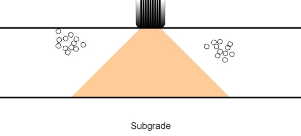
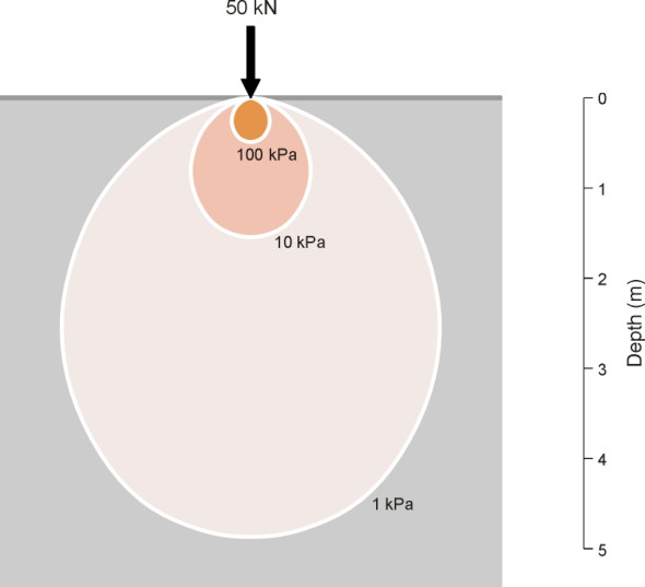
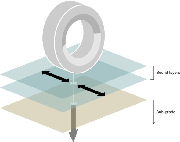
With this in mind, let’s return to the key question: how quickly does the load spread out under the tyre of a road-going vehicle? This is vital because it determines how thick (and therefore how expensive) the pavement structure must be in order to reduce the stress to a value within the bearing capacity of the underlying soil. The standard model in highway engineering textbooks depicts the process as a ‘cone of stress’ (figure 3) that spreads out laterally at an angle of about 45\(^\circ\) [22]. This is a useful simplification but can it be justified? Why should the contours should follow a conical pattern, and why should the angle of the cone should be 45\(^\circ\)?
Figure 3
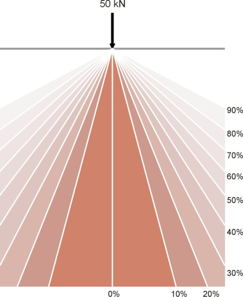
Denote the wheel load by \(P\), and imagine once more a horizontal plane within the earth some distance below the contact patch. We’ll draw on it a series of concentric circles. Take any given circle and divide its area into small parts. If we know the vertical stress on each part (we’ll propose a formula shortly), we can multiply the stress by the area to get a load, this being the part of the wheel load that is channelled through the area in question. For the circle as a whole we calculate the total load passing within its perimeter by summing the individual loads, in other words we integrate the stress with respect to area. Suppose the result comes to 0.5\(P\). This tells us that at the depth in question, half of the wheel load passes through the circle and half outside. In the language used by statisticians, the circle represents a 50% quantile. What about the other circles we have drawn? Each circle represents a different quantile, with the 0% quantile as a dot in the centre, and circles of increasing size representing greater proportions of the load.
Figure 4
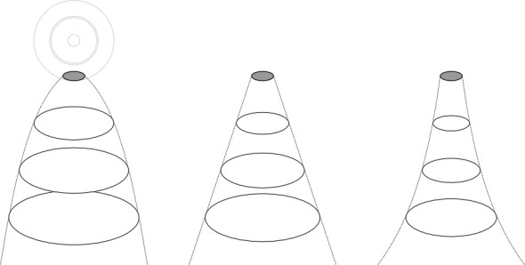
We can now move to a greater depth to repeat the exercise, and draw a similar set of circles. Each quantile will have a larger diameter than previously because the load will be spread over a larger area. If we continue to do this we see that any particular quantile will grow in diameter with increasing depth. It now makes sense to examine how rapidly the growth takes place for any particular quantile – say the 50% quantile. Is the growth linear, with the diameter exactly proportional to depth, or does it follow some other pattern? figure 4 shows some alternatives. To find the answer, we turn to some 19th century mathematics.
Stress distribution
Exactly how the stress decays underneath a wheel load is quite a difficult theoretical problem. It helps if the contact patch is shrunk to a single point, and the earth is regarded as a perfectly elastic, isotropic material that extends to infinity horizontally and vertically beneath a flat plane. It wasn’t until 1848 that Kelvin formulated the differential equations for stress under a point load under these assumptions, and only in 1885 did the French mathematician Boussinesq publish the solution [20]. If \(P\) is the wheel load, and \(E\) is the modulus of elasticity of the soil, then the vertical stress \(\sigma_{z}\) at a depth \(z\) below the surface and a horizontal distance \(r\) from the vertical load centreline is given by the formula
(1)
\[\begin{equation} \sigma_z \quad = \quad \frac{3 P z^3}{2 \pi R^5} \end{equation}\]where
(2)
\[\begin{equation} R^{2} \quad = \quad r^2 \; + \; z^2 \end{equation}\](Note that for present purposes we are counting a compressive load as positive, whereas structural engineers usually count tension as positive). Of course, a point load is physically impossible because it implies infinite stress, which no real material can withstand. But the formula gives values reasonably close to the true ones except in the immediate vicinity of the contact patch. Bearing this in mind, it is a straightforward task to plot lines of equal stress as shown in figure 5. What we are looking at is a cross-section of a series of 3-dimensional surfaces each shaped like an old-fashioned electric light bulb. Note that each bulb has exactly the same proportions but is scaled to a different size.
Figure 5
We can now return to our earlier notion of a load quantile. For a circle of radius \(r\) at depth \(z\), we can find the proportion \(p\) of the load concentrated within that circle by integrating the expression for the vertical stress in equation 1 with respect to radius over the range 0 to \(r\). It is not difficult to show that the proportion is given by
(3)
\[\begin{equation} p \quad = \quad 1\;\; - \;\; \frac{1}{\left( {1 + \frac{r^2}{z^2}} \right)^{\frac{3}{2}}} \end{equation}\]and by substituting any particular numerical value for \(p\) we can solve for \(r\) in terms of \(z\). For any given \(p\), the relationship turns out to be a straight line. Suppose, for example, we wanted to know the radius of the circle containing just two-thirds of the load. We put \(p\) = 0.667 and then we find
(4)
\[\begin{equation} r \quad = \quad z \sqrt {\frac{1}{(1 - p)^{2/3}} \;\; - \;\; 1} \quad = \quad z \sqrt {0.333^{-2/3} \; - \; 1} \quad = \quad 1.040z \end{equation}\]This is just a straight line at an angle of about 46\(^\circ{}\) to the vertical. It seems we have arrived at a general principle: under the assumptions as we’ve stated them, any given proportion of the load spreads out over an area whose radius increases linearly with increasing depth, and if we choose a value for p equal to about 0.67, the angle is very close to the model depicted by the 45-degree ‘cone of stress’. However, the thing that is spreading out is not a stress contour or boundary, but a quantile representing roughly two-thirds of the wheel load. Figure 6 shows the complete set of quantiles.
Figure 6
Pavement materials
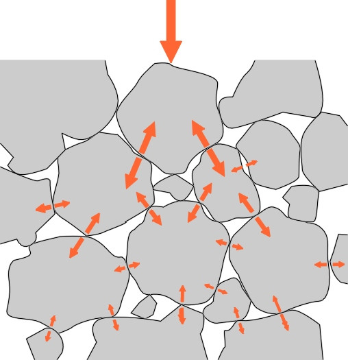
Even without anything to glue them together, it is not difficult to make a pavement from layers of stones with sharp corners that interlock under pressure so that any load applied to the surface spreads out progressively over a wider area as it passes downwards through the material (figure 7). A structure of this kind has for the last 150 years been the traditional method for supporting railway tracks, where the stones are all roughly the same size and the surface has an open texture. But for roads, where the surface is churned up by moving vehicle wheels, this would quickly disintegrate, and instead, the stones are ‘well graded’ with a mixture of many different sizes. Before the road is opened to traffic, the stones are compacted so they form a dense interlocking mass whose surface resists water penetration and rutting.
Figure 7
Unbound roads
Early roads in Europe, and existing roads in many countries today, were built mostly along these lines, i.e., made from smallish stones rammed into prepared ground. It sounds primitive, but such pavements were very effective in the days when the wheels of horse-drawn wagons were shod with iron rims. In fact they became stronger with use because the metal rims tended to grind off particles of grit from the surface granules. These particles fell into the gaps and formed a kind of dry cement bedding that held the larger granules in position and resisted penetration by rainwater.
In the UK, one of the first engineers successfully to develop ‘unbound’ road construction of the type just described was John Loudon McAdam (1756 – 1836). For McAdam, the challenge was not just to build durable roads, but to build them economically. By dispensing with foundations, but at the same time paying close attention to drainage together with the placement of carefully chosen materials, McAdam could produce more miles of serviceable road within a given budget than his competitors.
Nowadays unbound roads are still in use throughout the world. They would be more common in the industrialised countries of Western Europe and the USA were it not for the arrival of the motor car at the end of the nineteenth century. The problem was not size or weight – cars are not particularly heavy – but the fact that their rubber tyres sucked out the fine particles that made the surface waterproof, leaving behind a plume of dust that choked pedestrians, coated nearby buildings, obscured visibility for other drivers, and clogged the carburettor and cooling system of the vehicle itself [6]. It was the discovery that stones could be effectively glued together with coal tar that made the automobile running on pneumatic tyres practicable.
Today, many different combinations of material are used in road construction and we won’t try to describe them all. However, we shall mention some of the more important ones before going on to consider how they stand up to wear. For more information, readers may want to refer to the design manuals that are currently being updated by the American Association of State Highway and Transportation Officials (AASHTO) [4], or alternatively the UK Highways Agency Design Manual for Roads and Bridges [24], which can be down-loaded from the internet site listed at the end of this section.
Bound macadam
A bound macadam is a material in which before they are laid, the stones are coated with bitumen or cement to bind them together. As with non-bound road materials, coated macadams rely for their strength on aggregate interlock(figure 7). The stones press directly against one another, and the bitumen or cement is required only to keep them in place. Hence the mixture contains air voids, and while it can easily be compacted it is pervious to water [23]. In Britain, the first mix of this kind was called tar macadam, often shortened to ‘tarmac’ (the proper term is asphaltic concrete in line with US and European nomenclature). In 1901, Edgar Purnell Hooley, County Surveyor of Nottinghamshire, patented tar macadam using coal tar as the binder, but the coal tar was quickly superseded by bitumen, which is nowadays derived artificially from petroleum. At low temperatures bitumen is brittle but it becomes visco-elastic at higher temperatures, in other words, a near-solid that flows very slowly under stress [7]. As with any material embedded in the surface of a modern road, bitumen has a limited life. Like metals, it is attacked by atmospheric oxygen and towards the end of its useful life it turns from black to light grey, becomes brittle, and loosens its grip on the stone chippings [17]. Macadam is used for roads carrying relatively light traffic, having been superseded for heavy duty work by hot rolled asphalt and its modern derivatives.
Asphalt
Macadam relies for its strength on the aggregate with the glue playing a secondary role. With asphalt it is the other way round. Asphalt consists of a dense mortar of sand and bitumen that carries the load, with larger granules of aggregate scattered throughout out the mix to add bulk and stabilise the material which would otherwise deform under the wheel tracks of heavy lorries. It is dense and impervious to water [23]. In London, asphalt first appeared in 1869 [5], imported as a naturally-occurring material from Trinidad that contained fine particles of sand and impregnated limestone together with 10% bitumen. Modern asphalt is created artificially from bitumen extracted from crude petroleum together with sand and coarse material such as gravel [8].
The multi-layer flexible pavement
A pavement can take one of two basic structural forms: ‘flexible’ or ‘rigid’. We’ll start with the flexible pavement, whose name is a little misleading because it is not ‘flexible’ in the same sense as a steel spring. You can’t bend it or stretch it, and indeed, if you tried to pick it up bodily it would disintegrate. Imagine the road material divided into rectangular blocks, the depth of each block extending from the road surface to the subgrade beneath. Then the structure is flexible only in the sense that the blocks work independently of one another, each deflecting slightly when traversed by a vehicle wheel as it transfers the load from the wheel to the ground beneath. Like McAdam’s early roads, a modern flexible pavement is composed of several layers of granular material: crushed rock, gravel, or aggregate. Nowadays, however, the upper layers are bound together with bitumen. There is a standard naming convention for these layers as shown in table 1.
| Name | Function |
| Surface course | Provides smooth rolling surface and high friction surface for vehicle tyres, and drains surface water (also known as ‘wearing course’) |
| Binder course | Holds wearing course in place (also known as ‘base course’ or ‘regulating layer’) |
| Base | Main structural layer |
| Sub-base | Contruction platform and drainage layer |
| Capping | Protects subgrade |
| Subgrade | Natural soil or rock |
Each layer has a distinct function. Starting at the bottom, if the underlying soil is weak it must be strengthened to avoid being churned up by construction plant. Several methods are possible, including protection with a capping layer, a kind of temporary road surface made from cheap material. The sub-base is normally an inexpensive material with an open texture, for example, unbound crushed rock. It forms a platform for construction traffic, allows water to drain away to the edge of the carriageway, and helps to spread the traffic loads. The base and the binder course together form the main structural core. Both are usually bitumen macadam or rolled asphalt, of a specific grade. The binder course, of denser material, glues together the top of the base like a thick skin and acts as a regulating layer during the construction process, taking up any uneveness in the level of the layers below. The surface course provides a running surface with frictional and drainage properties tailored to the needs of moving vehicles (see Section C1603).
Figure 8
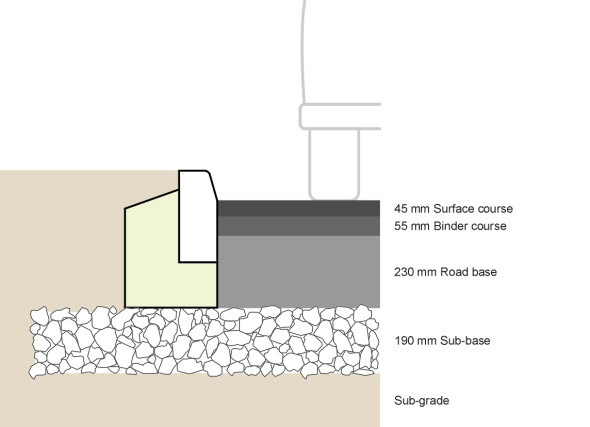
The total thickness of material depends on the level of traffic. For a moderately busy trunk road, including the sub-base, it might be of the order of 500 mm, with layers as shown in table 2 (see also figure 8). These layers are not meant to work independently and they don’t slide over one another when deformed under a wheel load: rather, they act together as a structural unit. The gain can be appreciated by means of a simple analogy. Imagine a pack of printer paper. If the sheets can slide freely over one another you can bend the pack quite easily, but if you glue them together you create a rigid block like a wooden breadboard for example. In the case of a flexible pavement, the bonding is carried out with a ‘tack coat’ or bond coat of bitumen that is often mixed with polymer additives.
| Surface course | 45 mm | Hot rolled asphalt |
| Binder course | 55 mm | High Density Macadam |
| Base | 230 mm | High Density Macadam |
| Sub-base | 190 mm | Local aggregates, unbound or open-texture macadam |
| Total | 520 mm |
Hence a multi-layered pavement is structurally complex owing the interactions between the various layers, and the stresses at any given depth cannot accurately be predicted from the Boussinesq formula. In any case, not all the important stresses – the ones likely to damage or destroy the pavement fabric – are compressive. It is widely assumed that there are two critical stresses, the first being tensile. It occurs at the bottom of the upper bound layers, and it can produce ‘alligator cracks’ at the surface when the pavement approaches the end of its design life. The second is the vertical compressive stress at the bottom of the underlying unbound layers, which results in rutting and cracking of the whole pavement [11]. These stresses are shown diagrammatically in figure 9.
Figure 9
We say ‘assumed’ because for some years now, our interpretation of the failure mechanism - and indeed the structural behaviour of the pavement in general - has been in some doubt. Notwithstanding the development of more complex theoretical models, the evolution of asphalt pavement construction has been governed as much by trial-and-error as anything else, and successful implementation of any particular scheme still relies a great deal on experience together with attention to the quality of materials and the conditions under which they are laid (for example, the weather). According to some, black top is a black art.
Rigid pavements
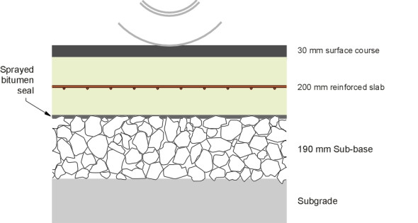
Paradoxically, a rigid pavement behaves more like a plastic ruler than a flexible pavement, albeit a very stiff one. A reinforced concrete slab, it bridges across soft patches and spreads the wheel loads over a relative wide area. While the slab forms the main structural component, it is usually overlaid with a thin asphalt surfacing, whose composition can be tailored to provide high skid resistance and low tyre noise, and can be renewed more readily than a concrete surface. The whole is placed on a cement-bound aggregate base.
Given that they are so robust, it comes as a surprise to learn that all concrete roads crack. They crack not because they are weak, but because concrete shrinks when it dries out after first being laid. It also expands and contracts with changes in temperature, and when the temperature falls, the contraction is resisted by friction with the material underneath. This puts the slab into enormous tension, which explains why the concrete is usually reinforced with a mesh of steel bars, whose role is not to strengthen the slab against wheel loads but to control the cracking (figure 10). At one time, it was common practice to insert construction joints at regular intervals to allow the contraction to take place: the concrete could then be laid as a series of separate slabs like tiles on a bathroom floor. But the joints in early concrete roads turned out to be vulnerable because compared with the centre of a slab, the edges have much less resistance to deflection under a wheel load. Consequently, as a lorry passes from one slab to the next, the edge of the first slab will be pushed downwards relative to the edge of the second slab. Repeated movements of this kind will weaken the joint sealing material. If water gets into the joint, matters quickly deteriorate, because each deflection pumps out some of the water under pressure, taking soil particles with it and enlarging the cavity underneath. To prevent this, steel dowel bars must be inserted between neighbouring slabs in order to provide continuity as wheel loads pass from one to the other, while still allowing for contraction. They function in much the same way as the fishplates that were once used to connect neighbouring lengths of rail on railway lines, that is to say, not very well.
Figure 10
Railway practice has moved on, and so has highway construction. Nowadays, the road base can be laid as a continuous slab, and the shrinkage managed in a different way. In a continuously reinforced concrete pavement, the cracks are accepted as inevitable, but the system is designed to ensure that they occur at frequent, regular intervals, partly by virtue of the reinforcement itself, and partly by moulding grooves in the slab at intervals of a few metres, or cutting them with a diamond saw a few hours after the concrete is poured. The cracks that subsequently form don’t affect the strength of the slab because they are only about 0.2 mm wide, and there is sufficient contact between neighbouring sections so that they interlock like stone setts or block paving. And once overlaid with asphalt surfacing, the slab as a whole is waterproof.
A similar technique is also used in ‘flexible composite’ pavements, which are essentially bitumen pavements with the base replaced by a cement-bound mix. Because it is a spongy concrete, the base is liable to contract and form lateral cracks at 10 – 30 m intervals, which will eventually show up at the road surface (a phenomenon known as reflective cracking). The solution is deliberately to induce cracks in the base at more frequent intervals. It seems that concrete pavements are among the very few artefacts that last longer if they are broken before being used.
How a pavement deteriorates
The surface of a road is continually under attack, not just from the impact of wheel loads but also from corrosion associated with noxious chemicals deposited by passing traffic. It is also affected by the ultra-violet radiation in sunlight, extremes of temperature, and immersion in water. All shorten its life.
Rutting and cracking
The main challenge is the cumulative impact of wheel loads, which can damage the structure of a pavement in either of two distinct ways: by forming ruts, or by inducing cracks. Ruts occur primarily because the underlying soil gives way, although squeezing of the pavement structure itself can contribute (compared with macadams, asphalts are more prone to deformation of this kind). The ruts occur mostly in the paths followed by the wheels of heavy lorries, so on a typical UK motorway, where a heavy lorry spends on average about three-quarters of its journey travelling in the inside lane, the damage is not spread evenly across the full width of the carriageway.
Tests on German highways have shown that rut depth in a flexible pavement is proportional to the square root of the number of load passes \(n\):
(5)
\[\begin{equation} \text{Rut depth} \quad = \quad a \; + \; b \sqrt n \end{equation}\]where \(a\) and \(b\) are constants. As with all forms of damage, the contribution to rut depth from a single axle increases sharply as the axle load increases; for example going from 10 tonnes to 11.5 tonnes magnifies the impact by about 50% [21].
The cracking process, on the other hand, develops in a different way. Crack growth occurs in materials of all kinds: glass, ceramics and metals for example. In many cases it limits the strength of a material that in theory should be able to carry a much heavier load, and if only for this reason has been the subject of scientific study for many years. Put simply, stress inside a material can be pictured as a fluid. A little bit like a river, or more accurately an electric current, it flows from the point of application of a load to the place where the load is finally relieved – typically the foundations of a building where it passes into the soil beneath. It cannot ‘travel’ through a crack or a cavity inside a material, so it deflects around it, and in the same way that a stream of liquid accelerates when it passes around an obstruction, the value of the stress increases because it is constrained to pass through a reduced cross-section of material. Consequently, near the tip of each crack, the stress is higher than it would normally be were the material intact. The highly-stressed region tends to crack in turn, so that in effect, once a crack or defect is present, it will tend to propagate like the roots of a tree. Tearing the material apart requires energy, and the energy comes not from a single load application but a series of repeated loading and unloading cycles. In a bitumen road layer, once it has begun, the cracking process grows exponentially thus [2]:
(6)
\[\begin{equation} \text{Crack length per unit area} \quad = \quad Ce^{n} \end{equation}\]So the pavement doesn’t give way suddenly like the cracking of a china plate. It behaves more like a ductile metal after reaching its yield point. If a paperclip is bent and unbent repeatedly, microscopically small cracks extend with every stress cycle so that the material weakens progressively until it breaks. Likewise, successive pounding by lorry wheels weakens a flexible pavement by creating fatigue cracks. For many years, the cracks were thought to start at the bottom of the bound layers where the tensile stresses are highest, extending exponentially with the cumulative number \(n\) of wheel impacts until they became visible at the surface. This is now in doubt.
The fourth power law
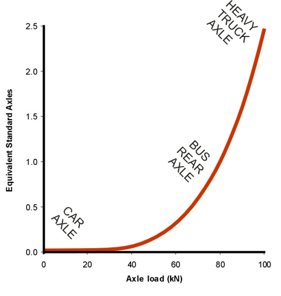
Experience with bitumen roads before 1939 revealed that the rate of wear is extremely sensitive to the weight of vehicles using them. The effect was first quantified during experiments carried out by American Association of State Highway Officials (AASHO) between 1958 and 1961 during which heavy trucks were run continuously over a series of six test tracks to achieve a specified degree of deterioration [1]. The results led to an empirical relationship between axle load \(W\) and the number of passes \(N\) of that axle load required to achieve the same damaging effect as one ‘standard axle’ \(W_{0}\) of 18,000 pounds – around 80 kN. The fitted curve took the form
(7)
\[\begin{equation} N \quad = \quad \left( \frac{W}{W_0} \right)^4 \end{equation}\]The exponent ‘4’ on the right hand side is an approximate figure. It varies appreciably according to the type of road and makes no distinction between different types of damage, namely rutting and cracking [9]. Nevertheless, the relationship points to sharp differences in the effects of different kinds of vehicle. For a heavy truck, one axle will do more damage than over 10,000 cars, and the damage is increased by a factor of two if the load increases by a relatively small margin - 20% - above the standard figure. In this sense, the construction and maintenance of a national highway network must be tailored to the needs of heavy lorries. For practical purposes, family cars and other light vehicles can be ignored (figure 11).
Figure 11
Water and frost
Under the action of repeated wheel loads, all pavements will form minute cracks at the surface, which let in small amounts of water. The cracks slowly enlarge, wedged open by particles of detritus. Water that penetrates the carriageway surface has a marked effect on the lifetime of the pavement: it strips bitumen from the aggregate, erodes the bonds between layers, and reduces the bearing capacity of the subgrade [18]. The stripping occurs when water fills the voids and the pressure pulsates under every passing wheel load, so that the damage in wet weather is many times that in the dry.
Figure 12
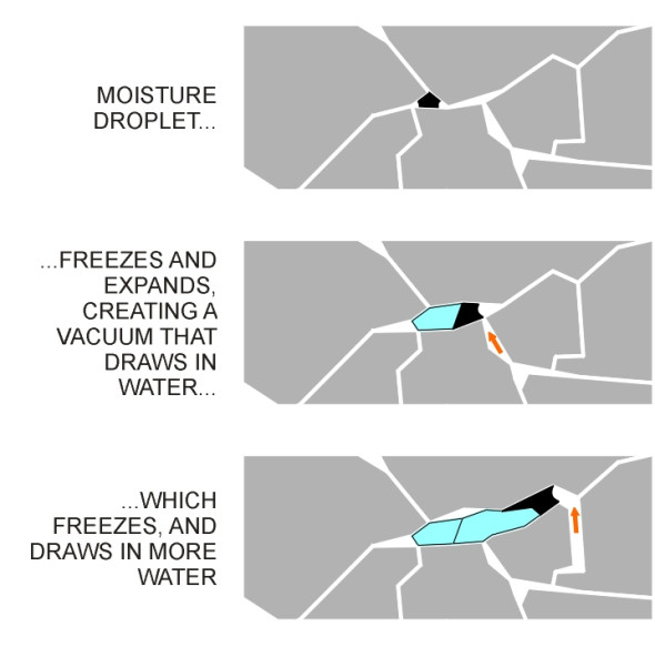
In northern countries, water poses an additional hazard in winter because it freezes, and when water freezes it expands by about 9%. The force that this generates can shatter porous stones, releasing loose particles that scour the road surface and widen any cracks [16]. These expansive forces can damage the road in another way, by lifting the surface layers bodily upwards and creating voids that draw up more water from below. At only one degree Celsius below freezing, the suction pressure is around 10 atmospheres [16]. The newly-attracted water freezes in turn, creating more suction which draws in more water. Once begun, the process can form ‘lenses’ of considerable size (figure 12), a phenomenon known as frost heave. Frost heave is one of the reasons why engineers try to ensure that the water table is at least a metre below formation level when building a new road.
How long will it last?
If carefully built, a bitumen-based flexible pavement can last 40 years, although to remain serviceable, the surface will need to be renewed every ten years or so. A concrete pavement can last almost indefinitely but it, too, will need resurfacing at regular intervals. So any statement about the lifetime of a pavement must take into account two considerations: (a) which part of the structure are we talking about, and (b) what do we mean by ‘unserviceable’?
Failure criteria
Pavement deterioration usually manifests itself in one of three ways: (a) the surface becomes polished and slippery, (b) the surface deforms, or (c) it disintegrates. We looked at skid resistance in Section C1603, and here we’ll concentrate on deformation and wear. Surface deformation becomes critical when it affects the safe movement of vehicles. In a sense, the surface is distorted from the moment when the carriageway is built, because while roads are constructed more accurately than used to be the case, there may be errors in the vertical alignment up to several millimetres from the values specified in the design. Furthermore, deformation routinely occurs under the tyres of heavy vehicles from the day when the carriageway is first opened. Under a fully laden lorry, a well-constructed flexible pavement will deflect a maximum of 0.2 mm, although some minor roads might deflect up to 1 mm [10]. However, deflections of this order are ‘elastic’ like the deflections of a steel spring: when the load is removed the surface springs back to its original shape. For a major road, only when deflections exceed 0.5 mm are they considered symptomatic of a weakened pavement in need of attention [19]. Ruts are different because they indicate permanent deformation of the underlying layers. In practice, a highway authority may consider failure to have occurred when the rut depth reaches 20 mm, and in many countries a depth of 10 mm will trigger investigation.
As we have already seen, cracking can quickly lead to complications. In some European countries, a crack length of 60 – 100m per 100 linear metres of road is considered as symptomatic of failure, and therefore requires action [3]. In other countries, the threshold is taken to be cracking that affects more than 50% of the wheel path. However, much depends on the width of the cracks. Anything less than 2 mm in width in an asphalt material is considered ‘minor’, and greater than 2 mm, ‘major’.
To summarise, during the wearing process both rutting and cracking occur in parallel but at different rates. The visible signs of rutting usually appear first, but once cracks appear, they accelerate more quickly. Consequently, there is no cut-and-dried threshold marking the point at which the pavement ‘fails’, and indeed, a cracked or rutted pavement may continue to give useful service for some years provided it is suitably treated with, for example, an overlay.
Pavement life
In many countries, road traffic growth has outstripped predictions. Not only are drivers having to queue in traffic jams, but roads that were designed to last for twenty years or more have worn out within a few years of opening. Unfortunately as motorists we don’t take into account the cumulative nature of the ageing process. It is quite different from the ageing process of other structures such as bridges, where the effects of weather and corrosion often dominate: given suitable treatment, a bridge might reasonably be expected to last for 150 years. But the life of a road shortens with every passing vehicle, so that in periods of steady economic growth, motorists are presented with a network that seems constantly under repair.
The life cycle of a road is in any case hard to pin down because different parts are replaced at different intervals. Stages in the life cycle of a pavement might be summarised as shown in Table 3, which is based on material originally published by Derek Pearson [14]. It now appears that heavily trafficked flexible pavements can last much longer than they used to without having to increase the construction depth by identifying ‘failure’ much earlier in the lifecycle and applying remedial treatment before surface cracking begins to affect the structure as a whole. The design life of pavements in the UK is progressively being set at 40 years.
| Operation | Time interval |
| Preventative maintenance of surface | 10 years |
| Rehabilitation (replacement of surface and binder courses) | 15 – 20 years |
| Strengthening with overlay | 20 years |
| Reconstruction | 40 years |
Maintenance
Since a large part of the national roads budget is devoted to maintenance, it is vital to monitor road surfaces for deterioration, and as far as possible, for engineers to use consistent and verifiable criteria for assessing whether, and when, treatment is needed. Skid resistance testing is carried out using specially adapted vehicles. The stiffness of the road structure as a whole can be assessed by measuring surface deflection under an instrumented wheel load, with a device known as a deflectograph. But checking for other types of structural defects is harder. Highway engineers inspect cracks and rutting visually, and take specimen cores drilled out from the body of the pavement. The process is labour-intensive and assessment of the results relies a good deal on judgement. Automated monitoring can take over some of burden and improve the decision-making process. Many governments have now established automated monitoring systems for trunk roads that produce results quickly and cheaply, using surface measurements collected from moving vehicles fitted with laser sensors and video cameras. However, it is not easy to apply the process in towns and cities, where many people park in the carriageway outside their homes.
Conclusion
Road construction is among the most specialised branches of civil engineering, with its own vocabulary and design rules. In spite of the engineer’s best efforts, the results don’t always turn out how one might wish. There are four main reasons for this. First, traffic growth is unpredictable. Second, the lifetime of the pavement materials depends to some extent on the conditions under which they are laid; for example, cold wet weather during the construction period can drastically shorten the life of a road because it stiffens the bitumen and prevents it from compacting properly. Third, the strength of a road depends on the strength of the ground underneath, and the ground varies from one stretch of road to the next, sometimes turning from solid rock to quagmire in just a few metres.
Finally, the behaviour of a pavement under traffic loads is not entirely understood. Until recently, engineers believed that in structural terms, roads fail from the bottom up. Cracks on the surface arise from of cracks lower down, which in turn are caused by tensile strain at the bottom of the bound layers. The logic behind this assumption is straightforward. The largest tensile stresses in a loaded beam of the kind that holds up your bedroom floor always occur along the lower face, which is pulled apart as the beam sags in the middle. Cracks are usually associated with tensile forces, and if you think of the bound layers of the pavement as a beam laid on a spongy surface, it seems obvious that the largest tensile forces will occur at the bottom. Hence the cracks must start well below the surface and work upwards. However, this is now in dispute because the evidence suggests otherwise; over the last twenty years, many roads have cracked at the surface without any sign of failure below. It seems that our understanding of the process is due for an overhaul, and eventually this will be reflected in the way that pavements are designed and the way they perform.