© Joanna Walpole
C.0505
Steering
When a new car first appears on the market, publicity photos will show it with the front wheels swivelled dramatically at full lock. But this is not a typical position. Most of the time, the front wheels of your family saloon point within a degree or two on either side of the straight ahead position. The angle of a wheel at any given moment is known as the steering angle. At high speeds, the steering angle is barely noticeable, because quite a small change can fling the car sharply to one side. It follows that precise engineering of the steering and suspension is needed to ensure that the driver’s hand movements are communicated faithfully to the front wheels. And if for some reason the driver lets go of the handwheel, it is vital that the steering centres itself automatically so that the vehicle continues in a straight line as opposed to veering off the road. Precision is also important for reducing tyre wear. If the angles taken up by the two front wheels are not compatible, they will ‘scrub’ the road surface and slow the vehicle down. The effect can be noticeable even at low speeds in parking manoeuvres. If you have ever built a model car with front wheels that swivel exactly in parallel, you’ll have noticed how they grind across the table top during sharp turns. It was this problem that led the designers of early automobiles to develop the ‘Ackermann’ steering layout, which has survived on motor vehicles in modified form until the present day.
Ackermann steering
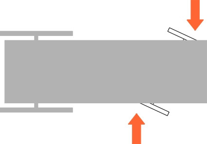
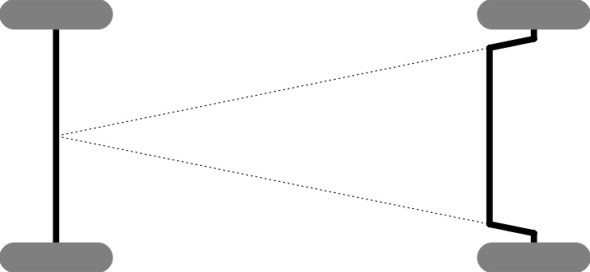
Early carriages were designed with the front axle mounted on a single pivot on the vehicle centreline (figure 1). Anything more complicated would have been difficult to make, but the single pivot wasn’t ideal. On a sharp curve, the lateral distance between the front wheels was effectively reduced, which made the carriage more likely to overturn. Also the wheels tended to foul the undercarriage (figure 2), and a jarring bump in the road would knock the steering out of line.
Figure 1
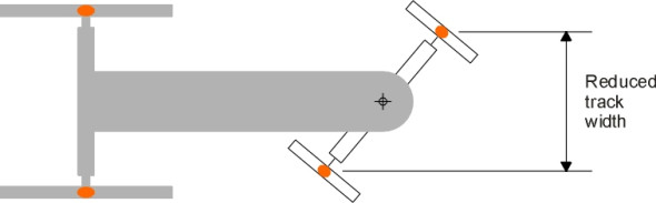
Figure 2
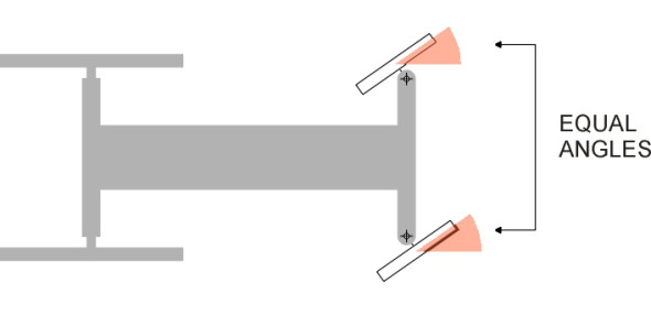
A much better option was to make the front wheels swivel independently, and there is still disagreement about who managed it first. One thing is certain, that it was not Mr Ackermann. German coachbuilder Georg Lenkensperger built a prototype in 1816 in which the wheels swivelled independently but remained parallel (figure 3). The UK patent was held by his friend, Rudolf Ackermann, a renowned book dealer. Lenkensperger’s idea did not catch on in the UK, owing largely to conservative attitudes in the coachbuilding industry [1]. Only much later in 1878 did Charles Jeantaud succeed with an improved layout in which the wheels turned through different angles [2] [14].
Figure 3
Ackermann geometry
At this point we pause for a moment, and imagine the car as having only a single wheel at the front and a single wheel at the rear. We shall refer to this imaginary configuration as the ‘thin car model’. When it goes round a curve, the front and rear wheels follow paths of different radius, so we must choose one of them to represent the motion of the pair. The equations are simpler if we choose the rear wheel. Then as shown in figure 4, in order for the rear wheel to follow a curve radius of \(R\), the front wheel needs to swivel through a steering angle \(\delta\) given by
(1)
\[\begin{equation} \delta \quad = \quad \arctan \left( \frac{L}{R} \right ) \end{equation}\]This angle is known as the Ackermann angle.
The real vehicle can be pictured as two thin car models side by side spaced a distance \(w\) apart as shown in figure 5. We now have four wheels all travelling along curves of differing radii, so we need to choose a reference point on the car that will represent the path of the vehicle as a whole. The point we choose is the centre C of the rear axle. On a circular track, if C moves along a curve of fixed radius \(R\), then as shown in figure 5 the inner pair of wheels follow a curve of radius \(R - (w/2)\) and the outer pair a curve of radius \(R + (w/2)\).
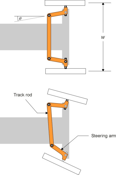
You can see from the diagram that the steering angle of the outside front wheel must be smaller than \(\delta\) because its path intersects the vehicle chassis at a shallower angle. Similarly, the steering angle of the inner wheel must be larger. Throughout the twentieth century, most land vehicles used the same trick to achieve this, and many still do. Each wheel is mounted on a short stub axle that is pivoted at a kingpin. The kingpin is arranged as close as possible to the central plane of the wheel. Attached to each kingpin is a steering arm, and the two steering arms are connected by a track rod running across the width of the front suspension. Moving the track rod from side to side makes the front wheels swivel simultaneously (figure 6). On passenger cars today, the track rod has been superseded by a ‘rack-and-pinion’ system, but we’ll ignore this for the time being because it doesn’t greatly affect the geometry. What matters most is the angle of the steering arms, which are not parallel: each steering arm is inclined at an angle \(\theta\) to the plane of the wheel to which it is attached.
Figure 4
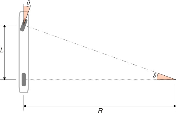
Figure 5
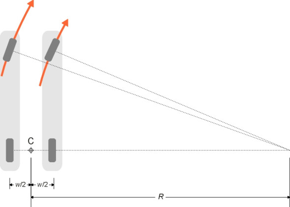
Figure 6
Compensation
Ideally, one would choose the angle \(\theta\) of the steering arms to guarantee ‘pure’ rolling with no tyre scrub. From equation 1, we see that the steering angles of the inner and outer wheels must be respectively
(2)
\[\begin{equation} \delta_{i, \, ideal} \quad = \quad \arctan \left( \frac{L}{R - \frac{1}{2}w } \right) \end{equation}\](3)
\[\begin{equation} \delta_{o, \, ideal} \quad = \quad \arctan \left( \frac{L} {R + \frac{1}{2}w} \right) \end{equation}\]Values of these two angles are plotted against the Ackermann angle \(\delta\) in figure 7 for a car with wheelbase 5 m and track 2.5 m. As one might expect, the steering angle for the inner wheel is always larger than that for the outer wheel, but the difference diminishes as the Ackermann angle is reduced to zero so that when the car is moving in a straight line, the wheels are parallel. In theory, a steering linkage that matched these curves exactly would eliminate tyre scrub, and the front wheels would have perfect Ackermann compensation.
Figure 7
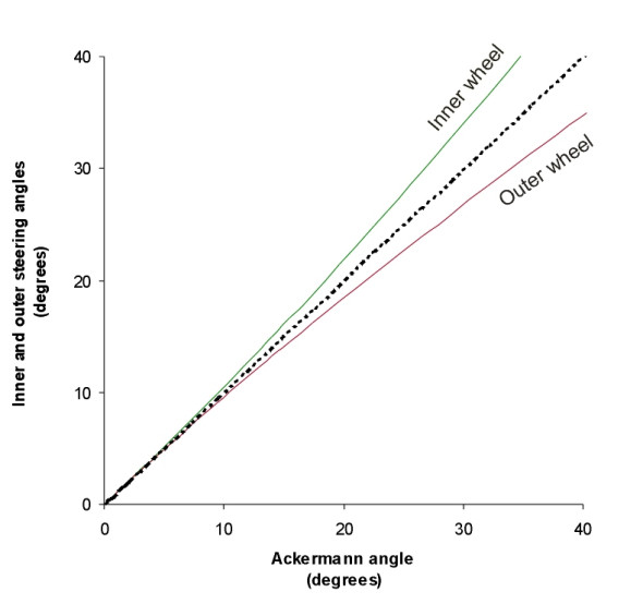
Figure 8
But in reality there is no value of \(\theta\) for which the linkage shown in figure 6 reproduces these steering angles exactly over the whole range of handwheel movement from left lock to right lock. For early cars, it was traditional to arrange the geometry so that the projections of the steering arms intersected at the rear axle (figure 8), which was thought to be a reasonable compromise [7]. Nowadays, most cars retain a smaller degree of Ackermann compensation, with the point of intersection of the steering arms aft of the rear axle [14]. The degree of compensation can be gauged by measuring the actual steering angle \(\delta_{o, actual}\) given to the outside front wheel and comparing it with the ideal value \(\delta_{o,ideal}\) using the following formula (this is a simplified version of the one that appears in [2]):
(4)
\[\begin{equation} \text{Ackermann fraction} \quad = \quad \frac{\delta_{o, \, actual} \; - \; \delta}{\delta_{o, \, ideal }\; - \; \delta } \times 100\% \end{equation}\]Typically, road cars have approximately 40% compensation at steering centre, possibly rising to 60% at full lock [3]. We’ll return to this matter later in section C0504.
In practice, the engineering of a steering system is more difficult than pictured here. During any journey, the car will roll a little from side to side on curves, which causes the wheels to move up and down relative to the chassis. They will also deflect over bumps in the road surface. Deflections of either kind will distort the steering linkage and affect the relationship between steering input and output. Careful design is needed to overcome these effects. And since the engine compartment is usually overcrowded, for front-wheel drive cars there may not be room for the track rod immediately behind the kingpins [8], and the tracking assembly is sometimes mounted ahead of the axle. There is another possibility for cars with a Macpherson strut suspension: the casing for the rack and pinion can be bolted to the bulkhead at the rear of the engine compartment, and connected to lever arms that are welded to the top of each strut, so that the whole lies above and behind the engine. A good picture of this arrangement is shown in [15].
The handwheel
Nowadays we expect the front wheels of a car to swivel easily from lock to lock so we don’t have to wrestle with the handwheel while manoeuvring into a cramped parking space. But if anything, the physical effort needed to steer at low speeds has increased with the trend towards heavier cars together with front-wheel drive and wide tyres. Each front-wheel may be carrying a load approaching half a tonne.
Reduction ratio
The effort can be reduced by increasing the gearing ratio built into the steering system. Typically, the front wheels must be capable of turning through an angle of \(\pm 40^{\circ}\) from left lock to right lock [11], while the handwheel is turned through several complete revolutions. The gearing ratio is commonly expressed as the number of degrees of handwheel rotation needed to produce one degree of steer angle.
The most suitable value for the reduction ratio depends on how you intend to use your car. Racing drivers prefer a smaller value so they can carry out spectacular manoeuvres with relatively small hand movements. But for ordinary cars, a high value lightens the steering task especially when parking, and a common figure is 16:1, although different specialists quote different ranges (see for example [4], [9] and [11]: also, cars with power-assisted steering manage with less). A high ratio has another advantage: at high speeds on public roads, a small input, say, a steering angle of \(0.5^{\circ}\), can generate lateral forces that use up all the friction available in the tyres, in other words, the car skids. So a large reduction ratio reduces any risk arising from an unintended movement of the handwheel. With a reduction ratio of 16:1 to 18:1, the driver can turn the handwheel through 10-20\(^{\circ}\) without necessarily losing control [4]. Another way to reduce the risk is to make the handwheel resist motion when travelling at speed, and various manufacturers have experimented with hydraulic systems that stiffen the response accordingly. For example, Citroen gave its 1970 Citroen SM its power steering with artificial ‘feel’, in which the steering grew heavier at speed [18].
Finally, a large steering ratio reduces the likelihood of the handwheel being wrenched out of the driver’s hands when one of the wheels hits a pothole. Another way to achieve this is to make the system ‘irreversible’. Except for heavy vehicles, irreversible systems are today less common than they used to be, but at one time, they included the screw-and-nut device, and later, the worm-and-gear. With either system, the act of turning the handwheel (input) delivers torque to a drop arm connected to the track rod (output) but not the other way around.
Feedback
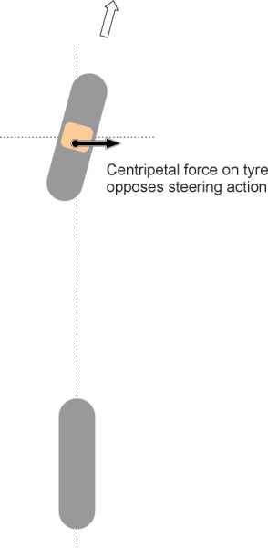
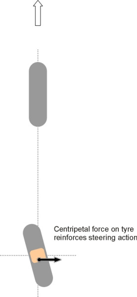
An irreversible mechanism ensures that when a front wheel bashes into a pothole, the driver doesn’t receive a kick from the handwheel. And yet, if we encounter an icy patch on a bend, we expect feedback – we want the handwheel to provide ‘feel’ of the road surface conditions at all times. At first sight these requirements seem contradictory, but in fact they refer to two different things. Bumps that ‘kick’ the steering are generally undesirable, not least because any such reaction knocks the wheel off line and changes the direction of the vehicle. That is why the kingpin of a car suspension is angled inboard at the top: the axis around which the wheel swivels then passes close to the centre of the contact patch, which minimises the torque impulse from any sudden impact (see Section C1405). By contrast, the steady tug on the steering wheel that occurs on a bend arises from a different source: the centripetal force applied through the contact patch, which tends to swivel the wheel back towards the straight-ahead position (figure 9). The more extreme the manoeuvre, the greater the reaction. Here, the feedback provided by the handwheel tells the driver something useful, and in the event that too much is demanded of the tyres and they start to lose grip, the steering will ‘loosen up’ and perhaps give some warning of what is about to happen.
Figure 9
Steering systems
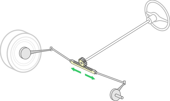
The most widely used steering system today is rack-and-pinion steering, which was pioneered by BMW in the 1930’s [17]. The track rod is split into three sections. The central ‘rack’ has raised teeth, and it is enclosed in a steel tube. A pinion (gear wheel) on the end of the steering column engages with the rack so that any movement of the handwheel causes the track rod to move from side to side, providing accurate and reliable control (figure 10). Details of other steering mechanisms can be found in, for example, [6], [10] and [16]. A useful overview of lorry steering can be found in [13]. We shall not go into detail here, but there are two points worth mentioning.
Figure 10
Power steering
Many drivers need some form of power to help them turn the handwheel on tight curves. The main options are (a) power steering and (b) power assistance. The names are not very informative but there is an important difference between the two systems. A power steering system senses what the driver wants and replaces the driver’s input with a more powerful signal. Should the external power fail, steering is lost and the driver has no control. By contrast, a power-assisted system works in parallel with the mechanical system so that the mechanical link is not broken. It senses the driver input and augments it via a ram that engages with the drop arm or track rod. It is controlled by a sensitive transducer inserted at some point within system to gauge the pressure exerted by the driver on the handwheel. This is the approach followed in almost all systems in use today. For example, in one particular system the upper steering column is joined to the lower via a spring that compresses when the handwheel is turned. The spring controls a valve that in turn determines the degree of assistance. But the two halves of the steering column are also connected by a mechanical ‘dog’ that provides fail-safe reversion.
Until recently, most power-assisted systems were hydraulic, with the extra steering torque provided via a hydraulic pump driven by the engine. Hydraulic servo assistance provides 80 - 85% of the power needed for heavy vehicle steering, and 70 - 75% of the power needed for saloon cars [12]. The reduction ratio can be lowered at the same time, giving a more responsive steering feel. However, electrically powered systems are now preferred to hydraulic ones, because they can be managed with digital control routines that simultaneously perform other functions such as traction control. Sooner or later, manufacturers will introduce ‘drive-by-wire’ in which there is no mechanical linkage between handwheel and steering arms at all. Not only will it be lighter, it will fit more easily into a cramped engine compartment, and allow the designer to program any chosen regime of steering characteristics into the system that might be thought desirable. The only question will be, what happens when the power fails?
Rear wheel steering
Everything we have said so far assumes that the steering action takes place at the front wheels. This has not always been so: some early cars were fitted with rear wheel steering with the front wheels permanently fixed in the ahead position. But they were unstable because it was necessary for each rear wheel to trail slightly behind its kingpin axis like the castor on a supermarket trolley. Otherwise any small deviation from the straight ahead position would cause the wheel to flip round 180 degrees (figure 11). Castor trail works fine on the front wheels of a vehicle because it is self-centring, a point that we have covered elsewhere (Section C1405). But on the rear wheels it does exactly the opposite. When the car travels round a curve, the centripetal force tends to swivel the wheel further and increase the steering angle. An increase in the steering angle in turn causes the vehicle to corner more sharply, which leads to a greater centripetal force, and so on (figure 12). With a conventional steering system on the rear axle, a vehicle that entered a corner too fast would quite likely spin round in a circle before the driver knew what was happening.
Figure 11
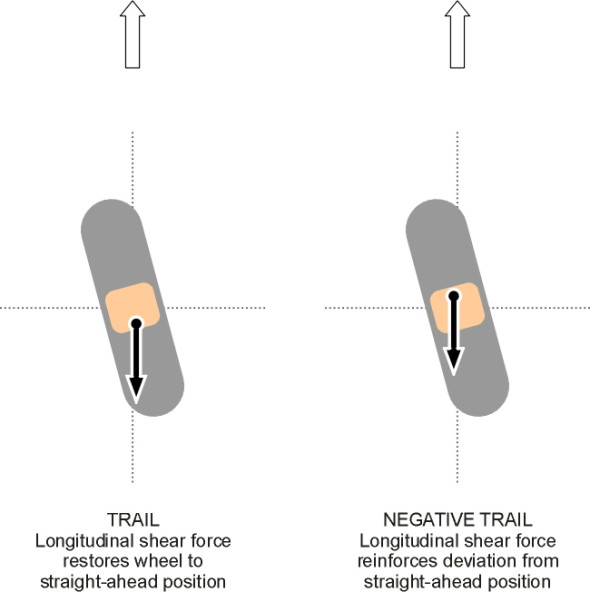
Figure 12
Loose ends
Rear-steering vehicles are fundamentally unstable. Yet Buckminster Fuller’s famous Dymaxion of 1933 seemed to run quite well [5]. Furthermore, during the 1990s several luxury car models were produced in which a degree of rear-wheel steering was introduced to improve handling. How did the designers avoid instability?
Acknowledgement
Photo on opening page of Mini cornering at Goodwood by Joanna Walpole.
Revised 19 February 2015