R.1605
The steel rail
Let us step back in time before railways were invented and imagine what it was like trying to improve the transport system at the beginning of the nineteenth century. There were horse-drawn carriages, but not many places where they could be driven at speed because the roads were bumpy and liable to subside. The problem was how to support the weight of a rolling vehicle. With a static object it’s easy. A house can be built with foundations that spread the load, and if the ground is soft we can make the plan area as large as we want so the building doesn’t sink. But a wheel does the opposite: it concentrates the load, and if we want it to roll freely, other things being equal we must make the contact area as small as we can. So there are two conflicting requirements: (a) to spread the load to protect the ground, and (b) to concentrate the load to make the wheel efficient. An obvious solution is to lay a hard material along each wheel track: for example, wooden planks will both spread the load and provide a hard surface that will reduce the contact area and hence the rolling resistance. A steel beam would be better still. It has a hard surface that offers little resistance to a rolling wheel, and it can distribute the load over a large area by bridging across local unevenness in the ground surface. The concept of two steel rails at constant spacing emerged during the nineteenth century as the basis for the railways that we have inherited today. They represent a large investment, locked into the national infrastructure so the configuration is unlikely to change during the next few years at least. In this Section we shall try to explain why the rail taken on its present shape, and what developments might be in store.
Form and substance
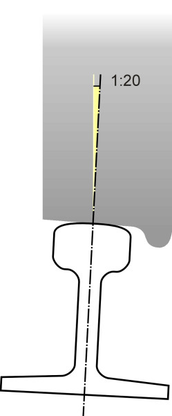
If you’re a rail commuter you’ve probably spent many hours looking at railway track. And you will have noticed that the cross-section of the rail is not rectangular like a timber joist, but rather it is built up from different elements: a flat bottom, a thin upright web, and a bulbous head that provides the running surface (figure 1). Less obvious is the fact that the rail doesn’t stand quite upright. For reasons explained in Section R1610, the wheels of a conventional railway vehicle are machined to a conical profile. You can picture the tread as a slice taken out of a long, narrow cone whose surface slopes at a small angle so it doesn’t sit horizontally on the top of the rail. The rail is therefore tilted at the same angle so that the plane of contact is at right-angles to the web and the centre of the contact patch lies in the middle of the railhead (figure 2). At one time 1:20, the angle is now fixed at 1:40 in Japan and across much of Europe [4] [30]. There are exceptions: tram track has a vertical rail, as do the short sections that make up the turnouts and crossings on a conventional railway track.
Figure 1
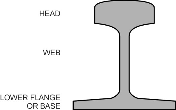
Figure 2
The rail cross-section
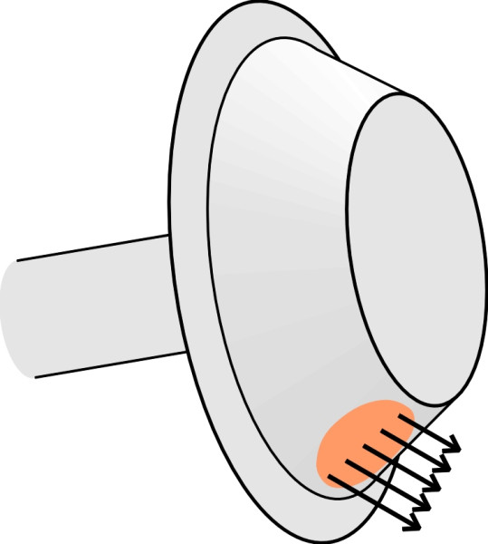
In cross-section, the top of the rail is not flat but curved. Traditionally, the curve is made up of circular segments each of different radius. One example is the US standard 115RE light rail, whose approximate dimensions are shown in figure 3 (details of the profile can be found in [29]). To understand why it is curved rather than flat we need to look at the wheel profile. Let’s mentally divide the tread surface into rings whose diameter increases gradually from the outer part of the tread to the inner part next to the flange. If you think of the train as stationary with the track flowing past underneath, you can see that each point on the innermost ring covers more distance in one revolution than its counterpart on the outer ring as shown in exaggerated fashion in figure 4, where the wheel is pictured from below with the contact patch coloured in orange. It follows that the inner ring is moving slightly faster than the rail and the outer more slowly, and both slipping along the rail surface but in opposite directions. Only in the centre of the contact patch is the speed of the tread exactly matched to the speed of the rail. The result is a small but significant degree of grinding. Its effects can be minimised by making the contact patch exceedingly small, and the best way to do this is to use hard materials and to curve the top of the rail. However, once the wheelset enters service, the tread and the rail surface wear each other down and converge towards the same shape. Hence the rail head is made bulbous and heavy so it can accommodate a good deal of wear before the rail as a whole must be removed and replaced.
Figure 3
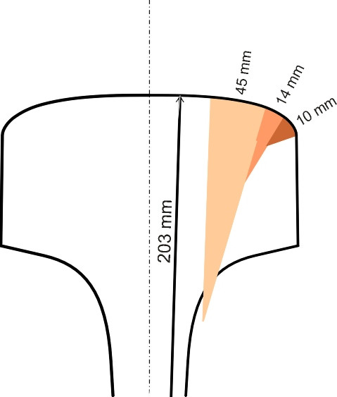
Figure 4
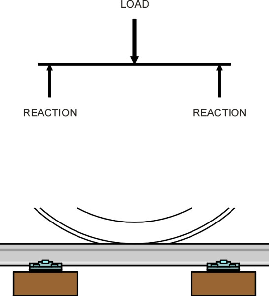
But why the narrow waist and the flange at the bottom? In some ways the profile resembles the ‘I’ section of a steel beam you would find in a multi-storey building. The I-beam has two flanges connected by a vertical plate known as the web. If you place a heavy weight on a beam between two supports, the load is carried along the beam and through the supports to the ground beneath. A load applied in this way does two things. First, it bends the beam, which the beam resists by developing a compressive stress near the upper surface together with a tensile stress towards the lower surface (figure 5). It makes sense, therefore, to shape the cross-section so that material is concentrated at the top and bottom where the tensile and compressive stresses are highest. Second, the load induces a shear stress (figure 6) that is carried mostly by the vertical web. The web also joins the upper and lower flanges so they work together as a unit. A steel rail follows the same logic because its main purpose is to act as a bridge that carries the wheel load to the nearest available supports, i.e., the sleepers immediately upstream and downstream (figure 7). The profile is usually attributed to Irish-born engineer Charles Vignoles, who worked in Britain during the 1830s [2] [31]. The Vignoles profile is similar to the I-beam except that the upper flange is thicker and narrower so as to provide a robust platform for the wheel loads together with a margin for surface wear.
Figure 5
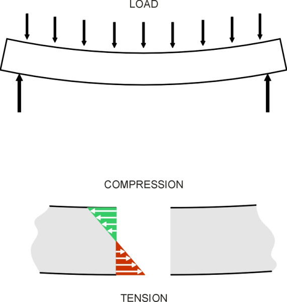
Figure 6
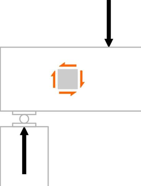
Figure 7
You can find examples of standard profiles for rails from different countries in [19]. Within the EU, they are now identified by their weight followed by the letter E then an index number, for example 50E1 refers to a rail weighing 50 kg per metre [31]. Common sense suggests that other things being equal, a heavy rail will be stronger than a lighter one, and indeed, rails of different weight are recommended by the UIC for different daily traffic loadings [31]. With a metre of rail weighing nearly as much as an adult human, it is clear that handling rails during maintenance is heavy work. Rails are made in standard lengths, and in the UK during the 1960’s when rails were still manually levered into place, a 60-foot length weighed one ton and took 20 men to lift. Nowadays the handling is carried out by machines.
The material
Modern rails are made from steel. The term ‘steel’ is really a collective name for a variety of alloys of iron and carbon often with other metals added. By varying the mix and treating the raw material in different ways one can tailor its properties for different uses. Railways, for example, use large quantities of steel to replace worn track, and the steel must be strong enough not to distort or buckle under load, tough (with high fatigue resistance so it doesn’t crack under repeated loads), and hard so it resists wear. And preferably cheap. Accordingly, rail steels are usually low-cost carbon alloys whose structure at the microscopic level is known as pearlite. The grains of pearlite are made from many layers: sheets of iron called ferrite separated by thin sheets of cementite (Fe3C) [14]. The mechanical properties of the steel are determined largely by the thickness and spacing of the cementite layers. In general, the higher the carbon content and the more closely-packed the cementite layers, the harder and stronger the metal, characteristics that tend to go together in carbon steels [11]. But a high carbon content tends to reduce fatigue resistance, and this is why railway engineers prefer instead to harden the upper running surface of the rail through heat treatment [8], which greatly increases the wear resistance and lifetime of the rail. Tables showing different grades of steel used in various countries together with their chemical compositions can be found in [15], and more information on rail steels generally in [9] and [31]. The steel most commonly used on European railways carries the designation R260. It has an ultimate tensile strength of 900 MPa [10]. Switches and crossings must resist high impacts, and the key components are generally made from manganese steels [16].
Rail technology
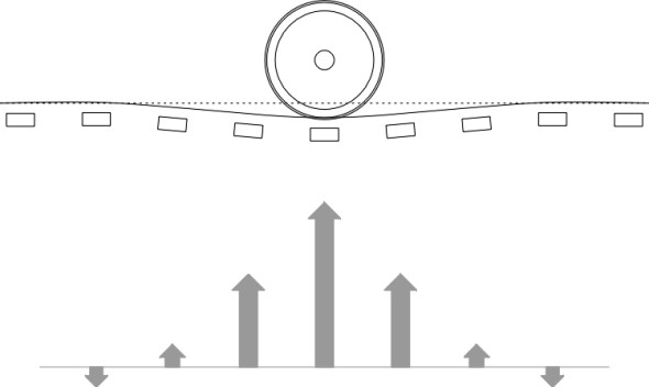
When we said earlier that the rail acts like a bridge between adjacent sleepers this was a simplification. In fact, the rail bends in such a way that the load is carried mainly by the nearest 3 or 4 sleepers, with possibly a small negative contribution from more distant ones, so the pattern of reactions acting on the rail appears roughly as shown in figure 8, and we’ll return to this aspect later in Section R1602. As well as vertical forces, there are also lateral forces that tend to tip rail over on its side. They arise on curves where the wheel flanges of a vehicle moving at speed press against the outer rail. On straight track the wheel flanges can bang against the rail if the vehicle starts to zig-zag from side-to-side. For all these reasons the rail must be securely fixed to the sleepers and the fixings must not work loose with repeated impacts.
Figure 8
Fixings
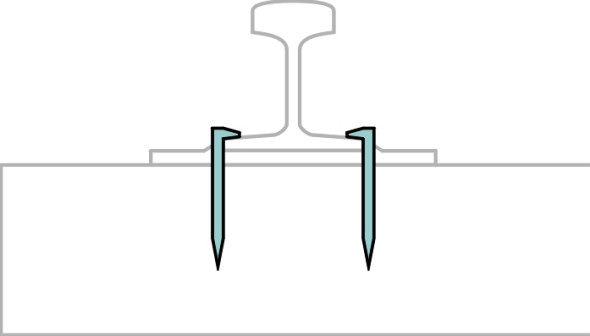
The transcontinental railroad that crosses the USA was originally built in the 19th century by two separate teams, one starting in the east and the other in the west. On 10 May 1869, the two halves were finally joined. The occasion took place near Promontory Point in the state of Utah, where the final spike was driven. In those days, spikes were used to fix the rails to the sleepers. Around six inches (150 mm) long with a chisel point (figure 9), they could be hammered quickly into place, this being the last operation in a sequence of operations that allowed the track to be laid as fast as the ground could be prepared ahead of the construction team. Simple and cheap, spikes are still used on some railroads in the United States today.
Figure 9
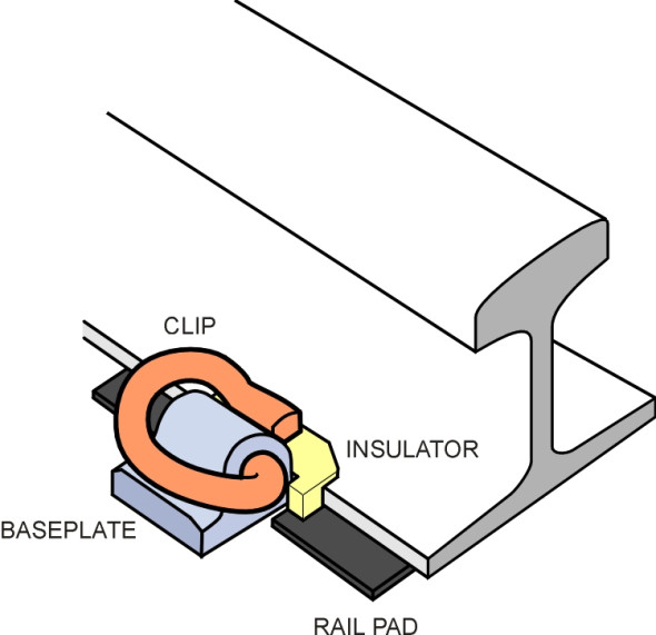
But mostly, timber sleepers are being replaced by concrete, which requires a different method of fixing. Mounted on each sleeper are two resilient pads up to 10 mm thick that soften the impact of heavy wheel loads moving at speed. They also insulate the rail electrically so it can form part of the circuit used to detect the presence of a vehicle in any given section of track, and also enable the rail to be used as a return for power current on electrified lines. Sitting on top of the pad is a base plate that is bolted to the sleeper. The bolts are located in steel sockets that are cast into the concrete. Finally, the rail is attached to the base plate by a patented clip that does not work loose, but can easily be removed to facilitate maintenance. There are several types, for example, the ‘e’-shaped Pandrol clip (figure 10) that was first used in the UK in 1959. There are many alternatives [33].
Figure 10
Continuously welded rail
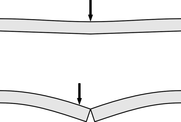
If an object is left outdoors, its temperature will vary over a wide range across the hours of the day, warming up in daylight and cooling down at night. Its mean temperature will also vary between summer and winter. Unfortunately, a metallic object like a steel rail will expand when heated and press with great force against anything that resists the expansion. Partly for this reason, during the first half of the twentieth century, rails were laid in short lengths and joined with slotted plates called ‘fishplates’ to allow for thermal movement. But the joints were a source of weakness and would deflect up and down over a much greater distance than the main body of the rail when a wheel passed over them [5], rather like the joints on early concrete motorways (figure 11). The impact made the ride noisy, wore the tip of each rail, and loosened the fishplate bolts so they had to be checked and tightened regularly.
Figure 11
Eventually, jointed track was superseded by continuous welded rail (CWR). In principle, a steel producer can supply rail in almost unlimited lengths because manufacture is nowadays a continuous process [6], with raw material fed in at one end and a continuous flow of rail emerging at the other. However, it can’t be transported in this form: it must be cut into shorter lengths, the standard length being 36 m throughout most of Europe. These standard lengths must then be joined together again on site to form rail that is continuous over many kilometres. There are three ways of doing this. The first method, electric flash butt welding, requires a heavy electrical current to be passed across the gap, which melts the ends of the rail and fuses them together. The second is a more conventional form of electric arc welding. The third is a proprietary chemical process known as Thermit welding. An early form of the process was first patented by Dr Hans Goldschmidt in Berlin in 1895. It relies on an exothermic chemical reaction: when ignited in a mould applied temporarily to the gap between two rails, aluminium powder reacts with iron oxide, capturing the oxygen and at the same time releasing a great deal of heat. The resulting molten fluid welds the two rails together. An animated cartoon showing how the process works can be found on the manufacturer’s web site listed at the end of this section.
Continuously welded rail has a major drawback: it expands and contracts with changes in temperature. Its coefficient of thermal expansion \(\alpha\)is about \(12 \times 10^{-6}\) per degree Celsius, so that if its temperature rises by \(1^\circ{}\), a rail will expand by \(12 \times 10^{-6} \times 100\% = 0.0012\%\), or about one part in a thousand. This may not seem much, but continuously welded rail is not actually free to expand, and if you firmly clamp a specimen at both ends, a \(1^\circ{}\)C temperature rise has the same effect as if you had kept the temperature constant and squeezed it with sufficient force to reduce its length by 0.0012%. For steel, this represents a considerable deformation or strain, and it sets up a stress in the material as a result. Since steel is elastic, the stress and strain are proportional to one another, related by the formula
(1)
\[\begin{equation} \text{Stress} \quad = \quad E \;\; \times \;\; \text{Strain} \end{equation}\]where \(E\) is Young’s modulus, usually about 200 kN/mm2 for steel. So if our specimen has a coefficient of thermal expansion equal to \(\alpha\) and its temperature rises by \(\Delta \theta\), the strain is \(\alpha.\Delta \theta\), and if we substitute this in equation 1 we get
(2)
\[\begin{equation} \text{Stress} \quad = \quad E \alpha \, . \, \Delta \theta \end{equation}\]and if the cross-sectional area of the rail is \(S\) in square millimetres the total compressive force in the rail in kN is given by
(3)
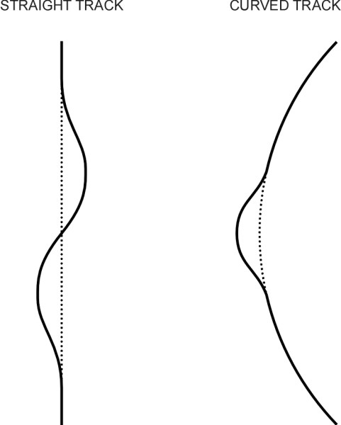
\[\begin{equation} F \quad = \quad ES \alpha \, . \, \Delta \theta \end{equation}\]In most parts of the world, the maximum range of temperature variation between the coldest night and the hottest day is of the order of \(35^\circ\) C. Imagine a track made from UIC 60 rail of cross-sectional area 7687 mm2, laid when the temperature lies at the bottom of this range. Initially, the compressive force will be zero. When the temperature reaches the top of its range there will be a compressive force equal to \(200 \times 7687 \times 0.000012 \times 35 = 650\) kN approximately. This amounts to nearly 65 tonnes. Notice that the force doesn’t depend on the length of the rail: when fully restrained it’s the same for a one-metre length as it is for a continuous rail extending from coast to coast across the USA. Now, if you place a long, thin steel rod on the ground and applied a compressive load of 65 tonnes, it will buckle. Experience shows that a straight section of railway track tends to distort into an S-shape, while a curved section will form a C-shaped kink, as shown in figure 12.
Figure 12
So how does one prevent the track from buckling? For conventional track there are two main solutions. The first is to pile up the ballast around the sleepers, so that the stones interlock and resist any tendency for the sleepers to slither off to one side. The second is to lay the track at a temperature mid-way between the two extremes likely to be encountered during its working life, which in the UK is taken as \(27^\circ{}\) C [1]. The track will then undergo compression when the temperature rises above the middle of the range, and for temperatures below the middle of the range it will actually be in tension. In practice, one can’t wait for exactly the right temperature conditions and the usual procedure is to carry out installation in cool weather and compensate by stretching the rail before fixing it to the sleepers.
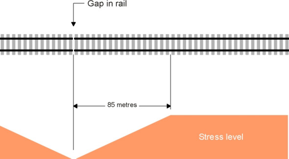
That’s fine, but there is one more problem to solve. The engineer will want a few small gaps in the rail to separate the track into manageable sections, so let us see what happens at either end of a continuous section. It’s almost impossible to anchor the butt sufficiently to resist a 65 tonne force, and instead it is left free to move. Hence the force is dissipated a little at a time through successive sleepers until it tapers off to zero. Conventional ballast can provide a frictional resistance of around 0.75 tonnes per metre of rail, so working backwards it seems that the length of rail needed at either end for the load to dissipate is 65/0.75 or roughly 85 metres (figure 13). We shall call this the ‘end zone’. In the middle section, the rail is locked in place, but within the two end zones it will move, contracting in cold weather and expanding when it’s warm. To work out how much it moves, we observe that if the sleepers were to provide no resistance, the range of expansion would be \(85 \times 0.000012 \times 35 \times 1000 = 36\) mm. On the other hand, if the butt were fully restrained, the expansion would be zero. If we assume the load in a rail is dissipated evenly among all the sleepers, the average stress and the average strain in the end zone will be half the value in the centre section, so the expansion will be reduced correspondingly by a half from 36 mm to 18 mm. If two rails are laid end-to-end, each with room to expand by 18 mm, there will be a 36 mm gap between them in cold weather. The engineer will get round this by arranging the joint at a shallow angle to the rail axis so there is no pronounced impact as each wheel passes from one section to the next.
Figure 13
Rail wear and damage
On 17 October 2000, a passenger express train travelling from London to Leeds at a speed of about 200 km/h left the track on a curve near Hatfield. The cause of the crash was a broken rail, which was thought to have cracked at the gauge corner some time previously. It emerged from the media coverage following the crash that broken rails were quite common in the UK, occurring at a rate of several hundred recorded instances per year. Cracks can arise from one of several causes, and in the Hatfield case they were exacerbated by wheel loads on the outer rail of the curve. It seems that in spite of improved materials and construction, steel rails are still vulnerable to failure, and researchers are working towards a better understanding of the processes involved. There are actually three main categories of deterioration that arise from three distinct causes [25]: profile wear, corrugations, and rolling contact fatigue. Let us look at each in turn.
Profile wear
A steel wheel exerts a heavy pressure on the rail in the centre of the contact patch. As we saw in Section R2019, the resulting shear stresses reach their peak in a narrow band a few millimetres below the surface. Since they exceed the yield point, at the moment the wheel passes overhead the steel softens, and were it not confined by surrounding material it would flow like melting butter. The impact of many wheel loads permanently changes the character of this material. The stresses distribute themselves more evenly, and some remain locked inside. The residual stresses tend to protect the surface and by raising the elastic limit, make it harder - a phenomenon known as elastic shakedown [27].
Notwithstanding the fact that it hardens with use, the upper surface of a rail is continually worn down by traffic. Sometimes the wear is quite localised. For example, on a slippery track, if the wheels of a power bogie spin out of control when a train accelerates they can make dents in the surface. More generally, the track wears because the high contact stresses weld together the tips of any projecting asperities on the wheel and rail and tear them away from the softer surface [24]. Also loose flakes of material together with grit from other sources can become wedged between the contact surfaces and act as an abrasive. Hence the rail and the wheel tread are gradually worn away towards the same profile (figure 14). Not only does this weaken the rail, but it alters the geometrical relationship between the wheelset and the rail and in doing so, affects the stability of moving vehicles.
Figure 14
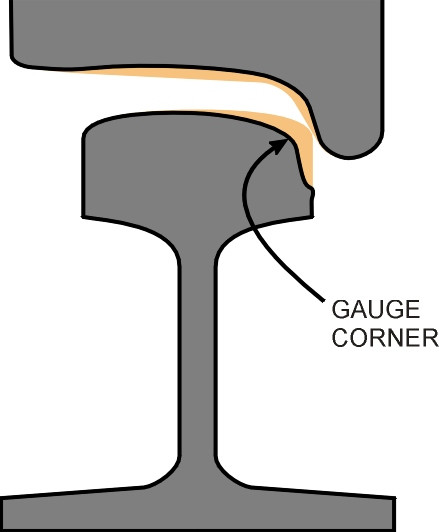
The maximum permissible loss of material across the top of the running surface is usually fixed in the range 10 to 25 mm depending on the traffic loading conditions. However, the wear doesn’t take place evenly. It tends to be concentrated at the gauge corner where the sliding contact speed and stress are higher, particularly on the outside rail on a sharp curve, so there are specified limits on the lateral wear at the gauge corner. Worn rail may be recycled for use elsewhere in light traffic, and some may last for 100 years before finally being scrapped, but nevertheless, railway operations have a considerable appetite for steel rail. For example, in the Netherlands the annual consumption is over 20 000 tonnes [7].
Development of corrugations
We have already mentioned in Section R1610 the noise that a railway wheel can make when moving at speed. When it vibrates, it becomes an efficient loudspeaker that broadcasts sound as effectively as a church bell (except that it is not very musical). The source of the vibration lies in the contact area between the wheel and the rail, where any surface roughness can trigger one or more resonant modes. One particular kind of roughness has been studied intensively by scientists and engineers since the early 1980s. It takes the form of regular waves or corrugations. They arise from resonant vibration of the wheelsets triggered by welded rail joints and other discontinuities in the rail surface. The regular pulses in wheel load downstream cause variations in wear that build up over time with the passage of traffic. It’s a kind of feedback process: the corrugations stimulate the vibrations and the vibrations in turn exacerbate wear and increase the severity of the corrugations. Similar undulations occur on a road surfaces too, but they are less common [20]. In the case of a railway, as well as creating a noise nuisance, the resulting wheel vibrations can damage wheels, suspension components, and rail fastenings.
There are six distinct causal mechanisms [17] corresponding to different modes of vibration in combination with different wear or damage mechanisms. One particular form of corrugation leads to an unpleasant phenomenon called ‘roaring rail’. With wavelengths between 20 mm and 100 mm and amplitude up to 180 \(\mu\)m, the corrugations have caused serious problems on British and German high-speed tracks. The causal process, which first gave rise to published research during the 1980s, involves two distinct mechanisms, (a) a wavelength-fixing mechanism, and (b) a damage mechanism [21]:
- A shiny layer appears on the rail surface about 5 - 10 \(\mu\)m deep, technically known as a White Etching Layer (WEL). Its chemical structure is not yet understood. In normal circumstances this layer is continually worn away and renewed from the bulk material below, but at higher speeds, small irregularities in the rail surface excite resonances in the wheel/track system.
- After a few months, small corrugations appear. The white etching layer on the peaks is harder and more brittle than the pearlitic bulk of the steel rail so the peaks have roughly twice the wear resistance of the troughs.
- The white etching layer on the peaks grows to a depth of up to 100 \(\mu{}\)m, while it is worn away in the troughs. Hence the amplitude of the corrugations from peak to trough continues to increase. This has the effect of amplifying certain frequencies [23], which creates a feedback loop so that the vibrations and the wearing action reinforce each other.
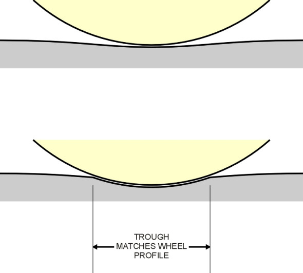
- Eventually when the amplitude reaches about 180 \(\mu{}\)m, the wheel can only just fit into a trough and growth ceases. It effectively fixes the wavelength of the troughs because no further change is possible (figure 15). This phase is termed ‘saturation’.
Figure 15
Fatigue
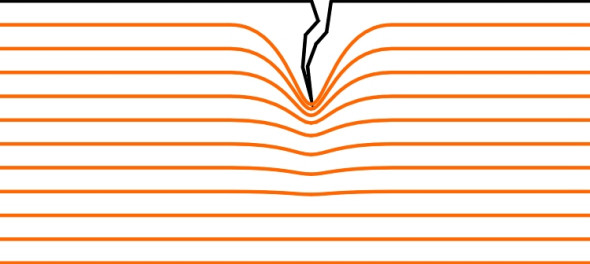
Surface damage is obvious and in principle can be treated by grinding the railhead. Fatigue damage is more insidious. It may start deep within the cross-section and remain hidden until the rail breaks. It is a curious feature of the fatigue process that even a tiny defect can lead to disproportionate consequences because of the way stresses distribute themselves in a solid body. The pattern of stress can be pictured like the flow of water in a river. Where the river bed narrows, the ‘streamlines’ are squeezed together and the water moves more quickly. Similarly, any constriction in a metal body will squeeze the lines of force more closely together, which is another way of saying that the stress locally increases (figure 16). And like the water in a river, which piles up around any obstructions on the river bed, the lines of stress in a solid body under load become more concentrated around any flaw in the material. For example, a small circular hole in a flat plate under tension will raise the stress locally by a factor of three [34]. Re-entrant corners make matters worse: the smaller the radius of the corner, the higher the stress. If the stresses were equitably distributed throughout the cross-section, there would be no problem, but in practice the stresses tend to pile up around a slot or a nick in the surface and a crack ensues (figure 17).
Figure 16

Figure 17
Potentially, fatigue is a widespread phenomenon because metals are used everywhere: in home appliances, in buildings, and in manufacturing industry. Small cracks and defects are common, but they rarely lead to failure because the stresses are small. A modest load has little effect, and if the loading regime is tailored to suit the fatigue resistance of the material plus a suitable margin of safety, a metal component will last almost indefinitely in service. This is why fatigue was almost unknown, or at least not well understood, until the beginning of the twentieth century. But fatigue cracking is extremely sensitive to the applied load and the number of load cycles. The likelihood of a crack being formed escalates rapidly when the load rises above a certain level, and it grows in length each time the load is applied and removed (or reversed). In certain circumstances, once started, the crack continues to elongate, being continually pulled apart by the progressively more intense stress concentration at its tip (figure 17). Failure is then inevitable - it’s just a matter of time.
It was in the transport field that fatigue problems first came to public notice, because vehicles are particularly vulnerable. If you are building a vehicle, you will make it as light as possible, and other things being equal, this will lead to high stresses. And when a vehicle moves, it suffers vibrations and impacts that make the stresses oscillate over a wide range. Consequently, over the last hundred years there have been failures, some of them in mysterious circumstances with little debris left behind to show what happened. They include, for example, the abrupt disintegration at sea of ‘Liberty’ cargo ships built during the Second World War to bring supplies to Europe, and the disappearance in flight of three de Havilland Comet jet airliners during the 1950s. Nor is fatigue restricted to metals: it occurs within the mix of bitumen and stone chippings that make up the bulk of a modern highway, where it is the main cause of road wear. As each vehicle passes overhead, the wheels deliver pulses of energy that elongate any small cracks or cavities in the bitumen matrix. The damage is highly sensitive to the weight of the vehicle, so that heavy lorries are responsible for a disproportionate amount of road wear while cars have almost no perceptible effect. In quantitative terms, road wear is proportional roughly to the fourth power of the wheel load (see C1602). A broadly similar pattern occurs with steel rails [32].
Here we encounter a paradox. Until recently, broken rails were mostly attributed to flaws inside the material coupled with heavy wheel loads. One particularly common defect, the tache ovale, was caused by a microscopic hydrogen bubble created during the manufacturing process. But it has largely been eliminated by improved quality control. Why then has the incidence of broken rails increased? The reason has to do with different types of fatigue crack all of which come under the general heading of rolling contact fatigue. They have exotic names like head checks and gauge corner cracking [3] [12] [26], and they arise in areas where the contact stresses are highest, namely towards the inside corner of the outer rail on curves. Too small to be seen with the naked eye, they start on the rail surface as small cracks less than 2 mm long and 0.5 mm deep, aligned to weaknesses in the crystal grain structure [13]. In the past, when the steel from which the rail was made was appreciably softer than it is today, locomotives were a good deal heavier and their wheel flanges would press against the inside face of the rail and wear away the cracks before they could cause any trouble. Nowadays, the vehicles move faster and the wheel flanges continue to generate high stresses in the gauge corner. But because the rail is harder, the cracks no longer wear away before reaching critical size. Many railway operators remove them by grinding the rail surface at intervals via a process known as Mill Head Treatment (MHT) [18], but it isn’t a complete cure [21].
Conclusion
We started this Section by wondering how to build a track that would support a rolling vehicle so its wheels wouldn’t sink into the ground. Experience has shown that neither the wheel nor the running surface can be considered in isolation - it is the combination that matters. After centuries of experiment, engineers have arrived at two different solutions. The first is a steel wheel running on a steel rail: a hard material in contact with a hard surface. The second is a pneumatic tyre running on concrete: soft-on-hard. From the perspective of the nineteenth century, the hard steel wheel running on a hard steel rail seemed the obvious way forward because no-one knew how to make a pneumatic tyre. Today, we know that either solution can be made to work well in its own particular niche. The steel wheel on steel rail has three advantages: it is simple, it can carry roughly twice the load, and it can do so at two or three times the speed of a mass-production pneumatic tyre. However, the wheel load is transmitted to the rail through a small contact area, and the resulting stresses wear away both the wheel and the rail surface. You can improve the quality of the steel by making it harder but this doesn’t work as well as you might think. The harder the steel, the smaller the contact area and the greater the stress: it’s a question of diminishing returns.
Web site
Thermit welding process: http://www.thermit-welding.com/thermit_welding_process.php, accessed 03 December 2014.
Further reading
LEWIS, R and OLOFSSON, U (editors) (2009) Wheel-rail interface handbook. Cambridge: Woodhead Publishing Ltd.