R.1114
Railway suspension
‘The railway train running along a track is one of the most complicated dynamical systems in engineering’
A H Wickens [41]
To travellers in the nineteenth century, the arrival of the railways with their smooth steel rails must have seemed a blessing. But in reality a steel rail is not perfectly smooth, and unlike the rubber tyres on a car, steel wheels trace out every imperfection in the surface. Trains rumble, and just like road vehicles, they need suspension springs and dampers to filter out vibrations. The springs have other tasks as well. While an automobile suspension is essentially one-dimensional (the wheel moves up and down), railway suspension is three-dimensional. The wheel must absorb lateral jolts that occur when the flange hits the inside shoulder of the rail, and allow a degree of fore-and-aft movement so the wheelset can ‘steer’ round curves. Finally, the springs keep each wheel in contact with the track in places where it dips below its nominal alignment, which helps to prevent the wheelset jumping the rails. In what follows we’ll describe the various forms of disturbance in more detail and how the suspension is configured to deal with them.
The suspension cascade
The purpose of a railway vehicle suspension is to provide flexibility, so that whenever the wheel is deflected by some irregularity in the track, the body floats along with the minimum possible disturbance to passengers and cargo. It’s the same idea as the one we pictured earlier in Section C1114 in relation to road vehicles. Flexibility is provided at different levels within the suspension system. For example, passenger coaches have two sets of springs and dampers: the first set, which makes up the primary suspension, connects the wheelsets to the bogie frames. It is designed to filter out higher-frequency disturbances in the vertical direction and to permit a little lateral movement together with fore-and-aft movement at each axle-box so the wheelset can ‘steer’ on curves. The second set of springs and dampers, the secondary suspension, supports the coach body on the bogie frames. It deals with relatively low-frequency disturbances, isolating the passenger cabin from vertical bumps and lateral jolts over rail joints, turnouts, and poorly aligned track (figure 1).
Figure 1
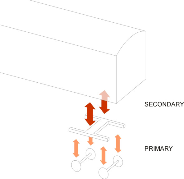
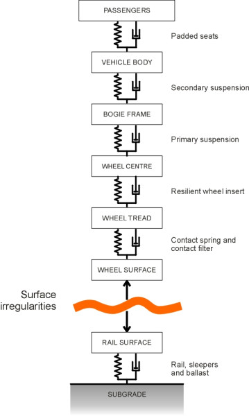
The various levels of suspension can be pictured as forming a ‘cascade’ as shown diagrammatically in figure 2. Each level is designed to handle a specific frequency range, with the higher frequencies allocated mainly to the lower levels. Freight wagons usually have only one set of springs and dampers, which can be located either between wheelsets and bogie frame, where it is sometimes referred to as ‘axlebox suspension’, or between the bogie frame and the wagon body (‘central suspension’). Some have both [23]. In addition to the springs and dampers, figure 2 shows other components that flex elastically whether intentionally or otherwise, and we’ll deal with these separately later on.
Figure 2
Roughness input
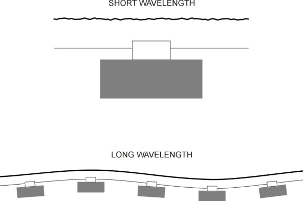
Before going any further, let’s consider how the various disturbances arise. Roughness in the rail surface occurs on several different scales of measurement: some of the peaks and troughs are only a millimetre across while others extend for a metre or more along the rail (figure 3). They can all be pictured as waves. If you imagine a wheel rolling along from one peak to the next, it is clear that a wavelength of 1 mm will make it bob up and down at a high frequency, while a longer wavelength will lead to a lower frequency. The important wavelengths range from 5 mm to 500 mm [36], not very different from the wavelengths typical of a concrete road. The roughness profile can conveniently be represented in the form of a power spectral density curve, and as is the case with highway surface roughness (see Section C1603), curves of this kind reveal a broadly consistent relationship between wavelength and amplitude; at short wavelengths the peaks are not very high, but their amplitude increases with increasing wavelength. Compared with a road surface, however, the amplitudes are smaller across the whole spectrum.
Figure 3
The irregularities arise from at least four distinct sources. The first, which applies at the shortest wavelengths of the order of 5 mm, is caused by imperfections in the manufacture of the rail together with scratches and other localised forms of wear. The peaks are tiny, having an amplitude of around 1 \(\mu\)m. The second is associated with rail corrugations at wavelengths of the order of 50 mm and more. As previously discussed in Section R1605, they develop as the track wears over time, and their amplitude is much higher, up to 180 \(\mu\)m on high-speed passenger lines [12] [14] and more on lines carrying heavy freight traffic [9]. The third category has to do with discontinuities in the structure of the rail: gaps in the surface at turnouts and crossings, together with imperfections in alignment. Some of the imperfections, of the order of 500 mm in wavelength, arise in a surprising way. In continuously welded rail, when the butt ends of neighbouring sections are welded together, the process often leaves a kink barely perceptible to the human eye, but one that delivers an appreciable impulse to the wheels of a fast-moving train, either vertically, or horizontally, or both. Also the rate of wear in the vicinity of the weld is uneven so that over time, the surface loses its smooth alignment [35]. The fourth and final category has to do with the trackbed structure. There is unevenness in the way the rail deflects underneath the vehicle wheel, the deflection being larger when the wheel passes across the unsupported section between neighbouring sleepers than it is at the sleepers themselves. This unevenness injects regular impulses at ‘sleeper passage frequency’ [5].
And unlike the wheel of a road vehicle, the railway wheel itself is responsible for some of the roughness input. Manufacturing imperfections together with wear or damage over time mean that the tread surface is not entirely smooth. In fact, the tread can become corrugated just like the rail surface: wheel corrugations were first discovered on the vehicles of the Deutsches Bundesbahn many years ago [34], caused largely by the brake blocks which acted on the wheel treads to create roughness at wavelengths of the order of 60 mm [37]. Other types of wear can distort the circular profile on a larger scale [16]. The so-called ‘polygonal wheel’ was a factor in the Eschede disaster in June 1998 [15], in which the fragmentation of a single steel tyre caused the bogie of a high-speed train to derail. The derailed coach carried others with it; together they collided with the supports of a concrete bridge and caused it to fall on top of the train.
So far, we have considered only vertical impulses acting on the suspension. But, unlike an automobile, a railway vehicle is buffeted by lateral impulses too, which occur when a wheel flange collides with the inside face of the rail. They produce a sideways jolt and consequently a railway vehicle needs some form of lateral suspension, or at least a degree of elasticity, to reduce the impact. Some of the impulses arise from inaccuracy in the rail alignment, such as a kink in a welded rail joint, while others are caused by discontinuities at turnouts, where the wheel meets the toe of a switch-blade, which is never quite tangential to the stock rail (see Section R1603). But potentially the most serious impacts arise from unstable behaviour of the vehicle itself. The phenomenon known as hunting, a zig-zag motion to which all rail vehicles are prone when they are driven above a critical speed, is dealt with separately in Section R0418.
The contact filter and contact spring
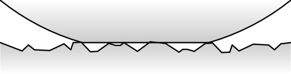
To summarise, the rail presents a rough surface that forces the wheel to deflect up and down and from side to side, tracing out irregular motions across a wide frequency range. We can now examine what happens to the vibrations as they pass upwards into the vehicle through the suspension cascade. To begin with, just as in the case of a pneumatic tyre (see Section C1114), the contact patch, which is about 10 mm across, bridges across roughness in the rail surface (figure 4). The bridging process has been described as a contact filter that effectively smoothes over the shortest wavelengths so that they are removed from the input spectrum. Also, the wheels themselves are slightly flexible: the metal deforms elastically like a very stiff spring and absorbs a small degree of roughness. Unlike that of a conventional spring, the stiffness of the ‘contact spring’ isn’t constant but rather increases with increasing deflection. Figure 2 shows the contact filter and the contact spring together as the first ‘layer’ in the suspension system. At the next level, it shows a third mechanism through which high-frequency vibrational input can be reduced, by separating the tread from the main body of the wheel disk with a resilient layer as described in Section R1610. This device is often used on trams.
Figure 4
Primary suspension
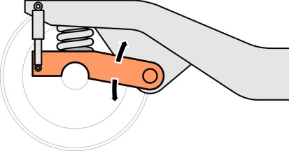
Now we come to the primary suspension proper. It usually involves steel springs together with some form of damping located between the wheelset and the bogie frame. The aim is to allow the wheelset to move up and down relative to the frame, and one of the simplest ways of doing this is to house each bearing in an axle-box that is free to slide up and down between two vertical guides - traditionally known as horns (figure 5). On older vehicles the springs are steel leaf springs, made up in layers that slide over one another when they flex, which provides a degree of damping. This is the system inherited from early steam locomotives. But it is not ideal because the axle-box presses hard against the horn under braking (figure 6). This has three consequences: first, the pressure increases the rate of wear of the sliding surfaces, secondly, the axle-box tends to jam under pressure so the springs can’t do their job, and thirdly, it creates tensile stresses at the base of the horn that can lead to cracking under repeated loads.
Figure 5
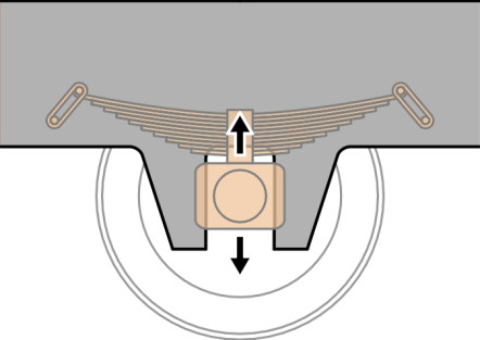
Figure 6
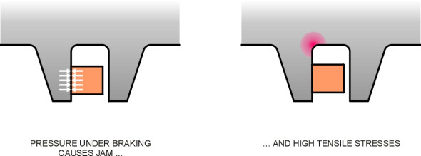
Figure 7
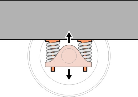
Other methods are used today. One is a modification of the horn: the axle-box is attached to a collar that slides up and down on a pair of cylindrical stubs bolted rigidly to the bogie frame as shown in figure 7. Another is the rubber shear block, built from alternate leaves of rubber and steel. There are several variants of this idea, for example, the cylindrical form as used on the TGV Y2-30 bogie [19], and, in combination with steel coil springs, on the Shinkansen series 300 bogie, while chevron rubber blocks appear on the Swedish X-2000 [25] as shown in figure 8. As well as vertical movement, a rubber shear block provides some lateral flexibility which can improve the quality of the ride. The third alternative is a coil spring with the axle constrained by one or more connecting links to the bogie frame. A simple trailing arm is shown in figure 9. This is widely used on suburban and intercity passenger trains, in conjunction with a hydraulic damper similar in principle to the dampers found on lorries and cars. Finally, it should be noted that each system provides for motion in the vertical direction but also a much smaller freedom of movement fore-and-aft so the wheelset can steer round curves. This additional freedom can be provided through a flexible axlebox mounting.
Figure 8
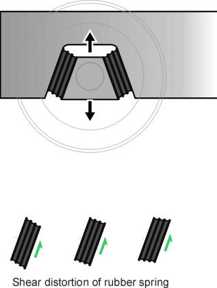
Figure 9
Secondary suspension
On almost all passenger coaches and some freight wagons today, the bogie carries the weight of the vehicle body through an additional set of springs and dampers known as the secondary suspension that forms the final stage in the suspension cascade (or the penultimate stage if you count the passenger seats as part of the suspension). The secondary suspension provides both vertical and lateral flexibility, so the bogie can move from side to side relative to the vehicle body in response to a lateral kink in the rail alignment and thereby reduce the impact on passengers and cargo. Secondary springs handle disturbances in the lower frequency range, and the softer the springs, the better. Their natural frequency is about 1 Hz, about the same as an automobile. But there are two practical constraints. Firstly, a railway train consists of several connected vehicles, and the floor heights of any two neighbouring vehicles must remain broadly consistent regardless of any disturbances [28]. Secondly, the design of a railway track allows for only a small clearance around the vehicle body and a large deflection can allow the vehicle body to sweep out a larger cross-section that would otherwise be the case, fouling trackside furniture and tunnel walls (see Section R1604).
Figure 10
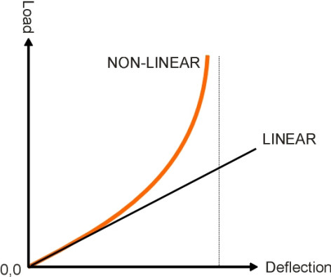
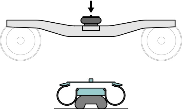
In practice therefore, the spring system must be non-linear, that is, it becomes stiffer towards the end of the stroke (figure 10). For many years coil springs have been the preferred choice for both passenger vehicles and freight vehicles, but they have approximately uniform stiffness throughout most of the suspension stroke so that each increment of load yields a proportional increase in deflection. Without modification, they are unsuitable for freight wagons for reasons we’ll mention later. As far as passenger vehicles are concerned, air suspension is now preferred. We have already mentioned air suspension in connection with heavy lorries (Section G1114). Although it is more complicated than coil spring suspension it is much lighter, and can be configured to keep the vehicle automatically at a constant height above the rail irrespective of load. When applied to a passenger train, it helps to maintain a consistent floor height between neighbouring coaches and also helps with docking alongside station platforms. The stiffness can be varied under microprocessor control, and the airbag can accommodate a degree of lateral deflection as well as vertical deflection (figure 11). It can also be adapted to provide damping. Finally, like road vehicles, all railway vehicles are provided with bumps stops as a last resort to limit suspension travel [32].
Figure 11
We should perhaps complete this brief review of the suspension cascade by mentioning the vehicle body and passenger seats. Both provide an additional ‘layer’ of springing, advantageously so in one case but not in the other. Let’s take the vehicle body first. A passenger coach can be likened to a hollow beam spanning between two bogies. The beam is not entirely rigid, and in fact a lightweight body shell is liable to flex up and down or from side to side between the bogie supports. It has a resonant frequency around 10 Hz [39], and vibration at this frequency can double the discomfort perceived by passengers seated in the middle of the cabin [31]. On the other hand, the springing in a passenger seat squab effectively filters out some of the disturbances that work their way through the primary and secondary suspension and reduces the amplitude of vibrations transmitted to the passenger’s spinal column. This completes the fifth and final layer of the cascade as shown in figure 2.
The railway bogie
The design of a railway vehicle that will run safely at high speed is a technical challenge that has taken more than 100 years to overcome. At the heart of the problem lies the twin-axle bogie, usually hidden under the vehicle body where it’s not easy to see what is going on. In the next few paragraphs we’ll consider why bogies are necessary and what forms they can take, and then go on to describe some standard designs.
Function
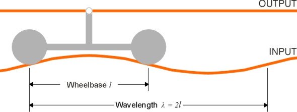
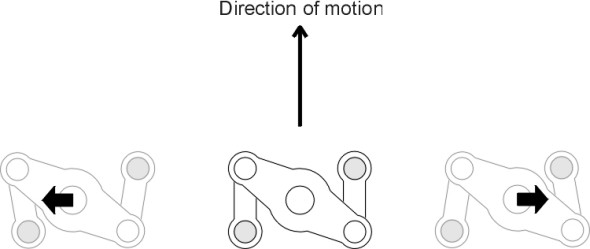
The main purpose of a bogie is to provide flexibility in ‘steering’ so the wheels can align themselves more closely with the track when the train goes round a curve (figure 12). As we’ll explain in more detail in Section R0415, steering reduces the tendency of the leading outside wheel to grind against the inner face of the rail or climb over the top. Less often mentioned is the fact that the bogie helps to even out the impacts caused by vertical irregularities in the track [11]. In effect, the central pivot ‘takes the average’ of the deflections at the two axles: if on a level track the leading wheelset rises over a bump of height h while the trailing wheelset remains unaffected, the deflection at the bogie pivot will be only \(h/2\). If we picture roughness as a superposition of sine waves, we can go a little further and analyse the effect as a function of wavelength. For certain wavelengths the analysis is easy. For example, at a wavelength equal to the bogie wheelbase, there is no advantage because both wheelsets rise and fall together (i.e., in phase) and the amplitude at the bogie pivot is that same as the amplitude at the rail surface. At the other extreme, when the wavelength is equal to twice the bogie wheelbase the wheelsets are 180\(^\circ\) out of phase. In this case, the movement at the bogie pivot is zero and the disturbance is completely neutralised (figure 13).
Figure 12
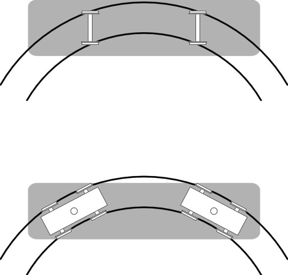
Figure 13
At a more general level, the bogie facilitates railway operation, because it simplifies vehicle maintenance. If a unit is worn or damaged, the vehicle body can be lifted clear in the workshop and the bogie removed so the maintenance crew have relatively easy access to the suspension components, brakes, and transmission. Meanwhile it is replaced by a refurbished bogie so the vehicle can return to service. However, the bogie has one major disadvantage. It adds significantly to the vehicle weight: for example, the two bogies together account for 40% of the unladen weight of a typical freight wagon [4]. And the bogie contributes to unsprung mass potentially at more than one level within the suspension cascade. Let’s look at the primary level first.
Unusually among land vehicles, each pair of wheels is rigidly joined together by an axle that rotates with the wheels and keeps them turning at the same speed. This is an essential part of the mechanism that helps the bogie to steer itself along the track, and we’ll say more about this process in Section R0415. But in consequence, the wheels and axle together constitute a large unsprung mass, each wheelset typically weighing as much as a family car: roughly 1800 kg in the case of a Thalys high-speed train [7]. The inertia is considerable, and since there are no pneumatic tyres, the wheels inject strong impulses into both the suspension and the track when they encounter irregularities in the rail surface. On a power bogie, the unsprung mass of the wheelset is greatly increased if it supports an electric motor. At one time it was common practice to suspend the motor from two attachment points. The first was a hinge on the bogie cross-member, which secured the rear of the motor casing, while the other end was borne by the axle. The extra weight on the axle led to a poor quality ride together with a great deal of track wear.
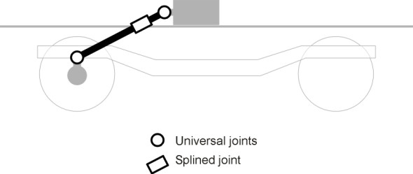
Now let’s look at a higher level. For a passenger vehicle having both primary and secondary suspension, almost the whole of the bogie contributes to unsprung mass at the level of the secondary springs. Although this has less effect on ride quality than unsprung mass further down the cascade, it is not ideal from the point of view of track wear, particularly in the case of a power bogie that is weighed down by one or more electric motors. It is good practice to move the motors as far as possible up the cascade, and on today’s high speed trains each motor is usually suspended from the vehicle body and linked to the wheelset through a Cardan shaft (figure 14).
Figure 14
Bogie structure
The framework of a conventional bogie takes the form of a letter ‘H’ with the pivot at the centre of the cross-piece. At the four corners, the frame is supported usually on primary suspension springs that transmit the load downwards to the wheelset bearings within which the axles rotate. Let’s concentrate on one of the wheelsets, say the leading wheelset. The bearings are usually positioned outboard of the wheels, supporting a bogie frame that is wrapped around the outside as shown in the upper diagram of figure 15. Wheel bearings are potentially a source of trouble on railway trains and the outboard position makes them easy to inspect. They are also easy to dismantle so the wheelset can be removed and if necessary, replaced. But this is not the only possible arrangement: the bearings can be located inboard with the bogie frame lying between the wheels as shown in the lower diagram of figure 15. Inboard bearings make the frame lighter and more compact, and this configuration is sometimes used on local passenger trains and trams whose modest travel speed is unlikely to result in bearing failure.
Figure 15
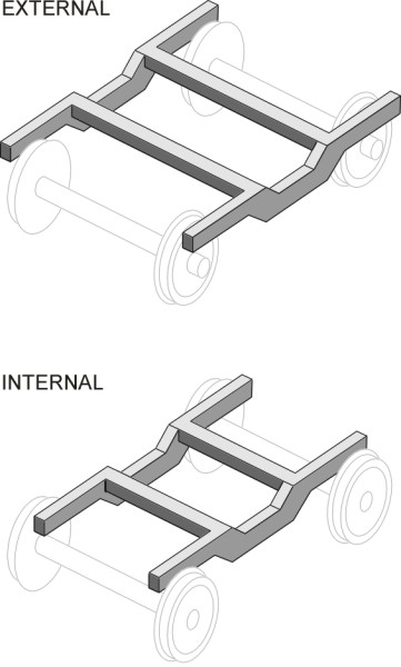
Figure 16
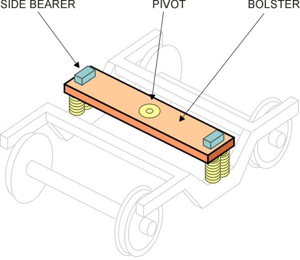
Now let’s shift attention to the secondary suspension, which lies at the next level in the suspension cascade, between the bogie and the vehicle body. There are essentially two ways to mount the body springs. In a conventional layout, they don’t support the body directly, because they would be distorted every time the bogie swivelled on a curve. Instead, they support an intermediate pad or bolster that is free to move up and down but swivels with the bogie on curves (figure 16). The car body rests on the bolster partly at the central pivot and partly on two greased blocks called side bearers that permit sliding motion and at the same time keep the body upright. Shortly we shall see how on modern vehicles, ‘flexi-coil’ springs or air springs can be designed to tolerate distortion so the bolster isn’t needed.
In the centre of the bolster (or in the centre of the H-frame on a bolsterless vehicle) is located the pivot. The pin is usually bolted to the vehicle body and projects downwards into a housing in the bogie frame. It doesn’t need to carry much weight, and nor does it need to be a tight fit. In fact there is usually a gap between the pin and the inner diameter of the housing, which allows the bogie to deflect momentarily relative to the body when it encounters a misalignment in the track. Movement is controlled by springs or wedges that encourage the coach body to settle in a central position when there are no lateral forces acting on the wheels, so that the pin only comes into contact with its housing during extreme impacts. This is the lateral suspension we referred to earlier. Ideally, longitudinal movement should be prevented, and this can be done by connecting the bogie and the vehicle body with a longitudinal ‘traction rod’, or alternatively through a Watts linkage as shown diagrammatically in figure 17.
Figure 17
On railway vehicles everywhere, you will see variations on the basic H-structure together with springs and dampers arranged in a variety of ways. There is no ‘standard’ arrangement. Some designs reflect national traditions while others reflect varying needs; for example, the size of the load carried and the operating regime of a freight wagon are very different from those of a high-speed passenger coach. You can find more information on different types of bogie including drawings and diagrams in [18] and [33]. Here we shall choose a few of the most widely used configurations and try to explain how they work.
Passenger coach bogies
We’ll begin with passenger bogies, which are more complex than the bogies used for freight wagons. The first is the swinging link bogie. It is constructed to allow the coach body to swing from side to side so it is insulated from lateral impacts delivered to the bogie by kinks in the track. The whole of the secondary suspension is seated on a plank that is slung laterally across and underneath the bogie frame as shown schematically in figure 18. The plank hangs from four links so the body settles naturally in a central position on a straight track but is free to deflect sideways on a curve [20]. Fore and aft movement is constrained by traction rods (not shown in the Figure). The swinging links are inclined at an angle to the vertical so that any sideways deflection has the effect of tilting the plank slightly, which helps to counteract any tendency for the body to roll outward under centripetal force (figure 19). Together with the plank and the bolster across the top, they act geometrically like a four-bar linkage (the linkage shown in figure 17 above is a different four-bar configuration known as the Watt’s linkage: both are related to the Ackermann steering linkage commonly found on road vehicles as detailed in Section C0504). Over several decades the swinging link suspension arrangement has been used for passenger coaches, many of which are still in service. However, it embodies a relatively large number of moving parts which together raise the overall weight of the bogie, and which require regular lubrication.
Figure 18
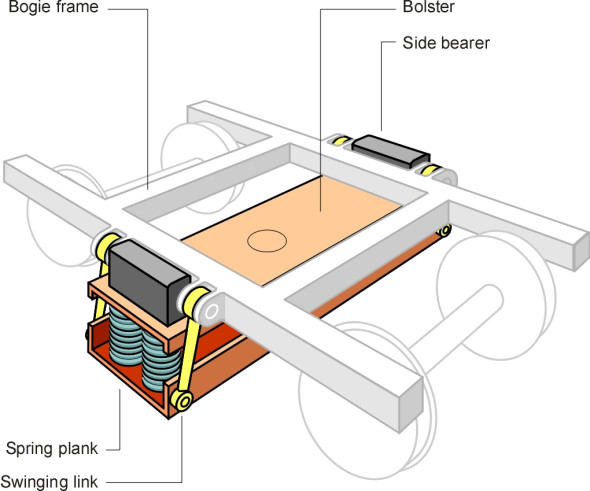
Figure 19
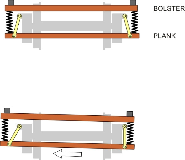
Figure 20
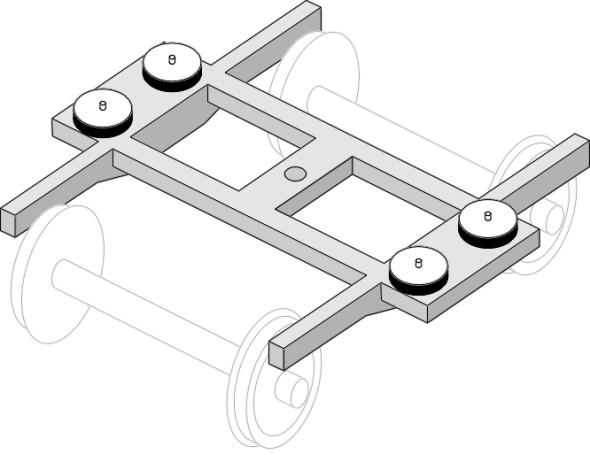
Today, air suspension is preferred because it provides a smoother ride. Air springs are usually mounted on what is sometimes called a bolsterless bogie as shown in figure 20, which compared with other types has a much lighter structure with fewer moving parts. The bolster is no longer needed because the flexible envelope of an airbag can accommodate distortion when the bogie swivels, so the airbag can be mounted directly on the bogie frame. There is scope for lateral movement through the flexible inserts within the central pivot, while longitudinal movement is more tightly constrained, with longitudinal forces transmitted through traction rods, or through some other linkage. Well-known examples are the Italian ETR-500 bogie [21] and the Japanese Shinkansen Series E2 bogie [22].
Freight car bogies
In larger countries such as China and the USA, freight trains account for most of the rail traffic, and freight wagons vastly outnumber passenger coaches. They operate in remote areas, often travelling at low speed over poor quality track. Inspecting a freight train is no easy task, and once it is under way, the driver can’t see whether the wagons are running smoothly. So by comparison with passenger bogies, freight bogies must be simple, reliable, rugged and cheap. Usually, there is only one ‘level’ of suspension: the primary and secondary springs are combined into a single set.
In Europe, the most common type is known as the Y25 [26]. It has a rigid H-frame, with steel coil springs located between the axle-boxes and the bogie frame (figure 21). The springs are compound springs designed so their stiffness increases with deflection. This is a characteristic feature of freight bogies, which must adapt to a wide range of loading conditions. When fully loaded, a freight wagon weighs up to five times as much as it does when empty, and unless the spring is somehow stiffened, the vehicle body tends to sink onto its bump stops so the available stroke is greatly reduced or indeed there is no effective suspension at all [24]. This is a problem that also occurs with heavy lorries. In principle it can be cured by fitting the wagon with very stiff springs, but when the wagon is empty, it will bounce: if a wheel encounters a misalignment or kink in the track it can lift off the rail surface and derail the bogie. As with a heavy lorry, the solution is a spring that becomes stiffer as it deflects, and this can be achieved - if somewhat crudely - by enclosing a stiff coil spring within a softer spring. When the wagon is empty, the outer spring carries the whole load; it provides a relatively low stiffness and a smooth ride with little risk of derailment. The inner spring does not come into play until the wagon is loaded and settles on its suspension, at which point the load is shared with the inner coil.
Figure 21
Figure 22
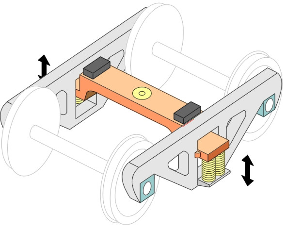
Figure 23
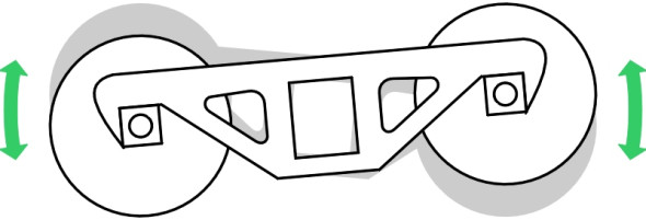
Figure 24
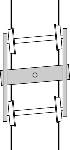
But world-wide, the most common type of freight bogie is the ‘three-piece bogie’ (figure 22). Examples of the three-piece bogie are the Russian type 18-100 bogie and the American Barber [26]. The weight of the whole assembly including wheelsets comes to about 4 tonnes [10]. As you might expect, it is made up from three separate pieces: a cross-piece and two side frames, each of which is cast in solid steel. The springs are located between the cross-piece and the side frames. The three pieces are not actually welded together, and as one author puts it, the standard US 3-piece bogie is ‘held together only by gravity’ [2]. Each side frame is slotted onto the cross-piece and held in place by retaining lugs, but there are appreciable gaps between the contact surfaces, so the side frames can move up and down and also pitch independently to even out the wheel forces on twisted track (figure 23). While the three-piece structure is easy to cast and assemble it can distort in plan so that the wheels don’t align accurately with the rails (figure 24). Some versions are fitted with cross-bracing to prevent this [40]. As with the Y25 bogie, the springs are nested to give variable stiffness with deflection so the same units can be used on cars of all weights and sizes, loaded and unloaded [1]. Being limited by the need to maintain a roughly constant height of coupler between neighbouring cars, the static deflection under maximum load is usually no more than 100 mm, rather less than a heavy lorry.
Damping takes place through a friction wedge mechanism. On either side of the bogie, the crosspiece engages with two wedges that are forced against the side frame, and the friction between the two provides resistance to vertical deflection and therefore damps the motion. Since the contact force increases with the weight of the vehicle body and its contents, effectively the damping - like the stiffness of the springs - increases with the load.
Suspension behaviour
One can think of a vehicle suspension system as a black box that receives a signal, the input, and transforms it into another signal, the output. The input is the motion of the wheel rim, which is jolted up and down as it passes over bumps and hollows in the track surface, and the output is the movement of the vehicle body. The input is not a single frequency but many frequencies superimposed: they range from low frequencies associated with bumps in the rail alignment several metres long, to very high frequencies associated with tiny imperfections in the running surface and the wheel tread. The suspension is designed to operate on each of the input frequencies and absorb or filter them out so that the amplitude of the output body vibration stays within acceptable limits.
The track moves as well
When a car travels along a motorway, the pavement flexes slightly under each wheel because, like any physical structure, it is not totally rigid. But the deflections are small compared with the size of the roughness, so that for practical purposes the surface profile doesn’t change when the vehicle passes over it: the road itself is the input ‘signal’. A railway track on the other hand is more flexible and the surface irregularities are small, so when moving at speed, the wheel reacts against the track and momentarily changes the profile. When it encounters a peak of height h, say, it doesn’t climb up the peak and down the other side like a beetle crawling over a stone. Instead, it rises through a distance less than h because the track sinks under the dynamic impact of the wheel load. Similarly, when it encounters a trough, the wheel deflection is less than the depth of the trough. Hence from the point of view of the vehicle suspension, the input signal is not the elevation of the rail surface as measured in the absence of the train. The process has been described as follows: imagine the roughness as a thin, wrinkled sheet sandwiched between the wheel and track [6] [38]. The sheet is pulled between them so they both deflect. As shown earlier in figure 2, impulsive loads are transmitted both downwards into the track and upwards into the wheelset, causing both to vibrate.
Modelling the system
One can go a long way towards understanding a suspension system by looking at the output (the amplitude of vehicle body vibration) that arises from any particular input (track roughness of a given frequency). By repeating the exercise across a wide range of input frequencies one can build up a response curve that describes how well the suspension functions over the range of conditions likely to be found on real track. This is what we did for the quarter-car model in Section G1115, where we pictured the automobile as four separate masses, each corresponding to a quarter of the vehicle and each connected to a wheel by a spring and damper. It emerged that (a) at very low frequencies the up-and-down motions of the body mirrors the up-and-down irregularities in the road surface, (b) at frequencies close to the natural frequency the body vibrations increase sharply, amplifying the roughness in the road, while (c) at higher frequencies, the body motions are greatly reduced. If one takes into account the elasticity of the tyre, which behaves like an auxiliary spring in series with the suspension, the maths is more complicated but one can still work out a formula for the response and plot it as a function of input frequency.
At first sight, the four-wheeled bogie is not very different from an automobile, and we can in principle treat it the same way. But there are too many complications. First, the wheels are connected together in pairs and therefore the four ‘quarters’ of the bogie can’t really be considered separately. Second, the suspension has lateral flexibility that allows the body to move from side to side relative to the bogie. Third, as we have just seen, far from being a fixed base or reference point, the track itself is part of the system, moving up and down beneath the train. For passenger coaches, there is the further complication of the secondary suspension system, and if we want to take into account resilience in the wheels we must add yet another dimension. The system is too complex to be analysed using pencil-and-paper, and the designer must turn to the computer to work out how the vehicle is likely to behave. In the past three or four decades, research teams in different countries have developed a range of computer programs, each designed to model a certain aspect of behaviour, such as hunting on a straight track (Section R0418), or flange contact on a sharp curve (Section R0415). But more recently, software packages have emerged that can deal with almost any kind of vehicle in almost any situation.
The underlying principle is straightforward. A vehicle can be represented as a multi-body system (MBS), that is to say, a collection of bodies joined by springs and dampers. Each ‘body’ is a physical object having mass, while the springs and dampers do not. For example, the tyre of an automobile can be pictured as a ‘body’ joined to the wheel by a notional spring and damper. The wheel in turn is joined to the vehicle structure through a series of suspension links, all of which can be pictured as distinct ‘bodies’ that are connected to their neighbours through flexible bushes that are meant to absorb high-frequency vibrations. Each bush works like a tiny spring-and-damper combination. The same principle applies to a railway vehicle, whose wheelsets, bogie frames, bolsters and passenger cabin are represented as separate bodies connected by springs and dampers as shown earlier in figure 2. Some of the springs are merely rubber inserts, while others are steel coil springs or airbags. The equation of motion of each body takes the form of a second-order partial different equation, and the numerical parameters that form the constants in the equations are supplied in the form of matrices. Some of the equations, in particular those that delineate bodies with hysteresis properties such as hydraulic dampers, are non-linear. Hence the equations can’t be solved analytically and a numerical procedure is needed instead. A comprehensive review of MBS procedures applied to railway vehicles appears in [30] together with sample results.
Over the years, studies have been carried out on many design prototypes to predict their likely performance, and it’s not possible to give a simple account here. For any individual vehicle, multi-body systems analysis can reveal undesirable behaviour, such as a resonance likely to produce excessive vibration at a particular running speed, for example the flexing of the whole coach body as described earlier. But the most important problems are usually concerned with the ability of the vehicle to run safely at high speed, and MBS analysis has proved useful in diagnosing likely difficulties with steering on curves, and with hunting on straight track.
Suspension behaviour
It’s interesting to compare the characteristics of a typical railway suspension with that of a road vehicle. The comparison is not entirely straightforward but we can use two suspension parameters that between them largely determine how the vehicle responds to irregularities in the track: (a) the natural frequency, and (b) the damping ratio. In the case of a two-stage railway suspension we must combine the values for the primary and secondary stages into a single figure. The method is described in the Appendix, where figures are given for a particular Thalys train. For each wheel, the overall spring stiffness comes to about 400 kN/m. This is about 20 times stiffer than that for a typical passenger car wheel (around 20 kN/m), as indeed it must be because the railway wheel is carrying a much heavier load: if we take the Thalys wheel load as 8 500 kg, and the saloon car wheel load as 400 kg, the ratio of wheel loads is also roughly 20 to 1. So it looks as if the springs in some sense might be comparable, and this turns out to be the case if we think in terms of the natural frequency of the suspension, given by
(1)
\[\begin{equation} \omega \quad = \quad \sqrt {\frac{k}{M}} \end{equation}\]where \(\omega\) is expressed in rad/s, \(k\) is the spring stiffness in kN/m as before, and \(M\) is the wheel load in mass units, i.e., in kilograms. If the ratio of \(k\) to \(M\) for a railway passenger coach is roughly the same as the ratio for an automobile, we expect the natural frequencies to be roughly the same too. In fact for a wide variety of rail passenger coaches the natural frequency lies in the range 0.9 to 1.2 Hz [27], roughly the same as the natural frequency for a passenger car.
And what about the damping ratio? A suspension system needs effective damping to prevent unpleasant oscillations when the input frequency matches a resonant frequency within the suspension. The value must be large enough to prevent sustained bouncing of the coach body on its springs, but not so large that the dampers short-circuit the springs and pass on to the vehicle body a great deal of high-frequency vibration. Here again, if we take into account the greater vehicle weight, the characteristics of the system for a railway train closely mirror those for a road vehicle, with the vertical damping parameter \(\zeta\) typically in the region of 0.2 to 0.3 [29].
So much for the vertical suspension. If we tried to compare the lateral suspension characteristics in the same way, the results wouldn’t make much sense. While a rail vehicle has a lateral suspension deliberately engineered to ensure stable running, any such flexibility in an automobile is undesirable. It’s true that a pneumatic tyre will flex from side to side but this is incidental; the designer tries to make it as stiff as possible laterally so the vehicle will handle in a precise and predictable way. On the other hand it’s worth mentioning that for a typical railway passenger coach, the lateral suspension characteristics are not very different from those of the vertical system. The natural frequency is around 1 Hz, but in order to discourage hunting, the system is more heavily damped, with a damping ratio in the range 0.3 to 0.4 [29].
Conclusion
In this Section we have glimpsed the behaviour of railway suspension, which absorbs vertical shocks in a manner not very different from that of an automobile or a truck. But it flexes laterally as well. Lateral deflection takes us into new areas of suspension behaviour, in particular, a zig-zag motion known as hunting, which became a critical factor in railway dynamics during the last century and is still a potential barrier to high operating speeds. Hunting can occur at the level of the bogie and also the vehicle as a whole, and although it can be cured by a combination of lateral damping and other measures, damping can lessen the ability of the vehicle to steer round curves. The two requirements conflict. Achieving the two goals simultaneously - steering and stability - was a key stage in the development of high-speed trains, and we’ll return to them separately later on.
A loose end
If a bogie of wheelbase \(l\) travels along a track whose vertical profile follows a regular sine wave of wavelength \(\lambda\) and amplitude \(a\), then if \(\lambda = l\) the two axles move up and down together (they are in phase) and the centre of the bogie traces out the same wave pattern, oscillating with amplitude \(a\). As far as the passengers are concerned, the output equals the input and the bogie does nothing to relieve the discomfort. On the other hand, if \(\lambda = 2 l\) the deflections of the two wheelsets are in opposite phase and effectively cancel one another out (figure 13). The passengers would not notice the bumps in the track. For irregularities at other wavelengths the bogie moderates the input to some intermediate degree. You might like to work out a formula for the amplitude of the oscillation of the bogie centre for any\(\,\)input wavelength, and plot the result.
Appendix: Calculating the stiffness of two springs combined
The behaviour of a spring can be summed up by a graph showing the load required to produce different amounts of deflection, and we expect for any conventional spring that the greater the load, the greater the deflection. If the slope of the load-deflection curve is constant throughout a particular range, the spring is said to be linear throughout that range. Sometimes one needs to calculate stiffness of a compound spring - one that is made from two or more springs. Here we’ll assume there are only two and that both are linear. The springs can be arranged end-to-end (in series), or side by side (in parallel). If they are in parallel they must be connected at each end so both are forced to deflect by the same amount \(x\). Then the load \(P_1\) in the first spring by definition will be equal to \(k_{1} x\) where \(k_{1}\) is the stiffness, and the load \(P_{2}\) in the second spring by definition will be equal to \(k_{2} x\) where \(k_{2}\) is the stiffness of the second spring. The total load \(P\) is the sum of \(P_{1}\) and \(P_{2}\) so that
(2)
\[\begin{equation} P \quad = \quad k_{1} x \; + \; k_{2} x \quad = \quad (k_{1} \; + \; k_{2}) x \end{equation}\]The combined spring stiffness \(k\) is therefore equal to the total load \(P\) divided by the deflection \(x\), so
(3)
\[\begin{equation} k \quad = \quad k_{1} \; + \; k_{2} \end{equation}\]On the other hand, if the springs are arranged in series, each spring carries the same load \(P\). The deflection \(x_{1}\) of the first spring is given by the load \(P\) divided by the stiffness \(k_{1}\). Similarly the deflection \(x_{2}\) of the second spring is given by the load \(P\) divided by the stiffness \(k_{2}\). The total deflection which we’ll call \(x\) is given by the sum of these so that
(4)
\[\begin{equation} x\quad = \quad \frac{P}{k_1} \; + \; \frac{P}{k_2} \quad = \quad P \left( \frac{1}{k_1} \; + \; \frac{1}{k_2} \right) \end{equation}\]and the overall stiffness \(k\) of the combination in series is just the load \(P\) divided by the total deflection x, in other words
(5)
\[\begin{equation} k \quad = \quad \frac{P}{x} \quad = \quad \frac{1}{ \left( \frac{1}{k_1} \; + \; \frac{1}{k_2} \right)} \end{equation}\]To sum up, the stiffness of two springs in parallel is the sum of the individual values, while the stiffness of the springs in series is the reciprocal of the sum of the reciprocals. You may have noticed that these rules are the same as the rules for calculating the overall capacitance of two capacitors in an electrical circuit. In fact vibrating mechanical systems, acoustic systems, and electrical circuits can often be described by the same set of mathematical equations (see for example [3] [13] [17]). In a mechanical system, a source of excitation such as an externally applied force is equivalent to an alternating e.m.f. applied to an electrical circuit, the output being motion in the mechanical case, or equivalently, electrical current. Unfortunately, in the case of a vehicle suspension the analogy is not so straightforward, because the input is not a force but displacement of the wheel tread caused by a rough surface. Nevertheless, it’s possible to build an electrical circuit whose behaviour simulates that of a vehicle suspension, and this turned out to be useful during the early development of the high-speed bogie, in which analogue computers played a significant part.
Now let’s look at an example. To work out the spring stiffness for a passenger train it’s necessary to combine the spring stiffness for the primary and secondary suspension into a single figure. For one particular variety of Thalys train, the stiffness \(k_{1}\) of the primary suspension springs on the power bogie is equal to 1150 kN/m at each wheel [8], and that of the secondary suspension \(k_{2}\) is 600 kN/m for the bogie as a whole, equivalent to 150 kN/m for each wheel. Inserting these figures into equation 5 we find that the stiffness of the assembly as a whole comes to about 400 kN/m per wheel.
Acknowledgement
Figure 21: Y25 bogie as featured on the Kockums Industrier web site, accessed 15 October 2014, no longer available.
22 November 2014