G.1209
The wheel
Fleet-footed animals are beautiful to watch. Over rough ground, a cheetah can outrun a motor vehicle, and an antelope can perform spectacular twists and turns. But like all earth’s creatures, they must pick up their feet and throw them forward again with every stride, a stop-start motion that wastes momentum. On a smooth surface, machines can do better because they have wheels. The wheel glides along, spinning on its axle as fast as you like. Attached to a cart, it can carry a heavy load. More perhaps than any other device, the wheel is responsible for setting in motion the global economy upon which our material wellbeing depends today. Not surprisingly, therefore, we talk today about its invention as a defining moment in human history.
But it wasn’t, in the sense that it did not appear as single flash of inspiration. The process of invention, or perhaps we should call it development, took a long time. Different versions were developed in different eras, all with limited success. The problem was not to invent the wheel, but how to construct it, given the materials and technology of the time. A wheel comprises several parts, including a tyre to prevent the rim from being worn down by sharp stones, an axle on which to turn, and a retaining pin to stop it slipping off the axle. Critical to its success are the two bearing surfaces: one on the axle and one inside the hole that fits over the axle. These must be machined accurately from a hard material if they are not to wear out in a few minutes, and lubrication is essential. Finally, a wheel is not much use without a good surface to run on, and it was the gradual development of rail and road construction in combination with the steel bearings that eventually brought about success.
Re-inventing the wheel
Nowadays, without wheels, we would waste a lot of energy dragging things along the ground. Most of the energy would be lost in overcoming friction. It can’t be eliminated completely, but a wheel reduces friction (a) by interposing surfaces that are designed to slide smoothly over one another, and (b) by shifting the point at which the friction acts on the vehicle. Although a simple mechanism, it works in an elegant way. To understand this, we’ll imagine the wheel being re-invented on some distant planet during a single afternoon under the supervision of a gifted carpenter. In what follows, we use the symbol \(\mu\) to indicate the coefficient of sliding friction of a load across rough ground, and \(\mu_b\) for the coefficient of sliding friction between two pieces of smooth bearing material. The material, we’ll suppose, is wood, but wood of a special kind: hard, slippery, and resistant to abrasion.
Smoothing the way
The scene opens with a horse dragging a heavily loaded wooden container across the ground. Initially, if the load has mass \(M\) kilograms, the horse must overcome a friction force \(F\) given by
(1)
\[\begin{equation} F \quad = \quad \mu Mg \end{equation}\]Here, \(g\) is the acceleration due to gravity. If it is measured in metres per second squared, \(F\) will be in newtons.
Figure 1
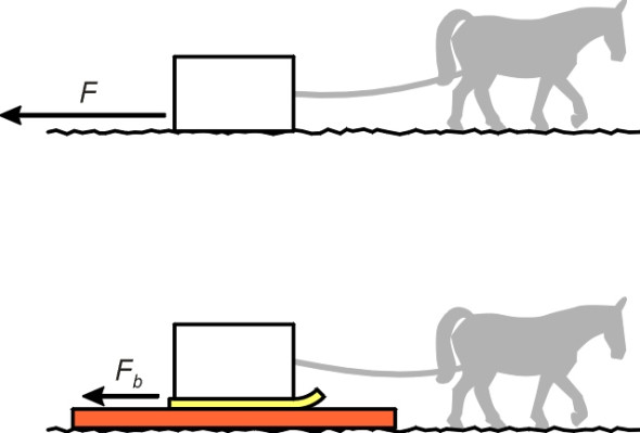
Our carpenter wants to reduce the friction, and with a series of small improvements, he will transform the container into a cart with two wheels. The first step is to tie runners to the container so it becomes a sled, and instead of pulling the sled over the ground, the horse will pull it over a smooth board placed on the ground underneath the runners as shown in figure 1. We now have wood sliding over wood. The coefficient of friction is reduced to a new value \(\mu_b\), and the friction force to \(F_b\), where
(2)
\[\begin{equation} F_b \quad = \quad \mu_{b} Mg \end{equation}\]Things are now easier for the horse, but the sled will soon run off the end of the board. To make progress, our carpenter must put a second board down in front of the sled when it reaches the end of the first, and to keep doing this every few metres throughout the journey.
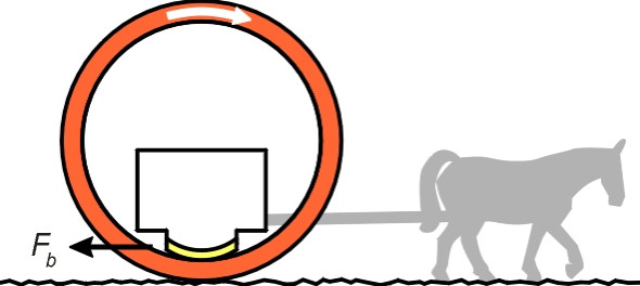
Instead, he (or she) decides on a second step: to curve the board over the top of the sled and make it into a cylinder (figure 2). The running surface now forms a continuous loop. It’s easier to haul the sled if the cylinder is split into two separate hoops, one on either side of the load, and spaced far enough apart for the driver and passengers to see where they are going. The runners can be mounted on outriggers, and the underside of each runner shaped to match the inside surface of the hoop on which it is sliding.
Figure 2
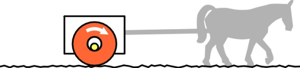
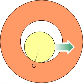
The third and last step is to reduce the size of the aperture in each hoop to a few centimetres across, and replace the runners with stub axles rigidly attached to the container body (figure 3). The sled has now become a two-wheeled cart, and the evolutionary process is complete. The two hoops have been transformed into wheels, and just as important, the smooth surfaces on which the axle rests become sleeve bearings or ‘journals’ that are small enough to be bored out with an auger, and much easier to lubricate. Remember that the engineer has only reduced the diameter of the bore, not the overall diameter of the wheel. The wheel can be as large as one likes, in fact the larger the better, as we shall now see.
Figure 3
The wheel as a lever
People know instinctively that a large wheel makes life easier for the horse, but how much easier? We start with a simplified picture as shown in figure 4. From now on, we’ll treat the two wheels as a single wheel (it simplifies the argument without affecting the logic). The axle is assumed to have a circular cross-section, as is the hole drilled through the wheel. To make things clearer, the axle is shown considerably smaller than the hole, whereas in reality it would fit snugly inside. Viewed in cross-section through the plane of the wheel, there is only a single point of contact between the axle and sleeve bearing surface, and this point of contact lies at C, vertically underneath the wheel centreline.
Figure 4
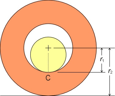
Figure 5
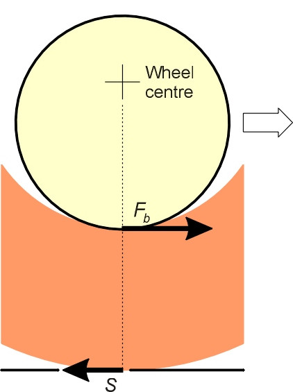
What are the horizontal forces acting on the wheel? We might imagine that as shown in figure 5, the total friction force applied by the axle to the wheels is the same as the original friction between the runners and the board, namely \(F_b\). This friction acts with lever arm \(r_1\)about the centre of the wheel, and opposes its rotation. If the wheel turns at constant speed, there must be a horizontal reaction at the ground, a shear force \(S\) that applies a moment of equal magnitude in the opposite direction, so that
(3)
\[\begin{equation} S \; \times \; r_2 \quad = \quad F_b \; \times \; r_1 \end{equation}\]The force \(S\) represents the retarding force acting on the cart as a whole. From equation 3, it follows that
(4)
\[\begin{equation} S \quad = \quad \left( \frac{r_1}{r_2} \right) F_b \end{equation}\]so we have effectively reduced the resistance by a factor \(r_{1}/r_{2}\). The friction is unchanged because the load is still sliding over a wooden surface, but the geometry has changed and the horse is using the wheel as a lever. The larger the wheel diameter in relation to the diameter of the bearing, the smaller the friction and the smaller the effort needed to haul the cart.
A flaw in the argument
Unfortunately, there is a flaw in the argument. We have made sure that the moments acting about the centre of the wheel balance out, but the horizontal forces do not: \(S\) and \(F_b\) are different. We need to re-draw figure 5 so that both conditions hold.
Figure 6
In fact, the point of contact C between the axle and wheel bearing surface moves as soon as the horse starts to pull the load, as shown in figure 6. We can see this by examining all of the forces that act on the wheel together. At the ground surface, there is a horizontal resistance \(S\) and a vertical reaction \(Mg\) to the cart’s weight. Their resultant is inclined upwards and to the rear as shown in figure 7. It follows that C lies behind the wheel centreline, because at the point of contact within the bearing, there is a normal contact force \(N\) and a friction force \(\mu_{b}N\) whose resultant is inclined downward and to the right. The two resultants must be equal and opposite, which is why they are both labelled \(R\) in the diagram.
Figure 7
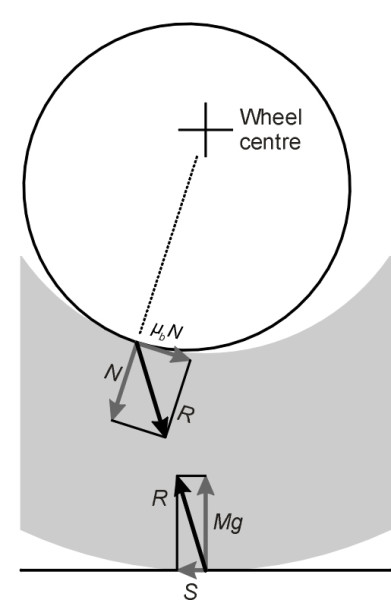
It appears from the diagram that the normal contact force \(N\) inside the bearing is less than \(Mg\), and the resistance \(S\) at the ground less than the friction \(\mu_{b}N\) at the bearing. So we have indeed reduced the resistance to motion, but it is not immediately clear by how much. By Pythagoras’ theorem, the resultant at the contact point C within the bearing satisfies the equation
(5)
\[\begin{equation} R^2 \quad = \quad N^2 \; + \; {\mu_b}^{2}N^2 \end{equation}\]and similarly at the point of contact of the wheel with the ground
(6)
\[\begin{equation} R^2 \quad = \quad S^2 \; + \; M^{2}g^2 \end{equation}\]It follows that
(7)
\[\begin{equation} N^2 \; + \; {\mu_b}^2 N^2 \quad = \quad S^2 \; + \; M^{2}g^2 \end{equation}\]Taking moments about the wheel centreline (positive anticlockwise), we get
(8)
\[\begin{equation} \mu_{b} N r_1 \; - \; S r_2 \quad = \quad 0 \end{equation}\]From this last equation we can derive an expression for \(N\). Briefly, if we substitute this expression for \(N\) in equation 7 and at the same time replace \(\mu_{b}Mg\) with \(F_b\), we can show that
(9)
\[\begin{equation} \frac{S}{F_b} \quad = \quad \frac{\rho }{\sqrt {1 \; + \; {\mu_b}^2 (1 - {\rho}^2)}} \end{equation}\]where \(\rho = r_1/r_2\). For all plausible values of \(\rho\) and \(\mu_b\), the ratio \(S/F_b\) is a few percent less than the value of \(\rho\), which means that indeed, the friction has been reduced by a factor approximately equal to \(r_1/r_2\) as we originally supposed, but not exactly so.
Notice that the point of contact C has moved rearward relative to the direction of motion. Since it is the axle that is pushing the wheel along and not the other way round, this is the opposite of what you might expect. In fact, when the cart starts to move, the contact point rolls clockwise around the inside of the bearing until the static friction is overcome and the two surfaces begin to slide over one another. There is another curious consequence. For a brief moment, the wheel moves faster than the horse.
How the wheel works
The wheels of many of the vehicles built during the 19th century were larger than would be considered normal today. For example, the horse-drawn wagon and the ‘penny-farthing’ bicycle had wheels over 1.5 m in diameter. Even early aircraft had large wheels. We have already seen one reason for this: instead of dragging the wagon across the ground, a horse drags the axle stubs (which carry the load) across the smooth inner surface of the wheel bearings. There is still friction, but the wheel acts as a lever, so the friction is further reduced according to the ratio of the diameter of the bearing to the diameter of the wheel rim.
The benefits of large wheels
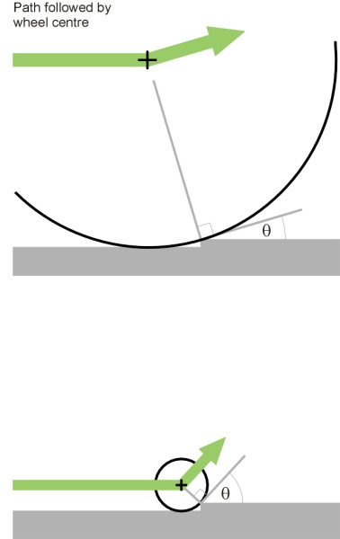
But wheels are not just devices for reducing friction. A large wheel enhances comfort for the vehicle passengers because it effectively smoothes out a rough track surface. This smoothing action is also relevant to energy losses; the geometry is explained in Section G0119 and we’ll only touch on the principle here. Imagine a level track in which there is a small upward step. When the wheel first makes contact with the step, it is jolted upwards (figure 8) because its direction of motion undergoes a discontinuous change. If the wheel diameter is small, the angular change in direction will be severe. However, a large wheel will be deflected at a relatively shallow angle, implying a smaller impulse transmitted to the vehicle and its cargo. On any surface, a large wheel gives a smooth ride.
Figure 8
A large wheel has two further advantages. For a pneumatic tyre of any given tread width, a large diameter allows a larger contact patch, which improves grip. And because it revolves less quickly than a small one for any given vehicle speed, a large wheel reduces wear and tear both on the bearing and on the tyre or rim.
Conflicting requirements
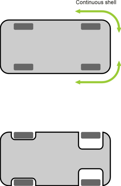
So we shouldn’t be surprised at the unwieldy appearance (by today’s standards) of the wheels mounted on early wagons, velocipedes, and aircraft: large wheels allowed them to move faster. Nevertheless, they were a nuisance, and they continue to be a nuisance because large wheels are heavy and they take up space. The chassis of a truck must be squeezed between the twin rear wheels, with its load-carrying platform raised high above the ground – not an ideal position (figure 9). The front wheels of a passenger car need room to swivel. They constrain the width of the engine compartment and compete with space behind the bulkhead for the passenger footwell. As if that were not enough, they interrupt the continuity of the body structure. Ideally, the body shell would form a continuous envelope around the front of the car, but the front corners have to be cantilevered out from the core structure ahead of the wheel cavities, which makes them comparatively weak at floor level (figure 10). Finally, a heavy car wheel impedes the action of the suspension insofar as it increases the unsprung weight (Section G1115).
Figure 9
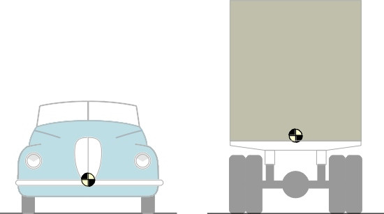
Figure 10
So the modern wheel is a compromise, made possible by relatively smooth roads and aircraft runways, together with pneumatic tyres and more sophisticated forms of suspension. Even so, larger wheels are still needed for buses and heavy trucks, whose tyres have to work extremely hard.
Pointing in the right direction
Dragging a load across the ground is not only hard work, it is hard to control. A sliding contact has no sense of direction, and if the ground surface slopes from side to side, the load is likely to slither off course. This brings us to the final characteristic that makes wheels so useful: they control the direction in which the vehicle moves. Control takes place through the contact patch - the area of contact between the tyre and the ground. Through this critical area are transmitted braking forces that slow the vehicle down (and for a horseless carriage, tractive forces that speed it up). The contact patch also handles the centripetal forces that guide the wheel round each curve in the road.
But it doesn’t follow quite the path you’d expect. Certainly, tyres are designed to roll longitudinally, i.e., in the direction they are pointing. If you release the handbrake of a stationary saloon, you can push it forwards or backwards, but not sideways, as if the tyres were on rails. However, at speeds above about 20 km/h (12 mph), a tyre will drift at an angle to its direction of motion (see Section C1717).
Are there any alternatives?
From time to time, variations on the simple wheel have been proposed, including the ‘hubless’ wheel (essentially a wheel rim that is fed through a roller guide), together with several patent devices with smaller wheels built into the rim so they can move sideways as well. Nor is the wheel the only way of supporting a vehicle. Mechanical legs are a possibility, and in some ways, an air cushion is an attractive alternative, but without the directional guidance provided by contact patches, an air cushion vehicle is not easy to control. Magnetic levitation is equally attractive, but it too needs a track, and it’s very expensive. Throughout, this web site, therefore, we concentrate on the wheel as we know it, and try to draw out aspects of its behaviour that are interesting, and sometimes overlooked.
However, the scope for improvement is not yet exhausted. In the case of railway wheels, what goes on within the contact area where the rim grinds over the rail surface is still not perfectly understood. The same applies to pneumatic tyres (see Section C2019). In fact tyre companies are working to develop varieties that wear less quickly, provide better grip, and above all, draw less energy from the power unit by offering less resistance to motion.
Revised 11 February 2015