C.2009
Dynamic load transfer
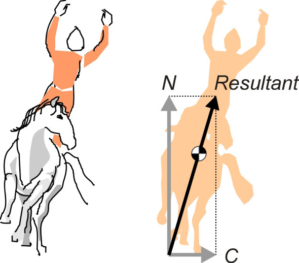
Have you ever watched horses perform at a circus? They canter steadily round the ring, leaning towards the centre (figure 1). We know instinctively they must lean inwards, though we may not be able to explain exactly why. The reason is that a horse needs a centripetal force to keep it on a curved path. Like the stone in a sling, if there were nothing pulling it towards the centre of the ring it would fly off in a straight line. The force is supplied by friction acting laterally on each of its hooves. Unfortunately, its hooves are in the wrong place. If you want to move a horse sideways (or in any direction, for that matter) the best place to push is higher up, at its centre of mass. So the horse re-arranges its geometry, using the upward thrust N on its hooves to balance the centripetal thrust C so it doesn’t fall over. As shown in figure 1, the two forces combine to create a resultant force, and the horse leans until the resultant passes through its centre of mass.
Figure 1
What happens when equilibrium is disturbed
You’ll have noticed that figure 1 only shows the forces acting on the horse’s feet. No mention is made of the centrifugal force that is usually associated with objects moving on a curved path: the force that we feel tugging us outwards when we step onto a moving merry-go-round. This is quite deliberate. Centrifugal force is a slippery concept that we can avoid for the time being by looking at the problem from a particular point of view, concentrating on the external forces and ignoring the internal ones.
The clingfilm criterion
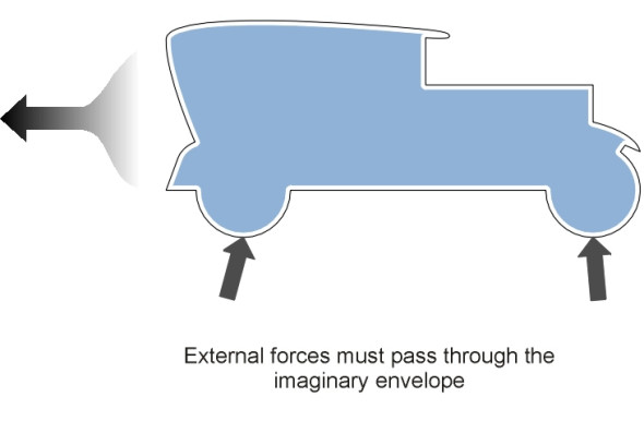
How can you tell whether a force is ‘external’ or not? Let’s think about a motor car for a moment. Notionally, we can cover it with clingfilm (figure 2). In principle, the clingfilm could be made from a photoelastic material that changes colour when squeezed or pulled apart. The coverage must be complete, so that every part of the car including the tyres is sealed off from the outside world. We can now distinguish an internal force by virtue of the fact that it operates entirely inside the envelope, and is not detectable (at least, not directly) from any distortion of the film. Internal forces include the car’s weight together with the so-called inertia forces of which the centrifugal force is one example. But these are embedded entirely within the object’s mass. By contrast, any external force must be transmitted through the film. Whenever the car is influenced by an external force, the film will reveal its presence, showing up for example any aerodynamic disturbance together with contact forces between the tyres and the road.
Figure 2
When describing the circus horse earlier, we ignored what was going on inside the skin of the horse and the skin of the rider and instead looked at the arrangement of external forces in relation to the horse’s centre of mass. By definition, the centre of mass is the point at which the horse’s weight - together with any inertia forces that might influence its motion – act as though it was located. Hence if we take moments about the centre of mass, these forces don’t appear in the equation.
Abolishing inertia?
Nevertheless, inertia forces often appear in textbooks, where they are used to explain the dynamics of moving vehicles. For example, when a cyclist brakes, it is the inertia associated with the rider’s body mass (so the explanation goes) that carries the rider over the handlebars. Centrifugal force is just another variety of inertia force, distinguished by acting sideways rather than fore-and-aft. It can be used to explain why a double-decker bus will tip over if driven too fast round a bend.
The reason we avoided inertial forces when describing the circus horse is that they don’t actually exist. It’s easy to forget that when a horse or a vehicle travels round a curve, it is not in equilibrium and the forces acting on it don’t balance. The centripetal force that keeps the horse’s hooves inside the ring is pushing as it were against an open door. Likewise when a cyclist brakes, the horizontal forces acting on the bicycle wheels are directed rearwards not forwards, and there is nothing to cancel them out. The rider is not pulled over the handlebars: it is the wheels that are dragged back underneath the rider and not the other way round. We have an ‘accelerating system’.
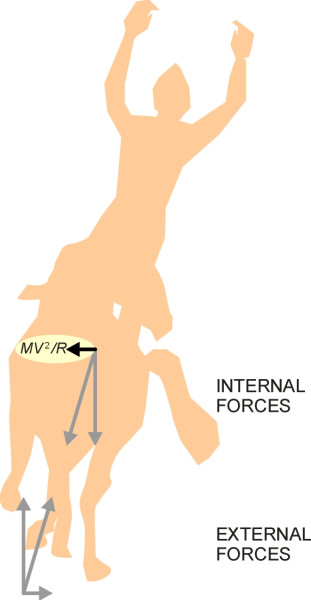
But the inertia force can’t be abolished as easily as that. The French mathematician and philosopher Jean-Baptiste le Rond d’Alembert (1717-1783) showed that an accelerating system could be transformed into an equivalent static system by adding a suitable inertia force. The system could then be treated as if it were in static equilibrium, with all the forces cancelling each other out. The inertia force required to account for any particular acceleration must act in the opposite direction to the acceleration with a value equal to the numerical value of the acceleration times the mass. It is called the d’Alembert force. In the case of a horse and rider of mass \(M\) travelling at constant speed \(V\) round a curve of radius \(R\), the lateral acceleration is \(V^{2}/R\) acting towards the centre of the curve. It can be replaced by an equivalent d’Alembert force of value \(MV^{2}/R\) acting laterally towards the outside of the curve, and this is what we normally describe as ‘centrifugal force’. If nothing else, the d’Alembert force can help by reducing static forces and dynamic accelerations into the same units so they can be plotted together on a force diagram (figure 3). It balances the accounts and provides a check on whether we have missed anything out. We will use it elsewhere when dealing with more complicated phenomena such as vehicle body roll.
Figure 3
For the time being, however, we will continue to relate the external forces to the centre of mass. Our main interest lies in the normal contact forces that act on car tyres. As we saw earlier, the total of the normal contact forces remains fixed and equal to the weight of the vehicle provided it is travelling on a level road. But when we look at individual wheels, the situation changes. The normal contact force on an individual tyre varies from moment to moment during each journey.
Load transfer
On a real road, variations in wheel load occur when the suspension rides over bumps and hollows in the carriageway surface. But there is another kind of variation that occurs even on a perfectly smooth, level surface, purely because of the way the car is being driven. Variations of this kind are sometimes described as ‘weight transfer’, but ‘load transfer’ is perhaps a better description. When a vehicle moves, the distribution of weight among the wheels doesn’t change because gravity continues to act in the same way regardless of what the driver does. The reactions arising from the vehicle’s weight will therefore remain constant. But superimposed on these reactions are loads that arise as a consequence of braking, acceleration and cornering. Individually, they can be either positive or negative, but their total must be zero. We therefore speak of load transfers among the wheels. The transfer can take place between the front and rear axles, or from one side of the vehicle to the other, or a mixture of the two.
Longitudinal transfer
Suppose the wheelbase of the car is \(L\) and its centre of mass lies a distance \(h\) above the road surface (figure 4). When the driver brakes, a horizontal force is applied to the wheels at road surface level. As with the horse’s hooves, the wheels are too low down to deliver the force where it’s needed. Braking will not only slow the car down, but also exert a couple about the car’s centre of mass. The couple acts in such a way as to tumble the car over on its nose, like a cyclist being pitched over the handlebars.
Figure 4
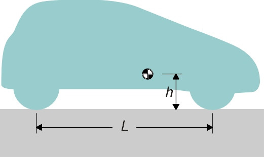
Figure 5
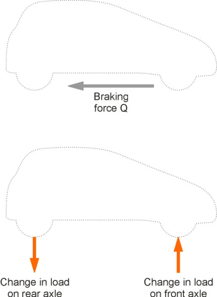
Referring to figure 5, if the total horizontal braking force acting through the contact patches is \(Q\), the couple produced by the braking force about the centre of mass is \(Qh\) clockwise. If we call the increase in normal contact force at the front axle \(\delta P\), with the corresponding change at the rear axle \(- \delta P\), then the resisting couple is \(\delta P L\). Hence \(Q h - \delta P L = 0\) and we observe that the increase in load at the front wheels is given by
(1)
\[\begin{equation} \delta P \quad = \quad Qh/L \end{equation}\]In fact, without some careful engineering of the suspension, the car will ‘dive’ or pitch nose-down to some degree. No ordinary car will tumble over, because the front and rear axles are sufficiently far apart for the couple to be balanced by a change in the vertical reaction forces of the wheels with the ground.
An opposite effect occurs during acceleration, when the load shifts towards the rear axle and the vehicle tends to ‘squat’ tail-down. In this respect, the car designer faces an interesting problem. For a rear-wheel drive car, a rearward load transfer during acceleration improves grip at the driven axle so the driver can make better use of the engine power without spinning the wheels. But for a front-wheel drive car the load transfer is a nuisance: no matter how powerful the engine, when you accelerate, some of the load shifts to the rear axle and grip is reduced at the driven front wheels. You can observe the effect if you stand near to a T-junction in wet weather. When a front-wheel drive car emerges from the side road, you will often hear the tyres slip and shudder as the driver tries to accelerate quickly into a gap in the traffic.
Figure 6
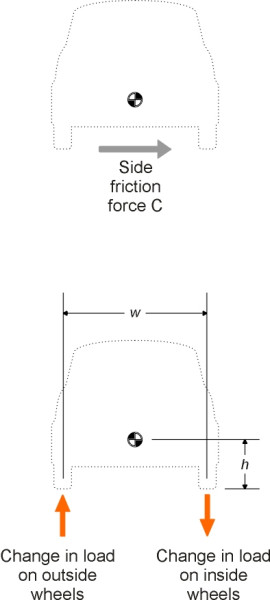
Lateral transfer
When a car travels round a curve, load is transferred from the inside wheels to those on the outside of the curve (figure 6). If we denote by \(C\) the centripetal force required to hold the car in its curved path, and by \(w\) the track width (the lateral distance between the wheels), then the total increase in load \(\delta P\)carried by the outside wheels is given by
(2)
\[\begin{equation} \delta P \quad = \quad Ch/w \end{equation}\]There is a corresponding reduction in load on the inside wheels, and in an extreme case if the load falls to zero, the inside wheels will lift off the road surface and the car will roll over. We’ll come back to this possibility later, in section C1508.
Some practical implications
Designers like to keep load transfer as small as possible, so that all four tyres are pressing equally on the road or nearly so, because the grip provided by a tyre does not increase or decrease in proportion with the normal contact force (see Section C1717); the gains and losses don’t balance out. This applies equally to braking and cornering manoeuvres. But in the case of braking, there is an additional complication.
Under emergency braking, the load distribution between front and rear axles on a typical car changes very roughly from 60:40 to 80:20 [1] [2]. The normal contact force at the rear is greatly reduced, and the maximum frictional resistance that it can contribute is reduced accordingly. So if the same braking torque is applied to the front and rear wheels, the lightly loaded rear wheels will lock up and as a result, lose some of their braking force. Worse, the car will become directionally unstable, slewing round to face in the opposite direction (see Section C0415). To prevent this, the engineer must interpose between the driver’s brake pedal and the four brake disks a system for balancing the distribution of braking effort in proportion to the instantaneous wheel loads, which requires some fairly sophisticated engineering (Section C0816).
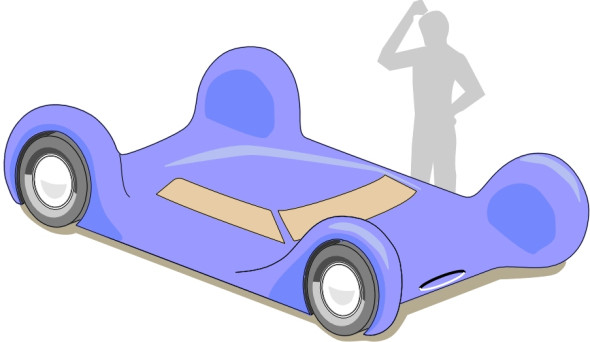
Whether or not the braking forces are managed in this way, it is still a good idea to configure a vehicle so that load transfer is always minimised. The solution is to make \(h\) as small as possible and \(b\) as large as possible. Similarly, to maximise cornering grip, one makes \(h\) as small as possible and \(w\) as large as possible. Briefly, the car should be long, low and wide, with a wheel at each corner (figure 7). If you buy a supercar, you’ll need a bigger garage.
Figure 7
Revised 16 February 2015