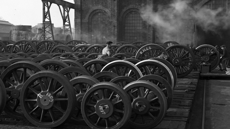
© Barry Duffield Photography
R.1610
The wheelset
Unlike those of a road-going automobile, the wheels of a railway vehicle are built to a simple pattern that has changed little in the last hundred years. Heavy and robust, they are intended to survive large impacts. Reliability is important not least because of the numbers involved: there may be approaching 100 wheels on a high-speed passenger express train and any failure could do a great deal of damage. Our aim in this section is to explain in simple terms how wheels are constructed and how they guide themselves along the rails.
The railway wheel
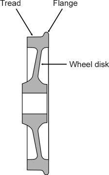
A typical railway wheel carries a load of about ten tonnes, roughly twice the equivalent for a road-going truck. The outer surface is called the tread. With a diameter typically of 1.0 m or less, the tread is roughly 100 mm wide. Like a pneumatic tyre, the railway wheel must handle the various forces needed to propel the vehicle forwards, slow it down, and hold it centrally on the track. But there are three striking differences. First, each railway wheel has a narrow lip or flange on the inside edge whose purpose is to stop the wheel from slipping off the rail (figure 1). Second, the contact stresses between the wheel and the running surface are much more concentrated than those associated with a pneumatic tyre, reaching values that, paradoxically, exceed the yield point of the steel from which they are made. Third, railway wheels are almost always coupled together in pairs, each pair joined by a rigid axle to form what is known as a wheelset. A wheelset is extremely heavy by comparison with its equivalent on a road-going vehicle, and when you look at the various components, it’s not difficult to see why. Let’s start with the disk.
Figure 1
The wheel disk
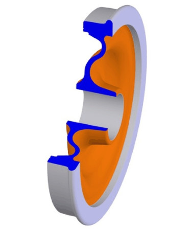
One can think of a railway wheel as a solid disk whose tread is machined into the desired profile. In practice, some wheels have a separate ‘tyre’. The tyre, usually about 60 mm thick when new, is made of hardened steel. It is heated and pressed onto the wheel disk, where it shrinks as it cools and tightens its grip so that no bolts are needed to hold it in place. Ideally, for a smooth ride the diameter of the wheel should be as large as possible (see Section G1209), and in fact, the driving wheels on some early steam locomotives were 9 feet (over 2.7 metres) in diameter. They were magnificent examples of craftsmanship, and they needed to be large because they were driven by connecting rods, pistons and valve gear that were liable to fail if worked too fast, and a large wheel compensated by carrying the loco further along the track for each piston stroke. Later, when these limitations were overcome, the driving wheels were scaled down to a more manageable size. Nowadays, they are made of pressed steel, and for many the cross-section is wavy rather than flat (figure 2). A wavy cross-section provides resilience and allows the rim to expand and contract slightly with changes in temperature without putting the disk under too much stress; useful properties for tread-braked wheels and those with separate tyres. Rubber inserts make the wheel more resilient still, helping to reduce any impact on the suspension when it passes over a gap in the rail.
Figure 2
The axle
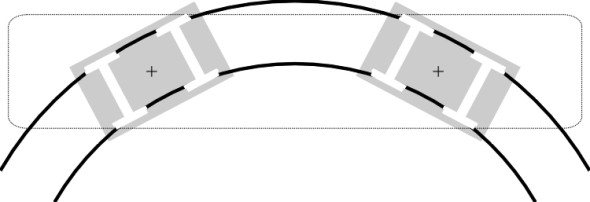
The axle of a wheelset performs several tasks. First, it carries the weight of the vehicle. The weight is conveyed to the axle via an indirect route: on most rail vehicles the axles are grouped in pairs, each pair being mounted on a bogie that swivels so it can follow curves in the track (figure 3). As will be shown in Section R0505, the bogie frame surrounds the wheels so that the outer end of each axle can fit into a bearing that is housed in an axle-box mounted on the bogie frame (it’s possible to locate the frame inboard of the wheels but this is unusual). Hence the weight of the vehicle carried by any particular wheel is conveyed first through the bogie and then the bearing to the end of the axle and thence through the wheel disk to the rail below.
Figure 3
The second task is to transmit torque. A powered axle is usually provided with a toothed gearwheel or pinion mounted somewhere near the centre that receives power from an electric motor. The axle transmits torque from the pinion outwards to the wheels. Axles that are not powered are called trailing axles: a trailing axle is intended to roll along freely, but on a modern vehicle it still has work to do because it is fitted with one or more brake disks that likewise apply torque that must be carried out to the wheels.
Finally, the axle provides a rigid connection between the left and right wheels so they are always rotating at the same speed. This is the dominant feature of a conventional wheelset that causes it to ‘steer’ along the track without the flanges grinding against the inner faces of the rails. For all these reasons a railway axle must be torsionally stiff and strong, with the wheels firmly fixed at either end. Trailing wheels are normally wedged into place either by press or shrink fit [24] while driving wheels need a ‘key’ to stop them working loose. Drawings of various configurations can found in [6] and in [18]. The axle is usually solid steel and since its diameter normally lies within the range 150 to 200 mm, the complete wheelset can weigh as much as a small car [22].
Bearings
In the days of steam, locomotives needed a continuous supply of oil to the axle-boxes and various other bearings to keep the vehicle moving. As Dr Tuplin reminded us in his book [29], a large loco could have 60 separate oil reservoirs, one attached to the top of each bearing. The reservoirs might take an hour to check and fill up before each day’s work. The axle bearings were made of bronze with white metal linings, white metal being an alloy of tin. Bearings were commonly grooved in the mistaken belief that the grooves encouraged oil to spread itself uniformly over the bearing surface. As a result, the axle-boxes consumed nearly 1.5 litres of oil per bearing for every 1000 km travelled. Failures were common. Excessive wear or an absence of lubricating oil would quickly cause the bearing to overheat and give off smoke. If the problem wasn’t detected, the bearing would disintegrate, which is why railway workers considered the axle bearings as the most vulnerable parts of a moving vehicle. Modern trains are not immune because they travel further and faster than their steam-hauled predecessors. In the UK, the programme for introducing high speed trains was halted when an axle box fractured on a Mk III passenger coach. The coaches were taken out of service until, after intensive research and development, they reappeared with a strengthened design [15].
Roller bearings have replaced plain bearings on many vehicles (see Section G1615), and although they don’t need regular lubrication, they are more expensive and don’t necessarily give any warning before they fail [4]. And the simplest kind with cylindrical rollers can carry only ‘radial’ loads that act at right-angles to the wheelset axis, these being in the railway context (a) the vertical weight of the vehicle and (b) the longitudinal ‘push’ and ‘pull’ forces associated with traction and braking. In practice, a railway wheelset must also convey lateral forces such as the centripetal force that guides the vehicle body round each curve in the track, together with any sideways impacts arising from irregularities in the track alignment. Some railway vehicles have conical bearings that can transmit lateral as well as vertical loads, although they are relatively expensive and generate more heat. On high speed trains, the problem is often handled in another way. Within each axle-box there may be three separate sets of bearings, two sets having cylindrical rollers that transmit radial forces, with a ball-bearing sandwiched between them to carry axial loads [21].
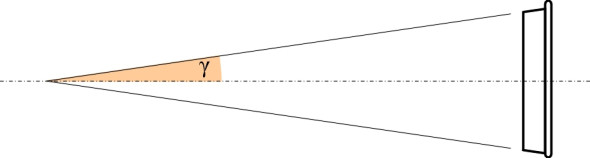
The conical tread profile
The distinctive profile of a railway wheel with a flange on the inner face is not exactly new; it dates back at least to the seventeenth century when flanged wheels made of wood were used in the mining industry, guiding the trucks that carried coal and metal ores away from the pit-face. While modern rail wheels appear to have a similar shape, the flange is much smaller, projecting only 30 mm from the tread, and the geometry has evolved so that for most of the time, the flange doesn’t actually touch the rail. Instead, the wheel is guided by the tread alone, which has a shallow taper not obvious the naked eye. In many countries, the taper is standardised at 1:40, so that the tread surface forms part of a long, narrow cone (figure 4). The conicity of a wheel tread is defined as the tangent of the half-angle \(\gamma\) subtended at the apex of the cone (figure 5). Since \(\gamma\) is small, to a close approximation the tangent is equal to the angle itself expressed in radians. The cone-shaped tread means that the effective radius of a railway wheel is not fixed, but depends on the lateral position of the wheelset relative to the track centreline. This feature, combined with the solid axle, gives the vehicle an almost magical ability to steer itself around curves in the track.
Figure 4
Figure 5
Behaviour of the wheelset
When a vehicle follows a curved path, the wheels on the outside of the curve must travel further than the wheels on the inside. This true for rail vehicles and road vehicles alike. Hence the rear axle of an automobile must allow the wheels at either end to rotate at different speeds otherwise one of them would scrub along the road surface and put the whole chassis under strain. This is not a problem for railway vehicles because of the tapered profile of the wheels. Although they are constrained to revolve at the same rate, the axle can move sideways a few millimetres relative to the track centreline so that the outer wheel covers a slightly longer distance for each revolution than the inside wheel. This is the principle that underlies the self-steering properties of a railway wheelset.
The steering wheelset
The geometry is straightforward. Imagine the wheelset centrally located on the track such that the rolling radius of the left hand wheel and the rolling radius of the right hand wheel are both equal to \(r\), say. When the wheelset deviates to the left by a small distance \(y\), the left-hand wheel - let’s call it the ‘outer’ wheel - rides up on the rail, and the radius \(r_{outer}\) of that part of the tread in contact with the rail increases by \(\gamma y\) thus:
(1)
\[\begin{equation} r_{outer} \quad = \quad r \; + \; \gamma y \end{equation}\]Similarly, the rolling radius of the right-hand wheel - let’s call it the ‘inner wheel’ - decreases by \(\gamma y\), so that
(2)
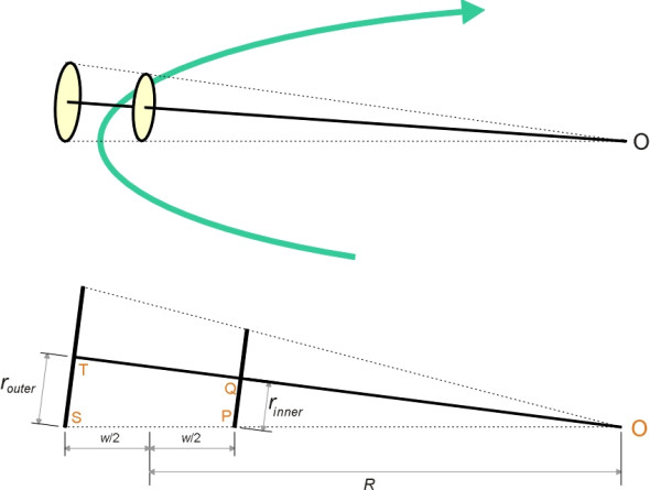
\[\begin{equation} r_{inner} \quad = \quad r \; - \; \gamma y \end{equation}\]So if the wheelset deviates to one side, the outer wheel travels further during each revolution, which forces the wheelset to yaw back in the opposite direction. In other words, a displaced wheelset automatically compensates by returning towards a central position on the track, and in fact under ideal conditions it will steer round curves without either of the flanges touching the rails at all (figure 6).
Figure 6
We can easily work out the maths if we imagine that whenever the wheelset shifts away from its central position, it behaves like a cone rolling about its apex ‘O’ as shown in figure 7 (this cone shouldn’t be confused with the conical surfaces of the wheel treads). Denote by \(w\) the width between the contact points on the two rails, then by similar triangles OST and OPQ,
Figure 7
(3)
\[\begin{equation} \frac{r_{outer}}{R + \frac{w}{2}} \quad = \quad \frac{r_{inner}}{R - \frac{w}{2}} \end{equation}\]and if we substitute for \(r_{inner}\) and \(r_{outer}\) via equation 1 and equation 2 this becomes
(4)
\[\begin{equation} \frac{r + \gamma y}{R + \frac{w}{2}} \quad = \quad \frac{r - \gamma y}{R - \frac{w}{2}} \end{equation}\]which can be rearranged to give
(5)
\[\begin{equation} R \quad = \quad \frac{rw}{2\gamma y} \end{equation}\]So equation 5 confirms what we might expect: the cone angle affects the path followed by the wheelset. Other things being equal, the larger the cone angle, the sharper the curve a vehicle can negotiate, a fact that George Stephenson discovered early on during the development of steam railways in Britain [8]. And for any given cone angle, the radius is inversely proportional to the lateral shift \(y\). A small shift will produce a shallow curve, while a large shift is needed to steer a sharp curve.
Unfortunately, after it has left the factory a conical wheelset doesn’t remain conical for very long, because in service, the tread is worn to a concave profile (figure 8). This changes the geometry. As we’ll see later in Section R0415, the equivalent conicity is much larger than the nominal value, and hence a railway vehicle with moderately worn wheels will steer round curves of smaller radius than the same vehicle with new wheels. On the other hand, when the wear reaches a critical level, among other things the wheelset becomes more likely to jump the rails (Section R0314). Hence, a wheelset must be re-profiled at frequent intervals, although its life can be prolonged by machining to a curved profile (we’ll return to this and related matters in Section R0415).
Figure 8
Noise
Given that the surface of a rail is smooth compared to that of a motorway for example, people are often surprised to learn that for trains travelling at typical railway speeds (40 km/h up to 300 km/h) the noise that they make comes mainly from contact between the wheels and the rails [14] [26]. Nowadays the interior of a train is likely to be well insulated so passengers don’t notice, but fifty years ago you could hear it when moving through the vestibule from one railway coach to the next, and since the level rises as the cube of speed [10], on an express train between stations it was almost deafening. The explanation lies in the shape of the railway wheel.
You might not recognise the resemblance straight away, but a railway wheel is like a church bell [27]. Both have roughly the same weight and size, and both are made of a resilient material. Moreover, their shapes are closely related, though the railway wheel is flattened into a single plane. Hence their acoustic properties are very similar, which makes the railway wheel an efficient amplifier that rings loudly when struck, transforming the input and broadcasting it to the surrounding landscape. At one time, it was common practice for a workman to check for cracks in the wheels of a train before departure by tapping each one with a hammer: if the wheel was cracked, it failed to produce a clear ringing sound. Not surprisingly, the wheel ‘rings’ unaided when travelling at speed, stimulated by small irregularities in the rail surface impacting on the hard surface of the tread. Short wavelengths cause relatively little trouble because of a mechanism known as the ‘contact filter’ (see Section R1114). The contact patch, which is 10-15 mm long, bridges across small irregularities so they don’t inject pulses into the wheel. Most of the noise and vibration comes from larger irregularities, and measurements have revealed a peak at a wavelength of about 6 cm, corresponding to regular bumps in the rail surface known as corrugations. How they arise is an interesting puzzle that we’ll investigate further in Section R1605.
There is roughness in the wheel tread too. In the case of freight wagons, much of the roughness is created by the cast iron brake blocks that press directly onto the tread surface. Tread-braked wheels develop greater roughness than disk-braked wheels [9], and since freight wagons typically last 50 years, it is nowadays considered a good idea to replace the cast iron shoes with something less likely to damage the wheel surface. Since 1999 the international railway union UIC has pursued the development of blocks made from composite material [28].
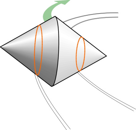
Modes of vibration
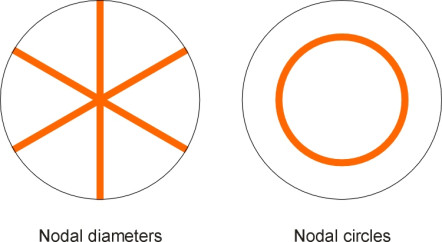
A railway wheel can be likened to a flat disc that is clamped firmly at its centre. As just described, the disk is made to vibrate (‘excited’) by roughness in the wheel and rail surface, which injects an irregular wave form that does not have a single, fixed frequency but many frequencies spread across a wide continuum, although there will often be a concentration of energy around one particular value. So what effect does this produce? The disk vibrates, but its response is not uniform across the range of input frequencies because it has a natural mode of vibration - in fact several natural modes - each with a distinctive resonant frequency. Some modes involve vibrations at right angles to the plane of the disk, some involve pressure waves in a radial direction within the plane of the disk, and some involve circumferential pressure waves around the periphery. The three categories are labelled as axial modes, radial modes and circumferential modes respectively (figure 9). Not only are there three types of resonant mode, but for any given mode, the amplitude varies from place to place within the area of the disk. Some parts vibrate with a high amplitude in phase with each other, while others vibrate \(180^\circ{}\) out of phase. The areas of high amplitude are separated from one another by nodal lines where there is no movement at all. The nodal lines will in some cases divide the disk into radial segments, and in other cases into annuli as shown in figure 10.
Figure 9
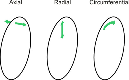
Figure 10
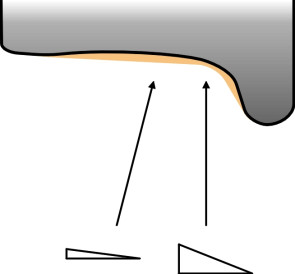
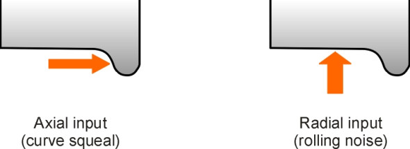
The different modes are excited by different kinds of interaction between the wheel and the rail. When the train goes round a sharp curve, it is the lateral reaction from the outer rail pressing on the wheel flange that generates axial input (figure 11). The wheel vibrates in one or more axial modes and the result is an unpleasant squeal. On the other hand, when the wheel rolls along a straight track the input is provided in a vertical direction from roughness in the track surface, which excites coupled radial and axial modes with one nodal circle, typically at 2 kHz [27].
Figure 11
All of the foregoing is meant to explain how a railway wheel transforms roughness input into a noise output that peaks at certain frequencies depending on the shape and mass of the wheel. However, we have glossed over the fact that because the wheel is rotating, it isn’t possible to detect any nodal lines because the irregular surface of the rail makes for an irregular input that excites different patterns from one moment to the next around different sections of the tyre [25]. An exception occurs when the rail surface is corrugated with bumps at more-or-less equal intervals, a phenomenon we’ll describe later in Section R1605. Corrugations inject a regular pulse into the wheel that can raise the level of noise emissions by 10 dBA, a phenomenon sometimes referred to as ‘roaring rail’ [9].
Noise reduction
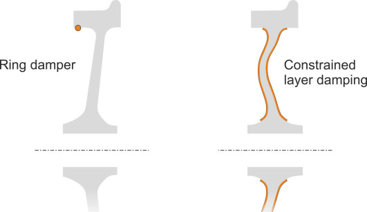
The noise emitted from a railway train can be reduced either by modifying the wheels or by fitting energy-absorbing devices to them. A summary can be found in [28], and we’ll pick out only a three examples here. A device commonly used on urban trams is a resilient wheel made up of three components: an inner disk and an outer steel tyre separated by a rubber or plastic insert that isolates or partially isolates the tyre from the hub. The insert is V-shaped in cross-section and fixed in place by a clamping disc and locking ring; the principle is shown in figure 12. An alternative approach is to fit damping devices to conventional (solid) wheels. Damping devices fall broadly into two classes: (a) those that absorb energy across a continuous range of frequencies, and (b) tuned absorbers. Examples of the first kind are shown in figure 13. The ring damper clips into the wheel rim and rubs against the disk surface when it vibrates, which dissipates some of the energy. The constrained layer damper is a sheet of visco-elastic material that presses against the wheel disk and resists vibrational motion, dissipating the energy internally in the form of heat. It is held in place by a metal sheath. By contrast, a tuned absorber makes use of the phenomenon we noted earlier, that a rigid disk vibrates preferentially in certain modes each having a characteristic resonant frequency, and the device consists of a set of blades each tuned to one of the resonant modes. Several absorbers are needed for each wheel, bolted to the inside of the rim or the outer extremity of the web. If the blades are fixed parallel to the web, the absorber can damp axial modes and hence reduce curve squeal. If the blades are arranged parallel to the running surface they can damp radial modes.
Figure 12
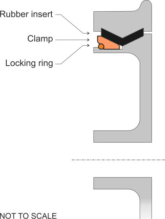
Figure 13
Maintenance
Both the wheel and the rail surface wear over time. But the wheel tread wears more quickly and adopts the shape of the rail rather than the other way round [20]. This is because (a) it is made of softer steel [12]and (b) since the perimeter of the wheel is much smaller than the length of rail over which it runs, each element of the perimeter is subjected to far more impacts than each element of the rail.
Wheel wear
The tyre wears because when it rotates, any small projections on the surface are carried one after the other into the contact patch. Under enormous pressure, they become momentarily bonded with the rail surface, and the tips are torn away on exit. Also, loose particles are caught and trapped briefly between the wheel and rail, where they act like an abrasive and gouge away materal from both surfaces [2] [16]. Deterioration of the wheel is not just a matter of losing tread thickness: more serious forms of damage can occur. A curve in the track may put the running surfaces of all four tyres on a bogie under stress because they ‘fight’ against one another, producing shear stresses on top of any braking or traction forces that arise when the vehicle is speeding up or slowing down. There are two reasons for this. First, the outside wheels must travel further than the inside wheels, and while this is normally accommodated by the steering action of the wheelset which permits a small difference in rolling radius, if the curve is a sharp one the flangeway clearance may be insufficent and the tread surfaces and the outer wheel flange will grind longitudinally against the rail. Secondly, all the wheels are obliged to run at a slight angle to the direction they are pointing so there is an element of lateral grinding as well. Repeated deformation leads to surface cracks which gradually lengthen as they are pulled apart by successive impacts. Material can flake away from the surface [17] and if a crack turns inwards it can lead to a broken tyre. This is just one form of what is more generally termed rolling contact fatigue [5]. There is also the possibility of regularly spaced corrugations on the tread surface similar to those occurring on the rail head (see Section R1605), and quite apart from creating noise, they cause rapidly fluctuating stresses that increase the rate of fatigue damage to the wheel, a phenomenon that was thought to be a factor in the 1998 Eschede rail disaster in which a broken wheel led to the derailment of a German high-speed train together with many casualties [11].
Re-profiling
Ideally, you want the surface of a tyre to spend its whole life in a state of compression. If the particles are squeezed tightly together around the circumference, they are less likely to cleave apart when they collide with the rail, and cracks cannot easily develop. This is why many railway companies use heat treatment to lock in a circumferential stress that protects the wheel from fatigue damage [13]. Nevertheless, with or without heat treatment, the rate of loss of material from the tread is quite fast and a railway wheel must be re-profiled roughly every 100 000 km, possibly every 2 - 3 years of operation [23]. This is an expensive operation. Using manual methods, it can take 8 hours to check the wheel profiles and brake disk wear on a 72-wheel coach set, and the re-profiling work requires heavy lathes and skilled craftsmen, who are careful to ensure that the two wheels making up each wheelset have the same rolling radius so it doesn’t have a built-in bias which would make it veer permanently to one side of the track. All this keeps a vehicle out of service, so there is pressure to streamline the process. Some railway depots now have lathes installed that can re-profile wheels without removing them from the vehicle [3]. Alternatively, wheels may have separate tyres around 70 mm thick. A separate tyre can easily be replaced, an operation usually carried out when it has lost about half of its original thickness.
Conclusion
If maintained in good shape, a railway wheelset will steer itself without any external guidance, keeping (mostly) within a few millimetres of the track centreline. To do this, the wheels must be rigidly connected, with sufficient clearance between the flanges and the rail corners to permit a little sideways movement. When the vehicle enters a curve, the outer wheel rises higher on the rail so it travels slightly faster than the inside wheel, and it’s the difference between the two rolling radii that steers the axle round the curve. But there are occasions when the principle doesn’t work as well as one might wish. Firstly, on an urban tramway many of the curves will be too sharp for the wheels to gain the necessary difference in rolling radius; in fact most tramways don’t have conical wheels at all and the steering is carried out by other means. Secondly, at high speeds the wheelset can become unstable, oscillating from side to side so that the wheel flanges bang alternately against the inside edge of the left-hand and right-hand rail. Nevertheless, most of the problems have been overcome, and in the next few Sections we shall see how the coned wheelset in combination with carefully engineered suspension has enabled railway trains to travel safely at speeds many times faster than a car or truck.
Loose ends
1. Railway vehicles steer themselves because in principle, each pair of wheels is rigidly coupled together so that they rotate at precisely the same speed. But an axle is never quite rigid: steel has a degree of torsional elasticity that in principle allows relative movement. Does this movement affect the capacity for self-steering, and what is the characteristic frequency of torsional oscillation of the axle between the two wheels?
2. The wheels of a railway vehicle undergo a considerable pounding because for every kilometre travelled, each sector of the tread impacts the rail surface about 300 times. You might imagine that to compensate, the engineer would choose a very hard alloy for the tyre surface, harder than the rail. In practice, it’s the other way round. Wheels usually wear more quickly, not just because of the greater number of impacts but also because of the amount of material lost from the rim during each impact. When sand is present as a friction modifier, the rate of loss from the wheel is more than twice the amount lost from the rail surface [12]. Why do engineers choose a softer material? Do they want the wheel to wear more quickly, or is there some other reason?
Acknowledgements
Figure 0: Wheelsets photo kindly provided by Barry Duffield Photography.
Figure 2: Bonatrans wheel model 29, image from company web site http://www.bonatrans.cz/en/bonatrans-stress-optimized-wheels-and-wheelsets.html, accessed 22 January 2013, no longer available.
Revised 05 August 2021