R.1603
Turnouts
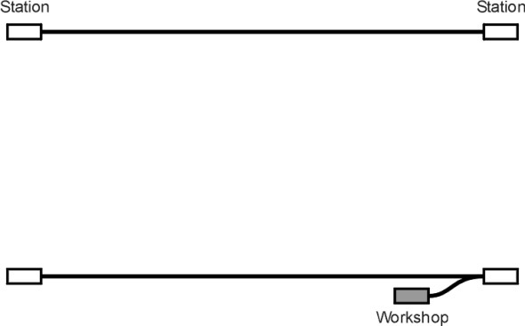
If you wanted to, you could build a railway line without any junctions. It would have a single track and a single train that shuttled backwards and forwards among the stations along the line. But sooner or later the train would need to be taken out of service for maintenance, leaving the line clear for a second train to take over. A spur of some kind would be needed to access the workshop (figure 1). If you wanted to run more than one train simultaneously you’d probably need two tracks, together with some means for switching trains between them, some sidings for loading freight wagons and storing passenger coaches, and in reality, any railway system needs junctions where vehicles can branch to different destinations. So some kind of apparatus for switching between alternative paths is vital. In the USA, the is called a switch or turnout, while in the UK it is called a set of points. We’ll call it a turnout. For safe operation the turnout requires signal control together with safety interlocks to ensure it is working correctly [5] [8]. But in this Section we’ll concentrate on the mechanical operation of the turnout itself together with the track layout.
Figure 1
Layout
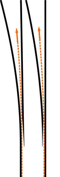
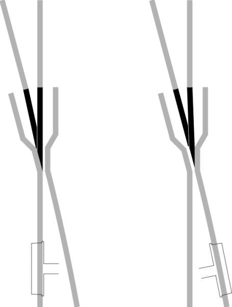
There are several different kinds of turnout and figure 2 shows the simplest kind. You can think of it as a letter ‘Y’ having a main stem with two branches. The layout is usually designated as ‘facing’ or ‘trailing’ (figure 3). This has nothing to do with the turnout as such, but rather the direction of the prevailing traffic flow. At a facing turnout, a train arrives via the stem and is offered either of two exits according to the position of the moving switch-blades. One of the two blades must be locked firmly against the fixed rail, otherwise a wheelset may ‘split the points’ and the train will derail (figure 4). At a trailing turnout, a train arrives via one of the two branches: they converge into one and the train exits along the common path. A trailing turnout is less likely to cause a derailment because even if the switch-blades are not correctly set, the momentum of the train tends to force them into position.
Figure 2
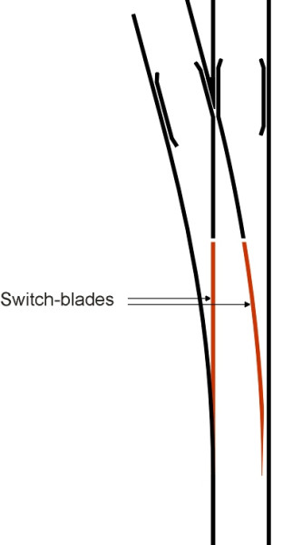
Figure 3
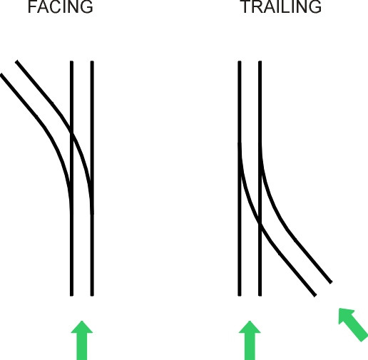
Figure 4
Geometry
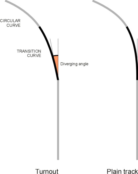
Turnouts are commonly used to provide access to a branch line from a main line. The main line usually follows a straight path through the junction that allows express trains to pass through at speed. Let’s imagine it’s a facing turnout, so the approaching train is given the choice of staying on the main line or diverging away from it. The diverging route follows a transition curve whose radius of curvature R at the exit determines the frog angle\(\;\)(figure 5) and indeed the length of the whole assembly. In principle one could work out the geometry of the transition curve using a clothoid or a cubic parabola in the same way that one could fit a transition curve between a straight and a circular curve on plain track, but in practice things are more complicated (figure 6). On plain track, the transition curve is tangential to the straight so the alignment flows smoothly into the curve, but this cannot be the case for a turnout because it would make the whole assembly too cumbersome and also create difficulties at the toe of the switch-blade, which would be rather flimsy. So in a turnout the alignment starts at a finite angle, which causes a distinct jolt on the suspension whenever a vehicle follows the diverging path. Moreover, there can be no superelevation. Hence the speed at which a vehicle can move through the turnout is less on the diverging exit than it is on the main exit. To maximise the speed and minimise discomfort, the curvature of the switch-blade is nowadays optimised using computer simulation that takes into account dynamic loading.
A modern turnout is prefabricated and carried to the site for installation in built-up sections or even as a single unit. Some units are larger than others. Until recently, turnouts were designed for an exit speed on the diverging route of around 60 km/h, which could safely be accommodated with a curve radius of 500m together with a frog angle of around 1:12 [6]. With an overall length of 25 m, the unit was reasonably compact, and relatively straightforward to make and install. But the geometry has changed for modern high-speed railways. For example, in Germany, high-speed turnouts with a frog angle of 1:42 are designed to operate at vehicle speeds on the diverging branch of 200 km/h [7]. In some cases, the overall assembly is nearly 200 m long.
Figure 5
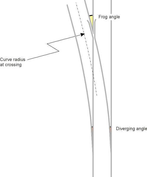
Figure 6
Junction layout
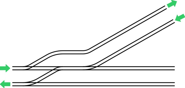
Turnouts are often installed in pairs. For example, a mainline railway will usually have two tracks, one for each direction of movement, and the tracks will be connected by two opposing turnouts to form a crossover that trains can used to switch from one track to the other (figure 7). A more complicated situation arises at a junction between a twin-track main line and a twin-track branch line. Not just one but three separate assemblies are needed: two turnouts and a diamond crossing (figure 8). A conventional diamond has gaps in the rails where alternative wheelpaths intersect (figure 9), eight in all compared with two in a simple turnout. As we’ll explain shortly, the gaps produce sizeable impacts on a vehicle suspension that tend to wear out the wheels, the suspension, and the rails themselves, and the four sub-assemblies where the crossing gaps occur are among the most expensive components of a railway track, needing frequent maintenance and renewal. During the 1980s, there was a systematic programme aimed at simplifying the track layout at railway stations in the UK, and many diamond crossings were eliminated by converting the junction layout to a single-lead junction [3]. A single-lead junction (shown diagrammatically in figure 10) requires the diverging route to be reduced to a single track initially with a crossover upstream, which involves trains running temporarily in the ‘wrong’ direction on one of the mainline tracks. However this arrangement contributed to several accidents, notably in 1989 at the Bellgrove junction near Strathclyde, when two trains collided head-on [9]. In a proposed alternative arrangement shown in figure 11, the single lead is replaced by two leads, one of which combines a crossover with a second diverging point.
Figure 7
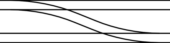
Figure 8
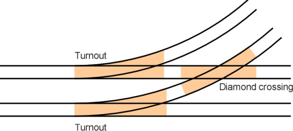
Figure 9
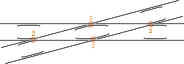
Figure 10
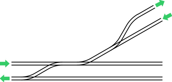
Figure 11
How a turnout works
The principle underlying a railway turnout is two hundred years old and to modern eyes, perhaps, ungainly. The aim is to force the wheels to follow one of two prescribed paths, by moving the switch-blades bodily from side to side. The blades rest on greased supporting chairs and are not anchored to the track assembly over a considerable length between the toe and the heel, where they are clamped to a sleeper. Yet they must be capable of carrying a 100-tonne vehicle moving at 200 km/h or more along a curved path. The principle has survived because it works, and no-one has yet thought of a better way of doing it.
Component parts
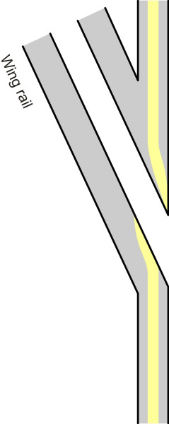
The English language names for the different parts of a turnout were established during the early nineteenth century (figure 12). The fixed rails on either side are called stock rails. Each switch-blade is tapered in plan and shaped in cross-section throughout its length (figure 13) to prevent a wheel climbing over the running surface. The V-shaped rail assembly where the closure rails converge is called the crossing. Here there are the gaps in the rails that allow wheel flanges to pass through. If the angle is large, the wheel tread will drop into the gap and make a considerable impact with the rail surface on the downstream side (figure 14). Hence the crossing undergoes heavy wear, and is often cast as a single unit in manganese steel. On the other hand if the angle is shallow the wing rails on either side prevent the wheel from falling into the gap: provided the wheel tread is reasonably wide, some part of it will be supported throughout. But because of the curved rail head profile, the contact patch deviates from its normal course and instead traces a characteristic zig-zag pattern in three dimensions (figure 15) with a dip in the vertical alignment, so that in practice, there is always a jolt. This is why the wheels make their familiar clicking noise whenever a train goes through a turnout. The guard rails or check rails are intended to prevent excessive lateral movement of the axle that might allow a wheel to emerge on the wrong side of the nose.
Figure 12
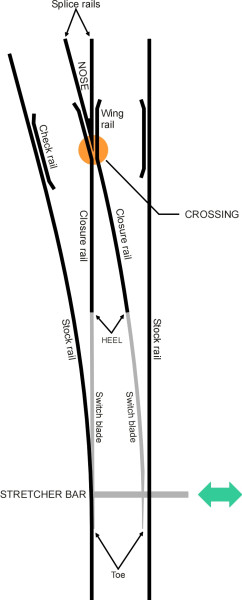
Figure 13
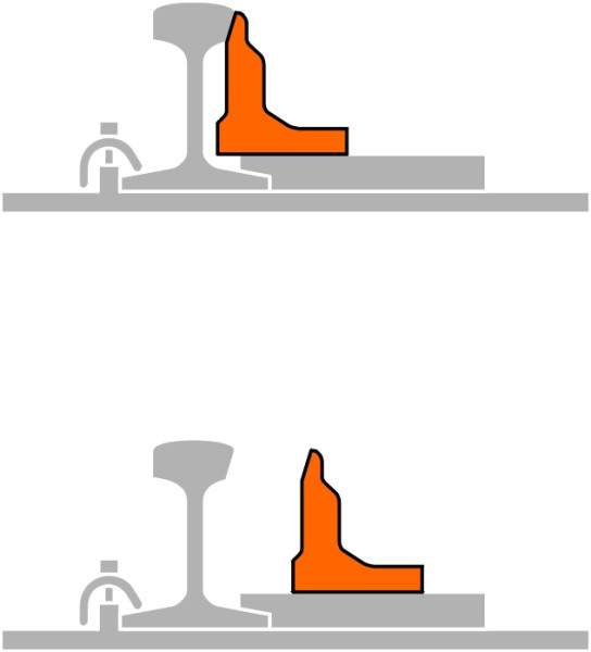
Figure 14
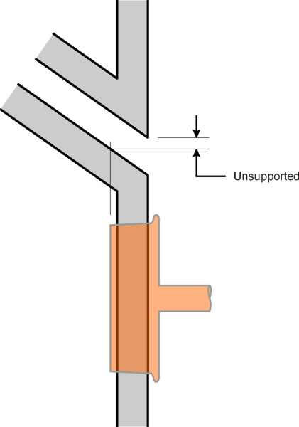
Figure 15
Actuation
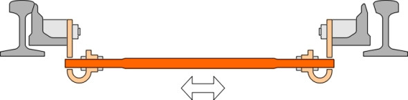
The two switch-blades are linked together by one or more stretcher bars\(\;\)that slide laterally under the stock rails (figure 16). In order to switch paths, one of the stretcher bars is moved either by an electric motor, or manually by a lever that may be located by the side of the track or in a signal box located some distance away. With manual signalboxes, strength and skill are required to ‘throw’ distant turnouts, but most of these have now been replaced by electrical systems. In a modern turnout, an electric motor moves the stretcher bar via a rotating shaft with a screw thread. It can be activated by a push-button, or electronically through an automated system under computer control. The stretcher bar moves the blades laterally so that when one is open, the other is closed against its stock rail. Typically the motor applies a force between 2 and 10 kN, usually enough to overcome any friction caused by detritus caught between the switch-blade and its supporting chairs, and in the closed position it is spring-loaded with a force of 2.5 kN [4]. Whatever the method of actuation, the turnout is protected by one or more safety locks. A simple form of lock comprises a metal tongue that slides into a hole drilled into one of the stretcher bars [2]. The locking pin does two things. First it can be used as a sensor, triggering a warning back to the signal box if it’s not fully home, and secondly, if the actuator fails it prevents the blade from being prised away from the stock rail by a wheel flange as it enters the turnout.
Figure 16
Not surprisingly, engineers are continuing to search for ways of increasing the service life of the crossing, where most of the wear takes place. Two recent developments are both aimed at smoothing or removing the gap in the crossing altogether. The first is to make the nose move from side to side as shown diagrammatically in figure 17. This is the system developed for use on the French SNCF; it can accommodate 160 km/h on the diverging path and 300 km/h on the ‘through’ alignment. It is also useful for reducing noise and vibration on urban railways through residential areas [1]. Another way of achieving the same effect is the ‘moveable point frog’ (figure 18).
Figure 17
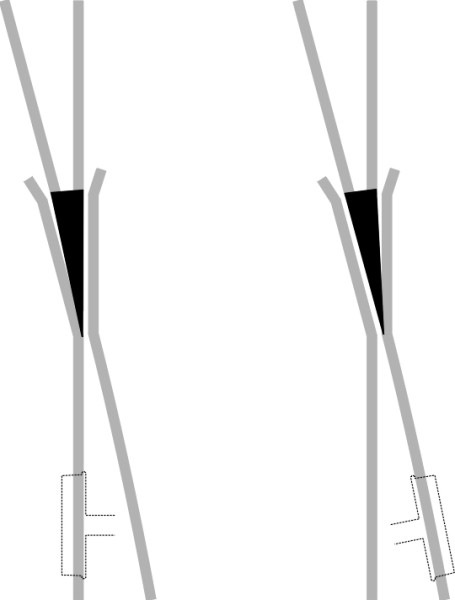
Figure 18
Conclusion
A turnout is a vulnerable and expensive piece of machinery. On a lightly-trafficked line, with careful maintenance it can last for 25 years, but at a busy junction on a main line it may have to be replaced every 12 months. The work is usually carried out at night to avoid disrupting the timetable. When travelling through a turnout at speed, the safety of a train depends on accurate alignment of the switch-blades and associated gear. A rigorous maintenance regime is essential, and it doesn’t necessarily involve high technology: just regular inspections to ensure the elements of a turnout are all in good working order. As we shall see in Section R0314, this doesn’t always happen.