R.0410
Tilting trains
Railway trains continue to evolve from one generation to the next. But the tracks evolve more slowly: they were laid down in the nineteenth century and the layout hasn’t changed much since. To avoid expensive structures like bridges, cuttings and tunnels, the early railway builders made the tracks twist and turn so they followed the contours of the landscape. They were soon hemmed in by houses and factories built alongside during a period of industrial expansion and population growth. Meanwhile, the technology of steam locomotion continued to develop, and fifty years later, trains were capable of higher speeds than the alignment could safely handle. To reduce the risk of damage and derailment on sharp curves, the railway companies imposed speed restrictions that effectively limited the performance of express services across the network. Today, vehicles are not only lighter but have acquired a lower centre of mass together with better steering, so the risk of overturning or derailment is much reduced. Modern track is better able to resist lateral forces, and although high speeds lead to higher rates of wear, in principle a modern vehicle is capable of travelling round a curve much faster than its predecessors without actually falling off or damaging the rails. But will passengers enjoy the experience?
Why tilt?
We human beings cope with the force of gravity quite well, through a structural skeleton that carries our weight vertically to the ground, and we keep our balance through sensitive nerves in the soles of our feet together with balance organs in the skull that detect small deviations from a vertical posture. But we are less well adapted to handling lateral disturbances. When travelling on a curved path, each part of the human body including the greater mass of the torso must be accelerated laterally towards the curve centre. We need to be pushed sideways. When we are sitting inside a train, without having to adjust our posture greatly we can acquire the acceleration from a combination of sources such as the seat squab (cushion), the seat back, and arm rests. It’s more difficult for a standing passenger. One can lean against a partition or grab a handhold, but when there is no handhold the lateral force is channelled entirely through one’s feet and it is difficult to avoid stumbling or falling over.
It follows that if trains are to go faster without compromising passenger comfort, the engineer must find a way to alleviate the centripetal forces. Cyclists and horses do this naturally by leaning inwards so the centripetal force is balanced by their body weight (see Section C2009). Can a railway train be made to do the same? At one time, the idea of a railway train that could lean over like a cyclist would have seemed outlandish, but after many trials and at least one major failure, tilting trains have been made to work successfully, and some have been in operation for more than 30 years [2].
The passenger’s frame of reference
To understand what is going on, we’ll need to look back at Section R1604. Figure 1 represents the cross-section of a train travelling at a constant speed \(V\) round a curve of radius \(R\) on non-canted (level) track. It shows the reactions acting though the feet of a standing passenger in contact with the cabin floor. We assume the vehicle doesn’t roll on its springs, so the floor remains parallel to the track. The black arrow labelled \(Mg\) represents the vertical reaction arising from the passenger’s body weight, while the horizontal black arrow labelled \(C_{1}\) represents the centripetal force that maintains the passenger on a curved path, and is equal to \(MV^{2} / R\). A passenger standing in the gangway with no lateral support would be obliged to lean at an angle \(\delta_{1}\) to avoid falling over, and this angle represents the cant deficiency from the passenger’s point of view.
Figure 1
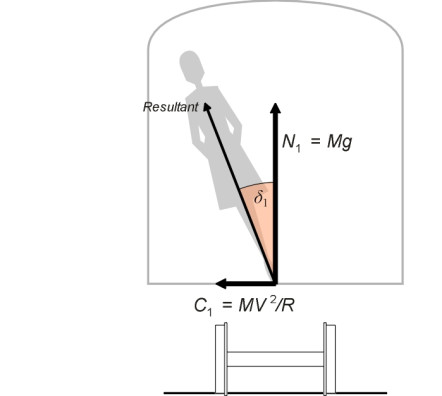
Figure 2
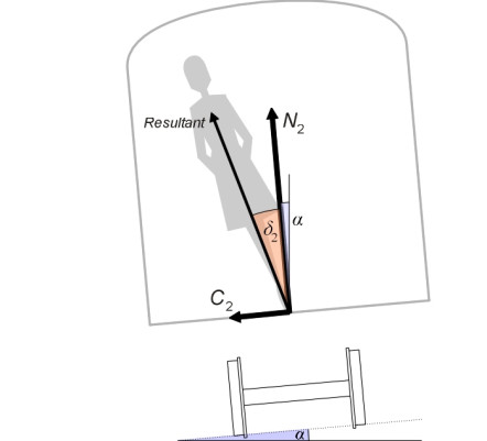
Figure 3
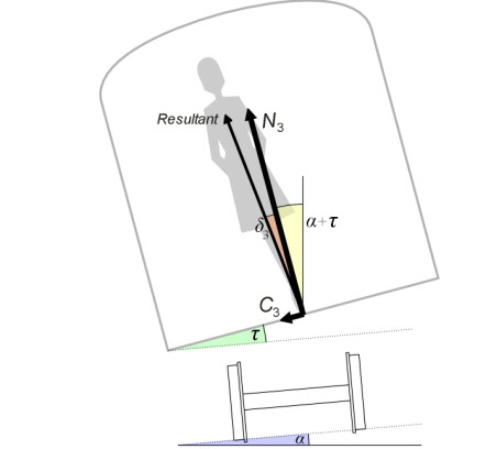
Figure 4
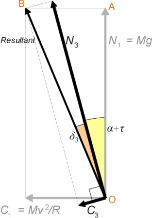
In figure 2, the track is canted at an angle \(\alpha\) to the horizontal. This reduces the cant deficiency to a new value \(\delta_{2}\), because the passenger has a new frame of reference with the cabin floor sloping at the same angle \(\alpha\) as the track. The passenger perceives a ‘vertical’ reaction to his or her body weight at right-angles to the floor equal to \(N_{2}\), together with a ‘lateral’ force \(C_{2}\) parallel to the floor. The lateral force is reduced. But we can go one step further and tilt the cabin through an angle \(\tau\) relative to the track. The cant deficiency becomes \(\delta_{3}\), and the perceived lateral force, indicated by the arrow labelled \(C_{3}\) in figure 3, is reduced further still. Figure 4 shows the configuration of forces in more detail. Resolving parallel to the cabin floor we see that
(1)
\[\begin{equation} C_{3} \quad = \quad \frac{MV^{2}}{R} \cos (\alpha + \tau ) \; - \; Mg \sin (\alpha + \tau ) \end{equation}\]so that
(2)
\[\begin{equation} \frac{C_{3}}{Mg} \quad = \quad \frac{V^{2}}{Rg} \cos (\alpha + \tau ) \; - \; \sin (\alpha + \tau ) \end{equation}\]and since \(\alpha\) and \(\tau\) are both small, to a close approximation this can be written
(3)
\[\begin{equation} \frac{C_{3}}{Mg} \quad \approx \quad \frac{V^{2}}{Rg} \; - \;\alpha - \tau \end{equation}\]As you might expect, each additional degree of tilt reduces the lateral force perceived by the passenger in the same manner as an additional degree of cant. Conversely, if you decide what is an acceptable lateral force and fix the value in advance, you can increase the speed of the train by canting the track and making the cabin tilt. We see from triangle OAB in figure 4 that
(4)
\[\begin{equation} \tan (\alpha + \tau + \delta _{3}) \quad = \quad \frac{C_{1}}{N_1} \quad = \quad \frac{V^{2}}{Rg} \end{equation}\]and since for a small angle the tangent is approximately equal to the angle itself this implies that
(5)
\[\begin{equation} \frac{V^{2}}{Rg} \quad \approx \quad \alpha + \tau + \delta_{3} \end{equation}\]which shows that other things being equal, each additional degree of tilt leads to an increase in the speed at which the train can operate on a curve of given radius.
The speed dividend
We can derive a neat formula for the ‘speed dividend’ from equation 5provided we fix in advance the angle of cant \(\alpha\) together with the desired level of passenger comfort specified in terms of the permitted cant deficiency \(\delta = \delta_{1} = \delta_{2} = \delta_{3}\). Let’s denote the allowable speed without tilt by \(V_{0}\), and the allowable speed with tilt by \(V_\text{tilt}\). From equation 5 we have
(6)
\[\begin{equation} V_{0} \quad \approx \quad \sqrt { Rg \left( {\alpha + \delta } \right)} \end{equation}\]and
(7)
\[\begin{equation} V_{\text{tilt}} \quad \approx \quad \sqrt { Rg \left( {\alpha + \tau + \delta } \right) } \end{equation}\]so the percentage speed increase on a curve of radius R is
(8)
\[\begin{equation} \begin{array}{l} \left( {\frac{V_{\text{tilt}} \; - \; V_{0}}{V_{0}}} \right) \times 100\% \quad \\ \\ = \quad \left[ {\frac{ \sqrt {Rg(\alpha + \tau + \delta )} \; - \; \sqrt {Rg(\alpha + \delta )} }{ \sqrt { Rg (\alpha + \delta )} }} \right] \; \times \; 100\% \\ \\ = \quad \left( {\sqrt { \frac{\alpha + \tau + \delta }{\alpha + \delta }} - 1} \right) \times 100\% \end{array} \end{equation}\]A typical example shows that the increase can be quite large. During the 1970s it was decided that the maximum tilt angle for the UK’s Advanced Passenger Train would be \(9^{\circ}\) [4]. On track with maximum cant 1:10 or \(6^\circ\), and given a maximum cant deficiency for passengers of \(0.07 g\) (equivalent to \(4^\circ\)), equation 8 predicts a speed increase of about 40%. However this increase would not be available across the whole network, only on curves where the tilt was applied. About half the UK mainline network consists of curved track [5], but some curves are so shallow that the potential maximum speed with tilt applied is beyond the reach of the fastest trains. For these curves, there is little benefit, and of course the benefit is zero on straight track.
Applying the tilt
The rationale for a tilting train is straightforward: it reduces the lateral acceleration for passengers and allows the service to run faster on curves. However, to design a successful scheme we must answer some practical questions:
- What should be the maximum angle of tilt?
- How quickly should the vehicle body rotate from the upright position?
- Where in relation to the vehicle cross-section should the centre of rotation lie?
- When the vehicle body tilts, what happens to the pantograph?
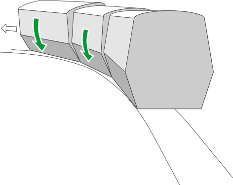
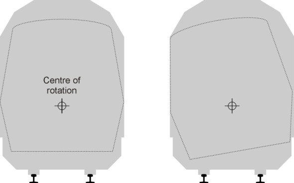
The first question is the most important because it dictates the operating speed of the service. In principle, one can fix the tilting mechanism so the passengers feel no transverse acceleration at all: the vehicle tilts as far as is necessary to maintain zero cant deficiency at all times. This is effectively how a cyclist behaves, or a galloping horse, or almost any creature running along a curved path. But if applied to a railway train it would entail a much smaller cabin, because as shown in figure 5, for a traditional coach body, every additional degree of tilt carries some part of the vehicle body outside the normal vehicle gauge. We’ll return to this point in a moment. It would also complicate gangway connections between neighbouring coaches, because they don’t tilt simultaneously. There is a delay in rotation as each successive coach enters a curve (figure 6), and the connecting doors and gangway floor must take up any angular difference. For both these reasons, the designer will limit the angle of tilt in such a way as to leave a residual cant deficiency even on shallow curves, and the proportion of transverse acceleration that is not compensated remains roughly constant, say 40%. This ensures that a passenger who is looking out of the window sees a consistent relationship between the severity of the curve and uncompensated acceleration.
Figure 5
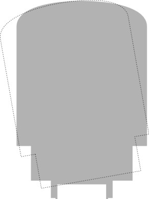
Figure 6
Which brings us to the second question. You might be surprised to discover how quickly and how sensitively the tilting mechanism must operate when the vehicle is travelling along a track designed for nineteenth century steam trains. Each significant change in curvature is preceded by a transition curve in which the radius varies smoothly so that passengers are not subject to excessive ‘jerk’ (a high rate of change of acceleration). A transition curve might be only 250 m long, and a wheelset on a high-speed train will cover this distance in 3 or 4 seconds. During this time, the coach body must rotate from zero to maximum tilt, and more important, the rotation must start almost immediately and adapt to the changes in curvature so that the proportion of acceleration that is uncompensated remains more-or-less constant throughout. Otherwise passengers will experience uncomfortable sensations that can lead to motion sickness. And because of the time lag between successive coaches mentioned earlier, the rotation must be applied individually to each in turn.
The third question has less to do with passenger comfort and more to do with fitting the vehicle into its trackside environment. As shown previously in figure 5, when rotated about any chosen centre, a coach with a conventional profile will not comply with the conventional vehicle gauge and it is necessary to taper the cross-section both above and below the centre of rotation. This suggests that the centre of rotation should be made to coincide with the level of the passenger seats, where the greatest lateral width is needed [4]. The result is a profile something like the one shown in figure 7, tapered at the top and bottom. You can see there is a substantial reduction in cross-sectional area.
Figure 7
The fourth question applies to electric trains that collect power from an overhead wire. The pantograph itself must not tilt otherwise it may lose contact with the wire, or even hook over the wire with disastrous results. In fact each pantograph must be equipped with an anti-tilt device that rotates the whole assembly in the opposite sense to the body-tilting mechanism (see picture in [6]). There is also the question of the drive shafts connecting the motors with the wheelsets. On modern electric vehicles, the motors are slung from the car body to reduce unsprung mass, and a flexible drive shaft is required to handle the variations in geometry when the body tilts on a curve.
A final point: since a tilting train travels faster on curves than a conventional train, other things being equal it will apply greater lateral forces to the outer rail and the rate of rail wear will increase. The increased maintenance costs can be offset to some extent through lighter construction to reduce the wheel loads together with self-steering bogies to reduce the flanging forces. Nevertheless, the life of a wheel for a tilting train is much shorter than that for other vehicle types [9].
Tilt technology
Humans and animals lean into a curve naturally and with seemingly little effort. A tilting train can do this if the suspension is arranged so that the centripetal force itself causes the passenger cabin to swing from side to side like a pendulum. A system of this kind is known as a passive system because it needs no actuating mechanism to make the cabin rotate. Otherwise the engineer must provide hydraulic rams to tilt the cabin, together with a control system to determine when and by how much. Such a system is called an active system.
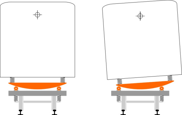
Passive mechanisms
The key to a passive system is to arrange the centre of rotation above the centre of mass so the cabin swings naturally from side to side, like a baby’s cradle suspended from a pivot at each end (figure 8). This would be a cumbersome arrangement for a cabin weighing twenty tonnes, and in practice, a high centre of rotation can be arranged more easily by other methods. One possibility is to provide a curved guideway at bogie level with rollers as shown in figure 9. This is the method used in Japan on the 381 series railcars, which were supported on two 170 mm diameter rollers at either end to give a modest tilt of \(5^\circ\) [8]. They went into service on the western section of the Chuo Main Line between Nagoya and Nagano in Japan in 1973. The system was later extended to other lines, but not always successfully because the response was too slow or too abrupt to deal with tight curves. It was replaced by an active system, first introduced in 1989.
Figure 8
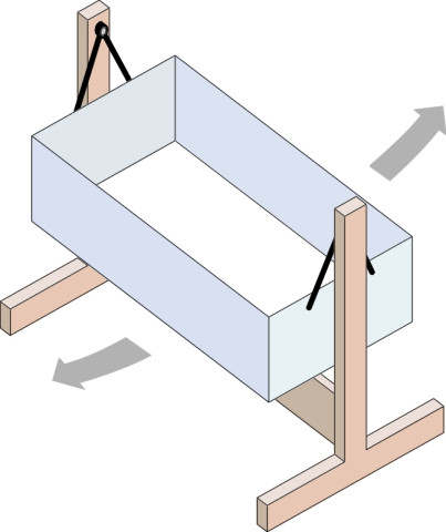
Figure 9
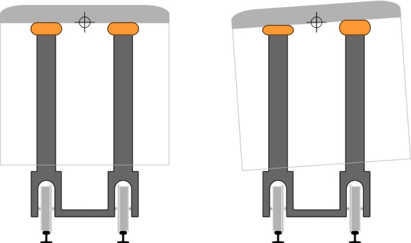
The Spanish company Talgo introduced tilting trains in 1980. The name Talgo stands for TrenArticuladoLigeroGoicoecheaOriol, a company founded by Alejandro Goicoechea and José Luis Oriol, who first patented their articulated passenger car suspension in 1941 (see the Talgo company web site [12] listed at the end of this section). The comparison with the Japanese tilting trains is interesting. The Spanish trains were equipped with a passive system too, but it worked in a different way. In fact the trains displayed many ingenious features that have been refined through several versions until the present day. The cars are articulated but the ‘bogies’ have only a single axle, and the wheels rotate independently. The axles are steered by links connecting them to the adjacent car bodies so they take up an angle in plan that bisects the longitudinal axes of the neighbouring cars. Each car is supported effectively at three points, two points at one end of the car and a single point at the other. The two-point support is provided by a secondary suspension at roof level with air springs mounted on tall pillars rising from the bogie frame as shown in figure 10. Hence the car body swings like a pendulum on each curve without the need for actuation rams (figure 11).
Figure 10
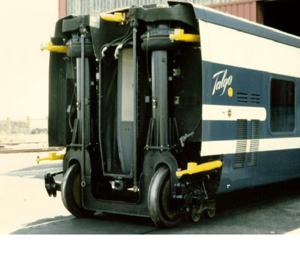
Figure 11
Active mechanisms
Unlike a passive system, an active system works through an actuating device that forces the body to rotate relative to the bogie by a controlled amount. The actuating device is usually a hydraulic ram of the kind you might see on a mechanical digger on a building site, but some vehicles have pneumatic rams (air-powered) and some have electro-mechanical actuators of the kind now favoured for aircraft controls. Since the system doesn’t rely on gravity to swing the cabin from side to side, the centre of rotation can be well below roof level, but on the other hand, it must still be above the centre of mass so that if the tilting mechanism fails the cabin tends naturally to settle into a vertical position. The four-bar link shown in figure 12 is a compact and efficient solution: the centre of rotation is not actually fixed but moves laterally through an arc as the cabin tilt increases. Nevertheless, by adjusting the lengths and angles of the two swinging links one can locate the arc at almost any chosen height above the centre of mass. (At this point you might want to refer back to Section C0414 which explains the concept of a roll centre and how to find it for a mechanism such as a four-bar linkage).
Figure 12
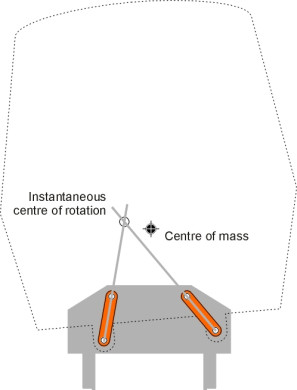
Figure 13
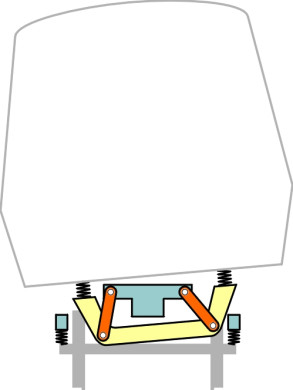
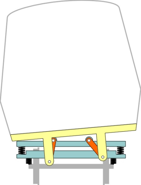
The next question is how to fit the tilting bolster and the secondary springs between the bogie and the passenger cabin. The layout chosen for the Advanced Passenger Train is shown diagrammatically in figure 13. The bogie frame was constructed around a central spine and the tilting bolster passed underneath it. The secondary airbags were mounted above the bolster with the cabin on top. More detailed drawings of the layout appear in [7]. The APT was abandoned before going into production partly because the control system could not drive the tilting sequence accurately and reliably enough to prevent motion sickness. The technology was sold to the Italian company that now makes the Pendolino trains that have run successfully in Italy and the UK for some years. Using a different suspension arrangement, an earlier version of the Pendolino went into service in Italy in 1988, the first active tilting train to do so [11]. The suspension for the current generation of Pendolino trains uses swinging links like the APT, but the secondary springs are mounted below the tilting bolster on either side of the bogie (figure 14). Forced tilt was introduced on Japanese railways in 1989 on the Shikoku DMU series 2000 trains, actuated by air cylinders [8]. A useful summary of many of these options including diagrams and drawings is available on the world wide web [1].
Figure 14
Control schemes
An ‘active’ tilting mechanism needs a control system to decide how much tilt is needed and when it should be applied so that the uncompensated lateral acceleration is set at a level consistent with passenger expectations at each point along the track. There are two possible sources for the information needed by the system to achieve this. The first is a gyroscopic sensor or accelerometer that detects lateral acceleration, together with a microprocessor control unit that directs the hydraulic rams to apply tilt accordingly. Usually, there will be one unit per car. Unfortunately, there is a finite delay while the system detects a cant deficiency and the rams go into action. A further period is needed for the rams to overcome the rotational inertia of the vehicle body. Moreover, the detector cannot be too sensitive otherwise it will pick up random motions arising from irregularities in the track alignment and feed them into the controller, causing the actuators to adjust the angle constantly to no useful purpose. Hence the tilt response will inevitably lag behind the cant deficiency, and to counter this, the control system for each coach is usually programmed to act on the signals from the coach immediately in front [3]. The second possible source of control information is external: the track curvature can be signalled in advance through a balise located before the start of each curve. This is the system used on some Japanese tilting trains [3] [10].
Conclusion
The cabin of a passenger coach may be 25 m long and weigh 20 tonnes excluding the bogies. Even today, the idea of mounting a structure of this kind between two pivots and equipping it with complicated hydraulics and motion sensors to make it swing through a few degrees seems ambitious. The task of developing a system that would tilt smoothly and reliably was not an easy one, and at least during the early years, the rate of progress was not reassuring. In the UK, an intensive development project led by the national rail company ran into difficulties, and although the mechanical challenges were overcome, the control system proved inadequate and the programme was abandoned after a few highly publicised trials. Meanwhile in Japan, engineers succeeded in making a passive system work, and the vehicles were eventually converted to ‘active’ operation driven by pneumatic rams. In Spain, a completely different passive system had been developed by the Talgo company to take advantage of its remarkable single-axle bogies, while in Italy, the early Pendolino trains finally overcame the problem of active control. Today, most of the world’s mature railway systems have tilting trains in operation, although they figure less prominently in France and Germany, where high-speed lines are being built on new alignments that don’t justify the expense and complication of tilt technology. For the time being, tilting trains work best on older railway lines where the geometry is less than ideal. However, if speeds continue to rise over the next few decades we may eventually see trains capable of much greater angular rotation. Riding in a train could be more like flying in an airliner: from time to time we’ll look out of the window and notice with a frisson of surprise that the world has shifted on its axis with the horizon looming at an unlikely angle. Or maybe we’ll see a digital image constructed within the window glass to reassure us that everything is in its proper place.
Acknowledgement
Figure 10: Picture appearing on Talgo Incorporated US web site www.TalgoAmerica.com, no longer available (accessed 27 November 2014).
26 January 2015