R.0314
Off the rails
Rail travel is one of the safest ways of getting about, much safer than riding in a car or bus. But if a train breaks the speed limit or runs over damaged or misaligned track, it is possible for a wheelset to jump the rails. In a severe case, a bogie and possibly a whole coach will slew off the track, and since each coach is coupled to its neighbours, it may drag others with it. At this point, there is a risk of collision with trackside objects, and on a two-way line, with a train coming in the opposite direction. Fortunately, accidents on this scale are rare, so much so that they make news headlines that are broadcast around the world. But surprisingly perhaps, minor derailments are common, and whether or not anyone is hurt, a derailment blocks the line until a rescue crew arrives to lever the offending vehicle back onto the track. If a derailed freight wagon is dragged over a long distance before anyone notices, the track may be so badly damaged that it takes several days to get the line back into operation. With over 3000 derailments per year reported in the USA for example [15], the costs are considerable, and in this Section, we review the different causes of derailment and measures for preventing it.
Derailment
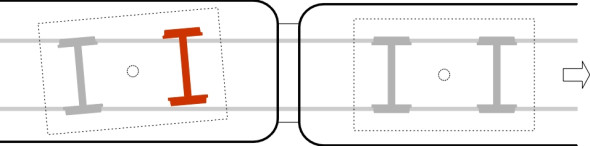
A derailment occurs when a wheel falls off the running surface of the rail on which it is supposed to be travelling (figure 1). The leading axle of a bogie is more vulnerable to derailment than the trailing axle, and usually, the displaced wheel or wheels will bounce along the sleepers, creating intense vibration and potentially causing a great deal of damage. There is no single predominant cause; rather, the risk is influenced by a number of factors including the condition of the wheelsets and the state of the track. Derailments at high speed and derailments at low speed tend to occur under different circumstances.
Figure 1
Let’s look at high-speed derailments first. High-speed derailments tend to arise when the centripetal forces between vehicle and track are greater than those the system is designed to handle, either on a curve or at a turnout where the path of the train diverges from a straight track. A crash of this kind occurred on the Spanish rail network between Madrid and Ferrol in 2013, when an intercity Talgo train derailed on a curve at 192 km/h, more than twice the local speed limit. The results of taking a curve too fast vary from case to case: for example the wheels may force the rail onto its side, the track may shift bodily out of line, or the vehicle may simply overturn. Derailment can also occur on straight track with vehicles that are prone to hunting, such as empty freight wagons [22].
Of course, a derailment can arise at any speed if there is a mechanical failure at a turnout, such as a loose stretcher bar or jammed blade. But derailments at low speed occur most commonly when the vehicle lurches sharply to one side and a wheel climbs over or ‘jumps’ the rail. The risk is greatly affected by a defective track alignment, of which there are three main categories: gauge widening, track panel shift, and twist. Before going on to describe them we’ll look at the wheel climbing process more closely.
Flange climbing
For most of the time, a railway wheelset will steer itself along the track without either flange touching the rails. The purpose of the flange is to prevent the wheel from falling off the rail surface when buffeted by lateral forces, or when it encounters a kink in the track alignment. However, the flange doesn’t always work. Figure 2 shows the leading outer wheel of a bogie rolling from left to right along a curved rail. The wheel carries roughly a quarter of the total load carried by the bogie, and it transmits the load vertically to the rail through the contact patch, shown as a white disk and labelled ‘A’ in the diagram. But as we saw earlier in Section R0415, on a sharp curve the flange doesn’t run parallel to the rail but ‘attacks’ it at a small angle and presses sideways against the rail shoulder, so that a second area of contact develops indicated by the red disk ‘B’. The disk B lies slightly ahead of the disk A by an amount \(h\) as shown in figure 3. And within the second contact area B, at any given moment the surface of the flange is actually moving downwards relative to the rail shoulder as shown in figure 4, and owing to the friction between them, the contact centre acts as a pivot around which the wheel levers itself upwards in an arc centred on B (figure 5).
Figure 2
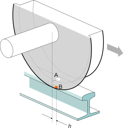
Figure 3
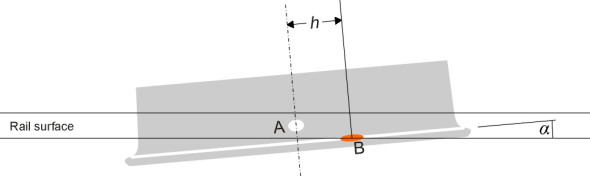
Figure 4
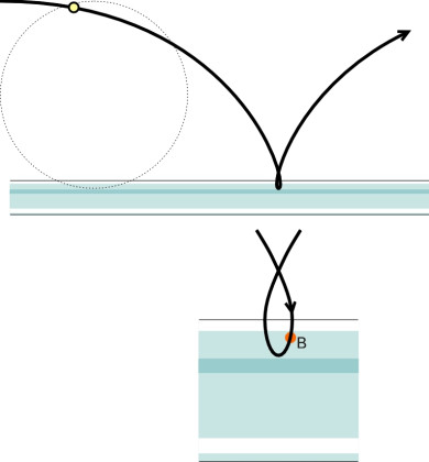
Figure 5
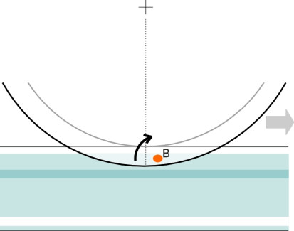
Figure 6
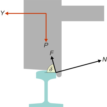
Of course, this won’t happen when the vehicle is standing still - the wheel must be rotating. At first glance, the geometry seems complicated but if we assume static equilibrium at the moment when the wheel starts climbing we can work out the forces acting on the wheel and thence a criterion for predicting when flange climbing is likely to occur. We consider the angle of attack to be sufficiently small that all the forces can be treated as acting within a plane at right-angles to the track. In figure 6, the angle \(\delta\) is the angle to the horizontal of the contact surface. The red arrows represent the forces applied to the wheelset by the vehicle body it supports: the vertical wheel load \(P\) and the lateral ‘flanging force’ \(Y\). The black arrows show the reactions at the rail surface: (a) a friction component \(F\) tangential to the flange contact area, and (b) a component \(N\) normal to the flange contact area. Resolving vertically, we see that
(1)
\[\begin{equation} P \quad = \quad N \cos \delta \; + \; F \sin \delta \end{equation}\](2)
\[\begin{equation} Y \quad = \quad N \sin \delta \; - \; F \cos \delta \end{equation}\]Now let’s divide equation (2) by equation (1) to get
(3)
\[\begin{equation} \frac{Y}{P} \quad = \quad \frac{N \sin \delta \; - \; F \cos \delta }{N\cos \delta \; + \;F \sin \delta } \end{equation}\]and then divide the numerator and denominator on the right-hand side by \(N \cos \delta\) to get
(4)
\[\begin{equation} \frac{Y}{P} \quad = \quad \frac{\tan \delta \; - \; \left( {\frac{F}{N}} \right)}{1 \; + \; \left( \frac{F}{N} \right) \tan \delta } \end{equation}\]This equation describes the relationship among the forces when the wheel is just about to climb the rail, and hence the quantity on the right-hand side represents the largest value of the ratio \(Y / P\) that we can allow for safe running. To be useful in practice, we must work out the smallest value it can take, i.e., a lower bound. This occurs when the ratio \(F / N\) takes on its largest value at the limit of friction so that \(F = \mu N\). We can therefore substitute \(\mu\) for \(F / N\) and write equation 4 as a limiting condition thus:
(5)
\[\begin{equation} \frac{Y}{P} \quad < \quad \frac{\tan \delta \; - \;\mu }{1 \; + \; \mu \tan \delta } \end{equation}\]If satisfied, this simple criterion indicates that the wheel will not climb the rail. It is called the Nadal criterion after M J Nadal, the French railway engineer who first derived it in 1908. It has since been used throughout the world as an aid to assessing the likelihood of derailment on a sharp curve. For any given wheel load \(P\) (normally around 10 tonnes or 100 kN), it predicts the maximum flanging force \(Y\) that any particular combination of wheel and track can handle before the wheel begins to climb. You can see that if the flange angle \(\delta\) is small, the expression on the right-hand side is small and there is a correspondingly modest limit: a low flange angle increases the risk of climbing [19]. The friction coefficient matters too: the higher the friction, the higher the risk.
Experience has shown that a railway system can tolerate higher lateral flanging forces than the Nadal Citerion suggests, provided the curves are shallow and the wheelsets well maintained. Hence the criterion provides a useful safety margin against derailment [16]. However, the formula assumes that the wheel and rail are in static equilibrium. In practice, the duration of flange contact is important, and to make a more accurate assessment one must simulate wheel climbing as a dynamic process involving elastic deformation of the wheel and rail materials, inertia, and force variations arising from irregularities in the track alignment together with the motion of the vehicle. More on this topic can be found in [2], [9] and [17].
Track misalignment
To summarise, the conditions that increase the risk of a wheel climbing the rail are
- An appreciable angle of attack,
- A large flanging force \(Y\),
- ‘Unloading’ of the wheel (\(P\) is small)
- A worn wheel with shallow flange angle \(\delta\),
- A high coefficient of friction between the wheel flange and rail shoulder.
The first three are associated with track misalignment. We discussed the main categories of misalignment in Section R1604, and there are three main categories that figure prominently in derailments: track panel shift, twist and gauge spreading.
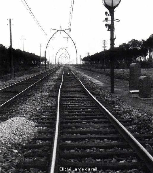
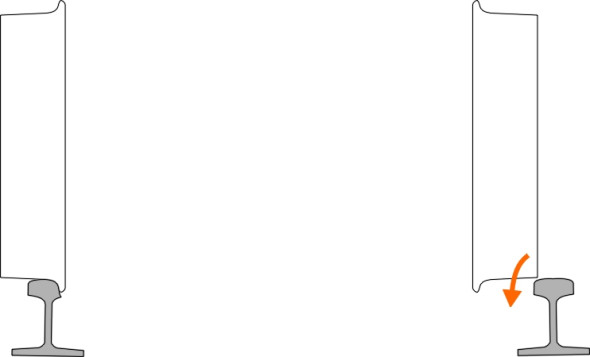
Track panel shift refers to the bodily movement of the whole track - rails and sleepers - out of its original alignment (figure 7), usually pushed sideways by the flanging forces exerted by vehicle wheels on the rail heads when negotiating a curve [21]. It can lead to local fluctuations in curve radius below the minimum level that trains can safely negotiate. Track panel shift may also occur on straight track, as happened during an electric locomotive world record run of 331 km/h in 1955 [6] [18]. The cause was probably a combination of (a) unstable hunting motion of the vehicle, and (b) the fact that the track ballast had been tamped just before the record attempt (tamping reduces the ability of the track to resist lateral forces). Figure 8 shows a photo of the track after the record run [24].
Figure 7
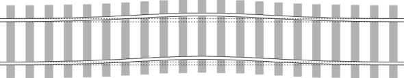
Figure 8
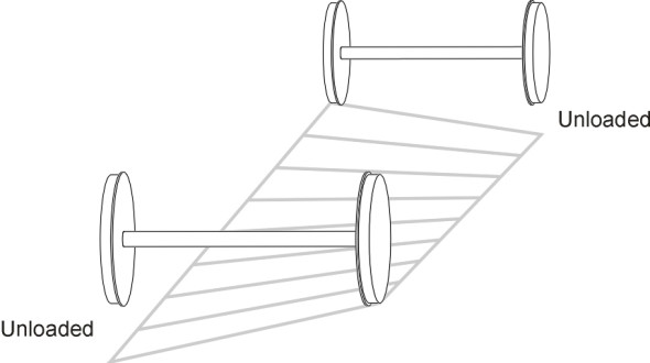
Twist is a different kind of misalignment that takes place in three dimensions, as described in Section R1604. It has the effect of reducing the vertical loads carried by wheels at diagonally opposite corners of a 4-wheel bogie (figure 9). If the leading outside wheel ‘unloads’ on a curve, this can lead to violation of Nadal’s criterion because it dramatically reduces the lateral flanging force that the wheel can sustain without climbing the rail. Twist is a frequent cause of derailment at low speeds [12].
Figure 9
Gauge spreading or widening refers to the condition in which the distance between the rails is larger than it should be, making it possible for one of the wheels to drop between them. It is most likely to arise on a curve where the flanging force accelerates wear on the inside shoulder of the outer rail (figure 10). The effect is compounded by a worn wheelset [20].
Figure 10
Other track defects
As we saw earlier in Section R1605, cracks will occur from time to time in a steel rail. If a crack grows unnoticed until it reaches a critical size, the rail will break, and under a series of impacts from the wheels, the loose ends can become dislodged. On 17 October 2000, on a curve of radius 1500 m near Hatfield in the UK, the outer rail broke under a train travelling from London to Leeds at about 200 km/h. The central group of coaches detached from the leading coaches and overturned, resulting in four fatalities. Triggered by rolling contact fatigue at the gauge corner, cracks had accumulated in the outer rail, which shattered in many pieces over a length of the order of 20 metres. This was one of a series of accidents in the UK over a ten-year period that raised fundamental questions about who was ultimately responsible for railway safety, and the legal liabilities of railway staff. There followed a nation-wide programme of rail refurbishment that almost brought the system to a halt, together with new legislation together and a re-structuring of the organisation responsible for the national rail network [1] [3] [4] [7].
Figure 11
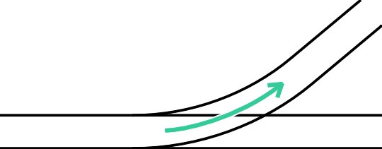
Figure 12
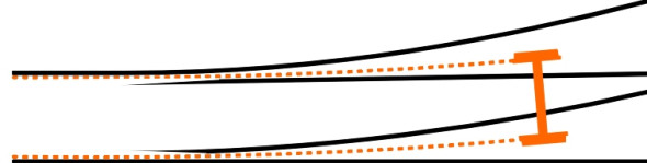
The last category of track defect concerns damaged or defective turnouts. Turnouts attract a disproportionate number of rail crashes because they contain sharp curves. Hence speed is a critical factor, especially on facing turnouts where the vehicle has two alternative exits. On a high-speed network, the main line usually runs straight ahead and the ‘ahead’ path can be taken at maximum speed. However the diverging route follows a sharp curve (figure 11) that can cause difficulties for a fast-moving train. Derailments can also occur owing to mechanical failure. If the points are not properly locked in position, there may be a gap between each switch-blade and its corresponding stock rail (figure 12). When an approaching wheelset ‘splits the points’ it will derail, which explains why modern turnouts have safety locks built into the layout that ensure the points are correctly set in agreement with the signals. However, they rely on the mechanical integrity of stretcher bars that link the blades, and no amount of electronic locking can compensate for a missing or broken stretcher bar, or missing bolts that are meant to secure the stretcher bar to the switch-blades. Missing bolts were a factor in the 2002 disaster at Potters Bar near London, and subsequently in 2007 at Grayrigg in the north-west of England, where all nine coaches of the 1715 London – Glasgow Pendolino derailed, resulting in many injuries [5] [13]. Patent locking nuts were later introduced by the network operator.
Rollover
In Section C1508 we showed how a road vehicle can overturn when carrying out an extreme manoeuvre. Something similar can happen to a rail vehicle, and although a railway engineer wouldn’t normally classify overturning as a derailment, we include it in this Section for convenience. The outside wheels do not jump the rails, but rather, the vehicle as a whole pivots about them under the action of centripetal force, so the inside wheels rise into the air and the vehicle tips on its side. Today, such incidents are rare: with the motors slung underneath the vehicle body, modern vehicles have a low centre of mass and require a high lateral acceleration to make them overturn. But this was not the case a hundred years ago. The problem was the large mass of water contained in the boiler of a typical steam locomotive, which couldn’t be fitted between the driving wheels on standard gauge track (figure 13). The high centre of mass caused many ‘rollover’ accidents, usually at turnouts [14].
Figure 13
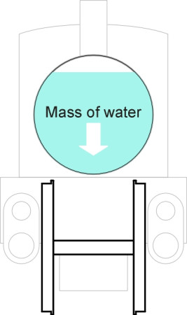
Figure 14
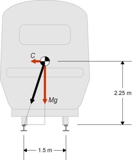
It is easy to estimate the centripetal force under which a vehicle will overturn, and to derive a factor of safety that enables one to compare the risk to different kinds of vehicle operating at different speeds. Let’s consider the example cited in [10], where the centre of mass of a vehicle running on standard gauge track lies 2.25 m above the rail surface (figure 14). The centripetal force is denoted by \(C\) and the weight of the vehicle by \(Mg\). The inside wheel lifts off the rail surface when the resultant force passes through the centre of contact between the outer wheel and the rail. By similar triangles,
(6)
\[\begin{equation} \frac{C}{Mg} \quad = \quad \frac{0.75}{2.25} \quad \simeq \quad 0.33 \end{equation}\]so \(C\) must be \(0.33 Mg\) and the centripetal acceleration \(0.33 g\). If the operating speed is fixed so that the centripetal acceleration never exceeds \(g / 10\), say, then
(7)
\[\begin{equation} \text{Factor of safety} \quad = \quad \frac{0.33g}{0.10 g} \quad \simeq \quad 3 \end{equation}\]In other words, the lateral acceleration would need to increase by a factor of three beyond the level normally encountered before the vehicle were likely to tip over. However this doesn’t take into account track cant and it doesn’t allow for eventualities such as a side wind [11] nor the extent to which the body might roll on its suspension springs. When a new vehicle is being developed it may be necessary to test its performance under real conditions, as was the case with the Advanced Passenger Train (APT) during the 1970s. A mock-up vehicle with similar weight distribution and suspension characteristics was built from scrap components and tested on a curve near Dover, the speed being increased gradually until it toppled off the track at a centripetal acceleration very close to the predicted value [8].
Conclusion
Railway companies devote a great deal of time and effort to making trains safe. While one can’t prevent derailments entirely, it is possible to reduce the risk to a very low level. At critical sites, liquid friction modifiers can be used to lubricate the rail surface in a controlled fashion and thereby reduce the likelihood of a wheel climbing the rail [23]. Elsewhere, progress can be made through closely controlled safety checks and maintenance procedures, for example by (a) renewing worn wheelsets, and (b) correcting the track alignment. Looking to the future, softer bogie suspension will improve steering so that the wheels present a smaller angle of attack to the rail shoulder. Track monitoring will continue to present an interesting challenge. Right now, the process takes place on two levels. First, ultrasonic detectors are used to check the rails for hidden flaws and cracks; together with ancillary equipment for checking ballast condition and track gauge, they can be operated from a moving vehicle, and the results are fed into a computer database that alerts the operating staff to defects. At the second level is the traditional form of track inspection in which maintenance staff walk along the track looking for signs of wear and tear. Inspections are required weekly or even daily depending on the frequency of traffic. They are expensive and vulnerable to error, so it is tempting to imagine a future in which robotic vehicles roam the network at night, gently shaking the rails to see whether the fixings are loose, and checking for missing bolts at turnouts. In practice, experienced staff rarely miss anything and if a lapse does occur, it may well occur further up the management chain. From time to time, accidents have occurred after a fault has been reported but no-one has done anything about it.
Acknowledgement
Figure 8: Picture by Mr Maufroid of the distorted track after a successful speed record record attempt by the French national rail company SNCF, as it appeared in an article by journalist Charles Billy [24].
29 November 2014