R.0204
Train formation
When you drive along the highway, you will want to keep a safe distance from the vehicle in front and you’ll want a clear gap on either side. All this takes up a surprising amount of space. Any economist will tell you that empty space is wasted space, and one can get more value out of the highway system by joining vehicles together. For example, each truck can tow a trailer. A trailer confers two advantages: first, the operator delivers two loads with one driver, which halves the staff costs, and second, two vehicles joined together take up little more space than one because the trailer doesn’t need a safe gap in front. Hence, coupling vehicles in pairs will almost double the capacity of the highway. The same applies to other forms of transport such as canals and railways. Railways have the unique advantage that users can join together vehicles in much larger numbers to get a much larger saving. It is almost as easy to drive a train of ten coaches as a single railcar, so per hectare of land, the capacity of a railway line to handle traffic is potentially huge. A twin-track railway can serve around 10 trains per hour in each direction, and if each train carries 1000 passengers, the overall throughput comes to 20 000 passengers per hour, more than twice the capacity of a six-lane motorway. Of course, it’s not quite that simple. Trains must be assembled from vehicles of the right kind in the right order, and when vehicles are joined together in large numbers, they don’t always behave as you might expect. In this Section we’ll ask why, and explore some of the practical implications.
Marshalling the train
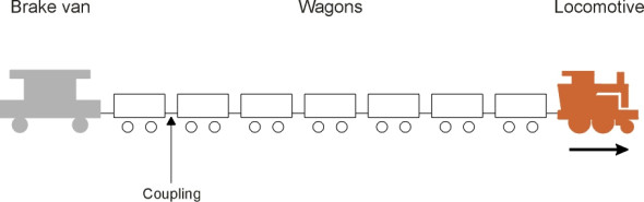
A train consists of one or more vehicles connected together and moving under the control of a single driver. The vehicles can be passenger coaches or freight wagons, or occasionally a combination of both. It will be propelled by a locomotive, or alternatively motors built into the vehicles themselves. In earlier times, a freight train would include a brake van at the rear (figure 1). Today, most wagons are fitted with air brakes and the brake van is no longer needed, but the order in which the vehicles are ‘marshalled’ is still important. The driver and the controls need to be at the front so the driver can see where he or she is going, and while the power source that keeps the train moving is often located close to the driver, this is no longer necessary and nor is it ideal for a fast-moving train. And the wagons need to be assembled in the right order, because once they are coupled, it’s difficult to add vehicles to or remove them from the middle of the formation.
Figure 1
What trains are made of
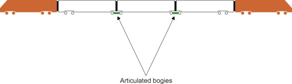
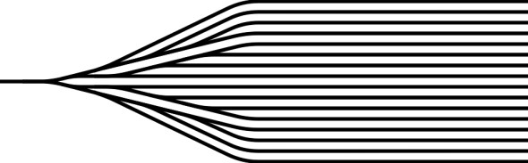
Passenger trains and freight trains differ in many ways. Let’s start with size. On the whole, passenger trains are shorter, usually between 2 and 12 coaches long compared with 20 or more wagons in a freight train. Ultimately, the length of a passenger train is limited by the length of the platform at the stations it serves, and since passenger coaches are generally about 20 m long, a high-speed service with 8 trailer coaches will measure a total of 200 m in length including power cars. The Brussels-Paris-London Eurostar with 18 trailer coaches is exceptional, having a total length of 400 m. Most high-speed trains need a large rectifier bank together with other equipment that cannot easily be fitted underneath the passenger coaches; they are usually provided with separate power cars, one each at the front and rear (figure 2). The set of coaches in between is called a rake. Each coach will seat between 40 and 50 passengers, so an 8-coach rake will carry up to 400 in total. Many of the coaches are designed to provide specific functions (such as the restaurant car) and will normally be coupled in a specific order. If the coaches are articulated (figure 3) they cannot easily be separated except at the maintenance depot. Articulation has the advantage [22] of eliminating overhang at the end of each passenger cabin and damping down relative motions between neighbouring cars, which improves the quality of the ride. And since for each coach there are only four wheels in contact with the rail (only two in the case of the Talgo trains), the train makes less noise. On the other hand, articulated bogies are more complex to build and maintain, the wheel loadings are higher, and since a fault effectively disables the whole rake, scheduling becomes more difficult.
Figure 2
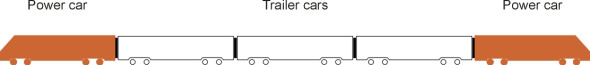
Figure 3
Articulated bogies are normally confined to high-speed trains. By comparison, regional trains must be more flexible. And they are lightly built and more sparsely furnished because they carry more passengers per unit of floor area. A regional express will seat about 70 passengers per coach. A suburban service or metro will carry even more passengers - over 100 per coach during peak periods - but many will have to stand. In either case, if the track is electrified the motors will be slung under one or more of the passenger cabins so there is no power car as such.
So much for size: what about the weight? Typically, a high-speed passenger train with two power cars and 8 coaches seating a total of 400 passengers weighs around 400 tonnes. It doesn’t make much difference whether the coaches are loaded or empty. If you reckon each passenger at 75 kg including luggage [26], the total payload comes to 30 tonnes, less then 10% of the gross weight of the train. To put it the other way round, the dead weight is many times greater than the payload, roughly 1 tonne for every passenger [11]. This might seem excessive, but railway coaches are built with a robust and almost impenetrable shell so they protect passengers in the event of a derailment or a collision with a line-side object. And the weight per passenger is actually about the same as the equivalent figure for a jet airliner such as the Boeing 747, or an automobile, which weighs over a tonne and spends much of its life carrying only a single occupant.
Freight trains are a different matter. They fall into two distinct categories: those in the first category are made up of individual freight wagons each with its own specific origin and destination. Trains of this type are engaged in the traditional form of distribution, known in the UK as tripping. Those in the second category are block trains, trains made up from identical wagons hauled together from a single origin to a single destination. Tripping services require a flexible approach because the wagons must be capable of being coupled and uncoupled possibly several times during the journey. Trains in either category contain at least 20 vehicles and often stretch further than the eye can see. The maximum permissible length for freight trains in many European countries is normally 750 m, but this is modest compared with some of the trains that carry bulk loads in less densely populated regions. In Australia in 1996, a train 6 km long and hauled by 10 locomotives weighed nearly 60 000 tonnes [4], and there have been heavier ones since. On a reasonably level track the total weight can be increased almost indefinitely by linking up smaller units into larger ones: the locomotives are positioned at intermediate points along the train so the traction is distributed evenly and the coupling forces minimised. The intermediate locomotives are controlled remotely by radio. In practice, things are not quite so simple because as we shall see later, quite dramatic longitudinal forces can be set up in a long train that may cause damage unless carefully managed.
Assembling a passenger train
When railway lines were first built in Britain, no-one was sure how they would work. Passenger coaches were equipped with primitive wooden seats but no roof, and supported on two axles like the horse-drawn trucks that were used in the coal mines of the north-east. And like trucks, they were joined together in whatever order seemed convenient at the time. The main challenge was not to form the train but to build a steam locomotive powerful enough to haul it from one end of the line to the other. What would the locomotive look like, and how should the boiler, cylinders and control levers be arranged? From the earliest days, the driver was positioned at the rear end of the chassis with the smoke-box and funnel at the front, so the driver had a restricted view of the track ahead. If this seems puzzling today, the reason was that the crew had to stand close to the coal and water supplies that were carried in a separate tender towed behind the engine. It was towed behind because if pushed ahead it was likely to derail, a point to which we’ll return later. There was also the stability of the loco itself to be considered. As speeds increased towards the end of the nineteenth century it was found that a locomotive could become dangerously unstable, zig-zagging from side to side in a motion called ‘hunting’ (see Section R0418). Partly in order to damp down the oscillations and partly to guide locos round curves, designers added pony trucks to the front of the chassis. They helped to cure the stability and curving problems, but only when the vehicle was moving forward. The steam loco was a one-way beast.
This requirement made the business of train formation more complicated than it is today. If you wanted to run an express service starting from a mainline terminal, the locomotive that was scheduled to haul the train couldn’t be used to bring the coaches into the departure platform because it would be facing the wrong way as well as being at the wrong end of the train. It was therefore necessary to provide a second locomotive, usually a smaller shunting engine, to set up the formation. The express loco would arrive afterwards, reversing into the station to be coupled to the leading coach. The procedure for dealing with an arriving service followed a similar pattern but in reverse order. However this wasn’t always possible on a minor branch line with limited facilities, and the same locomotive was employed for the outward and return leg of each service. Here, the tank engine proved useful. The tank engine did not need a separate tender, and although not very fast, it could haul a few coaches quite happily in either direction without having to turn around in between. The only requirement at the remote terminal was a headshunt with two turnouts so the loco could run round to the opposite end ready for the return journey (figure 4).
Figure 4
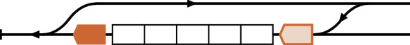
Figure 5
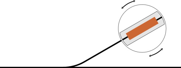
Figure 6
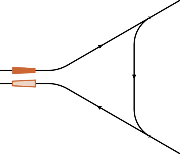
Figure 7
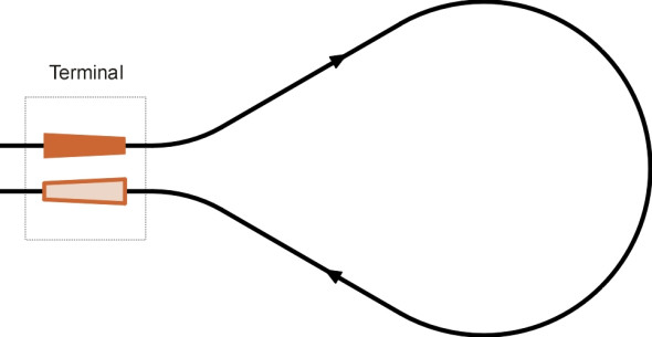
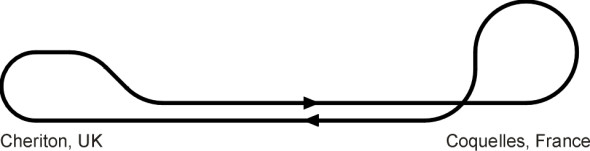
By contrast, faster locos with tenders were rotated through \(180^\circ\) so they could operate in either direction on a main line. There were several ways of doing this: for example, major depots were provided with a turntable (figure 5). Another method was to run the loco through a track section arranged in the form of a triangle with three turnouts as shown in figure 6, a facility that was usually available on a main line network within a reasonable distance of the terminus. In some cases, the terminus was provided with a balloon loop so the whole train could double back in an arc without uncoupling the locomotive at all (figure 7). A well-known example was the loop at Grand Central Station in New York. Today, almost all locomotives can operate equally well in either direction and such measures are not needed. But the Eurotunnel shuttle system between Calais in France and Folkestone in the UK is an exception. In order to maintain a high throughput, the trains are designed to run in a fixed direction on a continuous circuit. There is a balloon loop at either end, but because of the limited area of land available, the radius of curvature is relatively small, which causes appreciable wear of the wheel treads and flanges on the outside of the curve. To counter this, the track is actually laid out as a figure-of-eight as shown in figure 8, so the balloons are opposite-handed and the wear is more evenly distributed between the wheels on either side of the train (see the web site [29] listed at the end of this Section).
Figure 8
However, conventional passenger trains today are usually made up of fixed-formation rakes with a driver’s cab at each end so the train as a whole can shuttle backwards and forwards between terminals without having to turn round. Regional and local services are often built up from two or more complete sets so that the formation can be divided en route. One set continues on the main route while the second diverges onto a branch line. The division takes place at the station immediately upstream of the junction. It’s not an ideal arrangement because passengers sometimes find themselves in the wrong part of the train and have to scramble along the platform to avoid being taken to the wrong destination. Even more exciting is the practice of trains dividing on the move. At one time it was not unusual for express services to shed coaches from the rear of the train at intermediate stops without the main body of the train losing speed. In 1914, there were 200 services in Britain that operated in this way, and the practice only ended in 1960 [17]. The process only worked in one direction. No-one has yet discovered a way of assembling a train at speed even under computer control.
Freight operations
By comparison with passenger trains, freight trains have always been noisy, dirty and slow. The traditional railway distribution process is known as tripping. Each consignment is loaded onto a general-purpose wagon, and the routing of individual wagons is based on the hub principle. Wagons are collected from their respective rail heads by a small diesel loco, either individually or in small groups, and taken to a nearby marshalling yard, where they are sorted into larger trains each bound for a particular destination. The sorting operation takes place within a group of sidings or ‘classification tracks’: parallel tracks that branch out from a single approach (figure 9). When a train arrives, the loco is removed and the wagons are parked on the approach. A shunting engine then pushes the rake back-and-forth, each time dropping off one or more wagons into the appropriate siding; the wagons in each siding are then made up into outbound trains. Sorting consignments in this way is a slow process. Hauling them to the next stage can be a slow process too, because, as we’ll see later, empty wagons have a propensity to jump the rails and loaded wagons to break apart, so they are rarely allowed to travel at more than half the speed of a mainline passenger train. The slow travel speed together with time lost in the shunting yard means that it often takes more than a day to transport a cargo over a relatively short distance - an average of roughly 100 km in the UK [13].
Figure 9
The sorting process can be speeded up by rolling the wagons one after the other down a slope and switching each wagon separately onto its classification track, the turnouts being controlled from a central control box. During the twentieth century, a proportion of freight yards were converted to operate in this way, and for a while they were successful although demand has since declined. From the 1960s onwards, tripping operations suffered through competition with road transport, not least because a lorry can deliver from door to door whereas a shipment by rail will usually begin on a lorry and finish on a lorry with at least two transhipment operations in between. In future, it is conceivable that wagons can be shunted automatically by vehicles under remote control [16] [28], and as we’ll see later, other developments are being considered. But in many countries, the decline has been offset by growth in block trains. Block trains are used for transporting in bulk, for example gravel, iron ore, grain, refrigerated food, and containers. The wagons that make up a block train are specialised to the extent that they are all built to the same specification, which is tailored to the cargo they are carrying. An example of extreme specialisation might be the supply of coal from a stockpile to a power station. For many years now, trains have been operating this kind of service like a conveyor belt on a continuous circuit, loading and unloading while creeping along under electronic control at a little under 1 km/h [9].
Longitudinal dynamics
A railway wagon is a simple contraption, and like any other vehicle, it obeys Newton’s laws of motion. For example, if you pull steadily on one of its coupling it will pick up speed, accelerating at a rate proportional to the applied force. Yet when joined together in a train, wagons sometimes appear to take on a life of their own, jostling one another like unruly children. Their group behaviour emerges from the way they are connected. A certain amount of slack is built into the couplings, so that when an impulse is applied to any one vehicle, the vehicle transmits the event to its neighbours only after a short delay. As a result, considerable forces are set up between adjacent wagons that unless carefully managed, can be large enough to compromise the stability of the train.
Forces between wagons
Let’s begin by imagining a conventional freight train hauled by a loco at constant speed along a straight, level track. Under these conditions, the whole train will be in tension because each wagon has a certain resistance to motion and exerts a retarding force on the train. The retarding force arises from air resistance and rolling resistance as described in Section G0119. At a speed of 50 km/h, the resistance is quite small, about 18 N per tonne [10]. So the total resistance for a wagon whose gross weight is 50 tonnes comes to about 0.9 kN. For the moment let’s just call it \(S\).
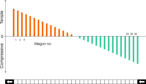
Under these conditions, the tensile force acting on each coupling between adjacent vehicles is steady and predictable. Suppose there are 30 wagons in the train, numbered 1 to 30 from front to rear. The last wagon needs a steady force of \(S\) to keep it moving at the stipulated speed, so the tension in the coupling between wagon number 29 and wagon number 30 is just \(S\) (we’ll adopt the convention that tension is positive and compression negative). Similarly, wagon number 29 requires a force of \(S\) plus the force \(S\) required to haul along wagon 30 behind, so the coupling force between wagon 29 and wagon 28 is \(2S\) newtons. The coupling force rises in equal increments from the rearmost coupling to the leading coupling on wagon number 1, where it peaks at \(30S\) newtons. The variations in coupling force along the train are shown diagrammatically in figure 10.
Figure 10
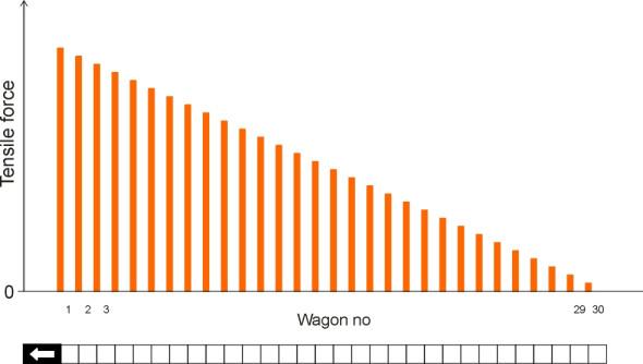
Figure 11
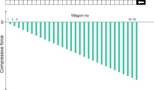
So what happens if the loco is coupled to the rear of the train and pushes the wagons instead? The profile of coupler forces is reversed, with the force between neighbouring vehicles increasing from front to rear as shown in figure 11. The peak force occurs between the loco at the rear and wagon number 30, and this time it’s compressive so we write it as \(-30 S\) for a train of 30 wagons. (Note incidentally that compressive forces between vehicles don’t always act through the coupling in the way that tensile forces do. For example, with old-fashioned screw link couplings of the kind still used in the UK and Europe, the links are not rigid. They carry only tensile forces, and therefore any compression force must pass through the buffers.) Now, since any wagon can be marshalled into any position during its working life, its couplings must be capable of handling the maximum tensile and compressive loads likely to be experienced anywhere in a train. For the train in question, consisting of 30 wagons each with a resistance of 0.9 kN, the steady-state force owing to rolling resistance on a level track is about 26 kN, not a huge amount. But it greatly increases on an uphill gradient; if the slope is 1.5% the loco must overcome a component of the train weight that amounts to 0.015 x 1500 tonnes or 225 kN approximately.
Moreover, in practice the forces in the couplings fluctuate over wide range. Fluctuations or shock loads can be several times higher than the static loads, which explains why standard screw couplings on European freight wagons are designed to carry loads up to 850 kN [2]. And since repeated shock loads tend to encourage fatigue cracks, it is better to keep the loads within more conservative limits.
Mexican wave
During a dull passage of play, spectators at a football match will sometimes take part in a ‘Mexican wave’. Taking their cue from the people sitting next to them, they rise from their seats, raise their arms in the air, and sit down again. This creates a ripple that travels round the arena at a characteristic speed of about 12 m/s [12]. Waves can travel along a freight train too: the motion is less obvious but if you live near a railway line you will have heard the melancholy clanking of the coupler chains at night. When a freight locomotive accelerates from a standing start there is a brief delay while the slack in the first coupling tightens, followed by another delay as the slack is taken up between wagon no 1 and wagon no 2, and so on. The effect is called ‘run out’. A similar effect occurs in reverse when a loco slows down: if the wagons don’t have air brakes, they will close up one at a time, ramming each other in turn to create a shock wave that passes along the train [5]. This is called ‘run-in’. The amount of slack depends on the type of coupling and tends to be greatest for the old-fashioned screw couplings used in Europe. Even if the wagons have air brakes they don’t all act at once. When the driver applies the brake lever, the signal is transmitted via a brake pipe at finite speed so there will be a delay in the actuation of the brakes on successive wagons. As a result, for a train 700 m long there may be a lag of 5 seconds overall from front to rear until the brakes on the trailing wagon take hold [7].
In addition to steady-state loads and shock waves, there is a third category of motion that occurs only with freight trains hauled by locomotives inserted at intermediate points within the train. It takes the form of slow undulations in the coupling force (usually remaining in tension throughout) as the locos continually speed up and slow down a little, out of phase. There are no shock impacts, but the amplitude of the force variations is significant [5].
Figure 12
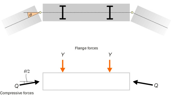
Figure 13
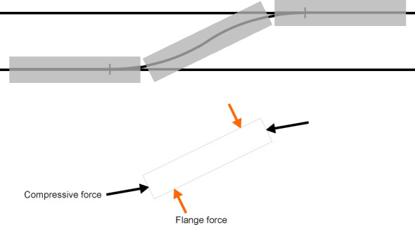
Longitudinal forces in a train can cause trouble. We have already touched on the possibility of fatigue failure in the couplings under tension; less obvious is the effect of compressive forces. A compressive force introduces a different kind of risk, and one that is especially relevant for freight trains. If you have played with toy trains you’ll know that when you push a train from behind, derailments are frequent because the compressive loads between neighbouring vehicles tend to prise them sideways off the track. Figure 12 shows a vehicle within a rake travelling round a circular curve. The angular difference between the longitudinal axes of adjacent vehicles is \(\theta\). We imagine a compressive force \(Q\) transmitted from vehicle to vehicle through the couplings, and by symmetry, this force \(Q\) acting on any particular coupling of any particular vehicle forms an angle \(\theta / 2\) with its longitudinal axis. Hence each vehicle is subject to lateral force away from the centre of the circle. This is opposed by the lateral reaction \(Y\) between the outer rail and the outer wheel flange of each axle. Note that this flanging force occurs independently of and in addition to any centripetal force arising from the speed of the train. Resolving at right-angles to the vehicle axis we find that
(1)
\[\begin{equation} Y \quad = \quad Q \sin \frac{\theta }{2} \end{equation}\]We know from Nadal’s criterion (see Section R0314) that there is a limit to the flanging force \(Y\) that the wheel can resist before climbing the rail, and since the smaller the curve radius the larger the angle \(\theta\), the formula confirms what we might expect, namely that when you push a train from behind it is likely to ‘spring’ off the rails on a sharp curve. Another critical situation [21] arises on an S-bend of the kind that occurs on the cross-over between two parallel tracks as shown in figure 13. Compressive forces acting through the couplers tend to swivel the wagon about a vertical axis, so that each axle is forced sideways against the rail, but this time in opposite directions.
Lateral reactions between the wheel flange and rail increase the likelihood that the wagon will be forced off the track, but Nadal’s criterion tells us that the effect is more serious if at the same time the vertical reaction between the wheel and rail is reduced, i.e., the wheel ‘unloads’. If the train is subject to a compressive load through the couplings, a shock impact can jolt the wagon and make it pitch with one axle lifting vertically so that it almost loses contact with the rails: theoretically, a force greater than 200 kN can cause it to derail altogether [3]. This is why freight trains should ideally be configured with empty cars at the rear, where the longitudinal impacts are less severe [1].
Distributed power
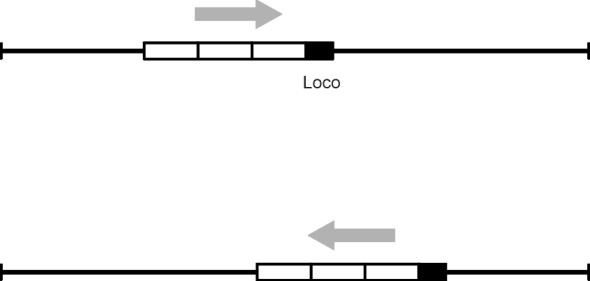
We are so accustomed to seeing a locomotive hauling a train from the front that we don’t question whether the front is the best place to put it. It is true that the driver must be near the front to have a clear view of the track ahead, and if the loco in question is a steam engine it must be located at the front too, so the driver can reach the controls. But if you haul a train from the front you risk pulling it apart, a risk that can be lessened if the locomotive is placed further aft in the formation, and controlled through an electronic circuit or through digital radio. This raises some interesting possibilities. For example, if you are running a shuttle service on a rural branch line, it makes sense to keep the loco permanently coupled at the same end of the train throughout (figure 14), so it pulls the train on the outward journey and pushes it on the way back. This makes the line more efficient since no time is wasted running the loco round the stationary rake at the end of each trip. It does however require a second driving cab with remote controls installed in the tail of the last coach.
Figure 14
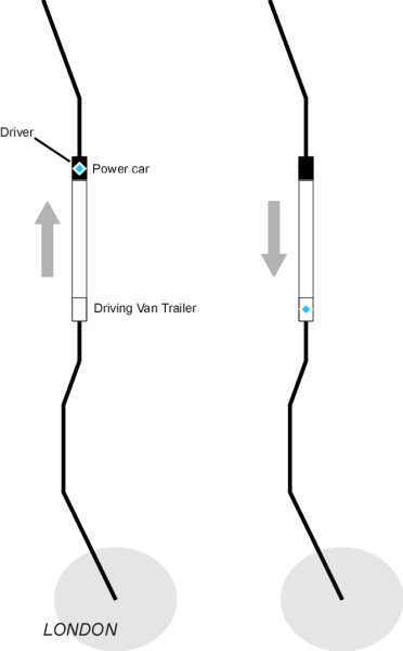
But is it safe? We saw earlier that compressive loads tend to de-stabilise a train. It is well known that empty freight wagons are liable to derail if pushed from behind, and experiments with passenger trains on the Weymouth line in the UK during the 1970s showed modest increases in the lateral forces at the first coach when the loco was coupled at the rear [20]. However, the derailment risk is relatively small for passenger coaches, which have a soft suspension that keeps each wheel pressing on the rail when the coach is jolted, and for which the compression loads are generally modest compared with a freight train. In fact, regional ‘pusher’ services have run for many years in the UK without any problems [24]. And where the track alignment is sufficiently well maintained, high-speed trains will run safely with the power car at the rear: the UK East Coast Main Line service operates at 225 km/h (140 mph) as a ‘pusher’ on its return journey from the north of Britain to London; as shown in figure 15 there is one power car permanently coupled at the north end with a control cab, and a trailer car known as the ‘DVT’ (Driving Van Trailer), also with a driver’s cab but no motors, at the south end [23]. On the German ICE system, speeds of 300 km/h are allowed with the loco at the rear [25].
Figure 15
Another possibility is to put the loco in the middle. Let’s return to our earlier example. If the locomotive is placed in the centre of the 30 wagons as shown in figure 16, the first fifteen wagons are being pushed so the compression profile peaks at \(-15 S\) immediately ahead of the loco, while the tension profile peaks at \(+15 S\) immediately behind the loco because it is pulling fifteen wagons. Compared with a front-hauled train or a ‘pusher’, the maximum force under steady state conditions is reduced numerically by a half. Power cars located in the centre of the train were once proposed for the Advanced Passenger Train that was run experimentally in the UK during the 1970s. However most high-speed trains have since adopted a common arrangement with a power car at the front and another at the rear. Again, as shown in figure 17, the steady-state coupler forces are reduced by a half. Those in the leading half of the train are tensile while those in the rear half are compressive.
Figure 16
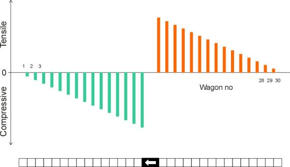
Figure 17
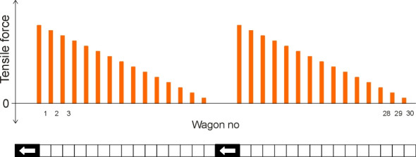
This arrangement doesn’t work for a freight train though, because compressive forces tend to destabilise the wagons, especially when they are empty or partially loaded. It is better put the first loco at the head and the second halfway down the train as shown in figure 18. In Canada, a freight service was run experimentally in this configuration as early as 1967, with the second loco in mid-train under radio control from the leading cab [19]. Not only is the maximum coupler force halved compared with the front-hauled equivalent, but in addition, the force immediately ahead of the second (‘remote’) loco is zero: the pattern is the same as if two separate trains of half the original length were travelling in close formation along the track. This suggests that we could make a freight train as long and as heavy as we want by joining together a series of smaller trains: provided the motive power is evenly distributed among the wagons, the coupling forces can be maintained at the same level as if the trains were moving independently. In practice however, this is not as simple as it looks because as described earlier, a long train is liable to oscillate from front to rear as it moves along, rather like a caterpillar whose body stretches and squeezes in waves that pulse at regular intervals from head to tail. Although the oscillations are not spectacular, a sophisticated control strategy is needed to contain the coupler forces within their fatigue limits. A frequently used configuration for heavy trains consists of three locos at the head and two more placed about two-thirds of the way along the train, although the best positioning of the ‘remote’ group is still under debate [8].
Figure 18
Finally, let’s turn to a different kind of train altogether. Vehicles employed on a light rail system such as a metro, a tramway, or a suburban railway are designed to make frequent stops and starts. Hence they must brake and accelerate quickly to maintain a viable average speed. This can’t be achieved with a traditional formation hauled by a locomotive regardless of its position within the train, because the locomotive wheels can’t develop enough friction. Only a small proportion of the total weight rests on the powered axles, and a powerful loco is not much use if the wheels are slipping. The answer is to distribute motors along the whole train, slung from the vehicles that carry the payload. The higher the proportion of the axles that generate traction, the better the performance.
Couplings
If you liken a railway train to a pearl necklace, then the couplings between wagons are the string on which the pearls are threaded: not the most eye-catching part of the machinery but vital to its operation. Without them, the whole concept of a railway falls to pieces. Since 1850, engineers have produced and patented hundreds of different designs. To be successful, a coupling must be simple, safe and easy to use, and utterly reliable in operation.
Manual couplers
At the dawn of the railway era, chain-making was an established industry. If you wanted to lift something heavy, a steel chain was the best way to do it, and being made in large quantities, it was relatively cheap and widely available. So not surprisingly, engineers adapted chains for railway use. Each vehicle was equipped at either end with a hook and a three-link chain permanently attached to the chassis frame (figure 19). Vehicles were coupled manually by a railway employee using a wooden pole; in a British freight yard the employee was known as a ‘shunter’. The shunter lifted the end of the chain with his pole and dropped it over the hook of the next vehicle (this left one hook and chain unused). The pole enabled the shunter to make the connection without stepping onto the track between the vehicles. The chain couldn’t be drawn tight, so the system was noisy, and for many years, ‘loose-coupled’ trains would rattle and clank their way along railways in many parts of the world.
Figure 19
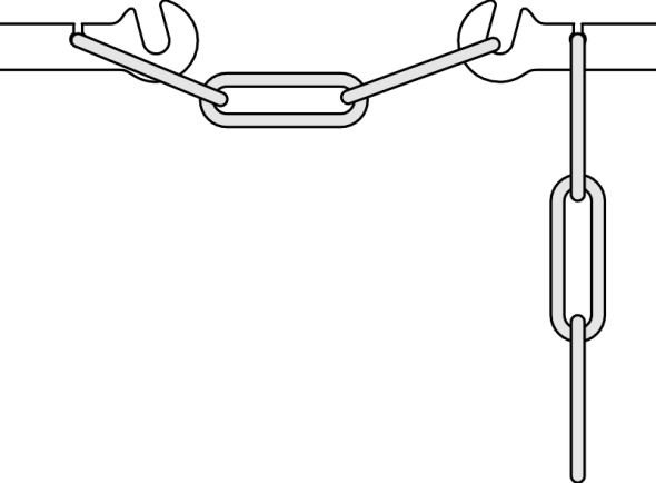
Figure 20
But loose couplings were also a boon, because they made starting easier for a freight train carrying a heavy load. When the locomotive began to move, the coupling to wagon number 1 would tighten first, and the wagon would begin to move. A moment later, the coupling between wagon number 1 and wagon number 2 would tighten also, and the second wagon would begin to move. The starting wave then passed along the whole train until all the wagons were in motion. The loco did not need to accelerate all the wagons simultaneously, and by applying relatively modest traction to each wagon in turn it was possible to move a load that might otherwise lie beyond the engine’s capacity. But this called for considerable skill from the driver. If the loco accelerated too quickly, the intensity of the starting wave would increase as it moved rearwards from one wagon to the next. By the time it neared the tail end of the train, the wagons downstream could be moving quite quickly, and any wagon near the tail would receive a considerable jerk or ‘snatch’ that was liable to break the coupling. When braking, the same process could happen in reverse, with the wagons at the tail running into the main body of the train and making a considerable impact. The shock loads encountered on passenger trains were less severe, but they made travel uncomfortable, particularly for passengers in the last coach.
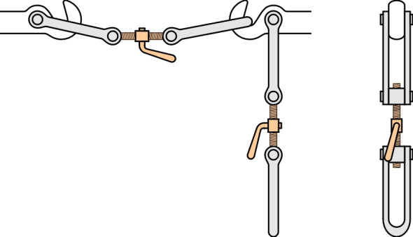
Consequently, loose-coupled trains couldn’t travel very fast, and locomotive engineers strived for something better. The solution was the screw coupling, invented by Henry Booth, a railway promoter who worked with George Stephenson and became the secretary and treasurer of the Liverpool and Manchester Railway company. A screw coupling was just a three-link chain whose central link was replaced with a threaded spindle (figure 20). Each vehicle was equipped at either end with a screw chain and a hook. To connect two vehicles, using his pole the shunter would lever one of the screw chains over the hook of the other vehicle as before, and after he had connected the vehicles in a train, he would visit each coupling in turn and wind the spindle to tighten the chain. This drew the vehicles together and produced a small pressure on the buffers so there was less jerking when the train moved off or when the brakes were applied [27]. But it was a risky operation, and remains so to this day. To complete the last step, the shunter is obliged to move into the gap between neighbouring vehicles and for a while becomes invisible to the train driver. The same applies when uncoupling two vehicles: the shunter must move into the gap and loosen the screw link before using his pole to lever the chain off its hook. Any inadvertent movement of the train can lead to horrendous consequences. And both the screw coupling and its predecessor the three-link coupling carry another risk. If a vehicle moves while the shunter is attaching or detaching the coupling, his pole can jam and throw him bodily into the air. While working for the national railway company some years ago, your writer was assigned to help carry out a survey at the scene of a fatal accident of this kind that had occurred in a freight yard in the north of England.
Automatic couplers
In a freight yard where hundreds of wagons are sorted every day, coupling and uncoupling is a labour-intensive process that adds significantly to the journey time of each consignment and to the cost of the operation as a whole. Quite early on, railroad companies in the USA grasped the need for coupling that would engage automatically, with minimum risk to employees. The solution was provided by Major Eli Janney, a Confederate veteran of the Civil War, who patented his device in 1873. Adopted as standard in the USA eighty years later [18], it is still in common use. It looks a little like a human hand, with the fingers bent round to grasp the coupling on the next vehicle in the train (figure 21). The devices at opposite ends are both right-handed, so that the couplers on any wagon will mate with couplers on any other wagon regardless of orientation. Each coupler is welded to a draught gear unit that we’ll describe shortly.
Figure 21
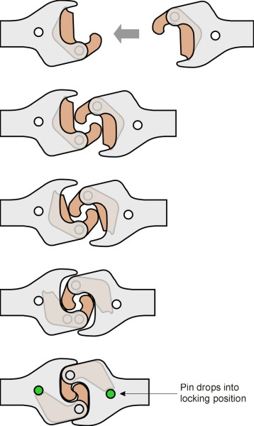
Variations of the Janney coupler have since spread to countries throughout the world under different names including the buckeye (the name by which it is commonly known in the UK, where it is used mainly for passenger stock) and proprietary names such as ‘Tightlock’. The secret of the coupler’s success is a locking pin that holds the outer ‘fingers’ firmly in place. Before two wagons can be connected, a shunter must raise the locking pins so the fingers can swivel out of each other’s way. He does this manually via the cut lever, which is operated from either side of the wagon and does not require the shunter to step between the wagons. The engine driver then closes the gap. When two wagons are pushed together the fingers close around each other and the locking pins drop automatically into place. Later, the shunter can hook up the brake pipe, and in the case of a passenger train, the electrical connections.
There are several aspects of the design that we won’t go into here, some of them quite subtle such as such as the shape of the knuckle faces, which must allow for variations in the geometry that occur when the angle between neighbouring wagons changes during the course of a journey, for example on a horizontal curve or on the crest of a vertical curve. And several alternative devices have since appeared such as the SA3 coupling [15], which was once mooted as a standard coupler for railways in Europe but was never taken up. It is now widely used in countries of the old Soviet Union. There is however a fully automatic system in which the brake pipe and electrical connections are made in a single operation when the two vehicles are pushed together. The Scharfenberg coupling is a complex and sophisticated piece of equipment widely used on German high-speed passenger trains [14].
Draft gear
One of the requirements that distinguishes the Janney coupler from chain link types is that it must be rigidly mounted on the vehicle frame so that the two knuckles of neighbouring vehicles line up when they are pushed together and will transmit compressive forces between vehicles. In order to reduce shock loads during shunting, the coupler allows longitudinal movement up to about 80 mm against the pressure of a spring and damper. The spring and damper are contained within a cylinder welded to the wagon chassis, and together the assembly is known as the draft gear. The spring can be made from polymer or steel, and the coupler shank is encircled by steel wedges to provide a simple form of damping [6].
Conclusion
When freight wagons or passenger coaches are joined together to make a train, they can move about on the network in greater numbers, and in greater safety, than would otherwise be possible. The aim is to ensure an appreciable time gap between successive vehicles entering any particular section of track so they don’t run into one another. Longer trains mean longer gaps - and fewer drivers. The result, paradoxically, is that for most of the time a railway track seems idle. If you stand on a railway bridge overlooking a main line, you may have to wait for several minutes before anything happens. And when a train appears, it will occupy the track only for few seconds before the line becomes quiet again. The principle has worked well for over a hundred years and will probably continue to do so as far as passenger traffic is concerned. But freight traffic is a different matter. Freight trains are cumbersome to assemble and take apart, and the shunting process accounts for much of the total journey time from depot to depot. How much better if wagons could be routed individually or in small groups, travelling direct from origin to destination and thereby making use of spare network capacity outside busy periods [28] [30]. Using technology developed over the last twenty years or so, motor cars can effectively drive themselves, so it’s not difficult to imagine autonomous freight wagons, each powered by its own electric motor or diesel engine, travelling in close formation like ghost trains in the night.
Loose ends
Based on tests and computer simulation, there seems to be a convincing case that one can safely push a passenger train from behind - it’s unlikely to derail if suitable precautions are taken. But this leaves open the question of what might happen if things went wrong. When a coach in a front-hauled train derails, it is likely to be dragged along without necessarily colliding with line-side structures or an opposing train until the train is brought to a halt. A different scenario springs to mind for a pusher train. If the leading coach of a pushed train derails at the leading bogie, the train seems likely to push the coach to one side so that it ends up doubling back and possibly dragging other coaches with it. In either case, the subsequent career of the train could depend on how quickly the driver perceives what has happened and applies the brakes, and whether the brake pipe connections remain intact. Are there any crash simulation results that might throw light on the relative merits of the two types of train formation on the effects of derailment?