G.1114
Suspension
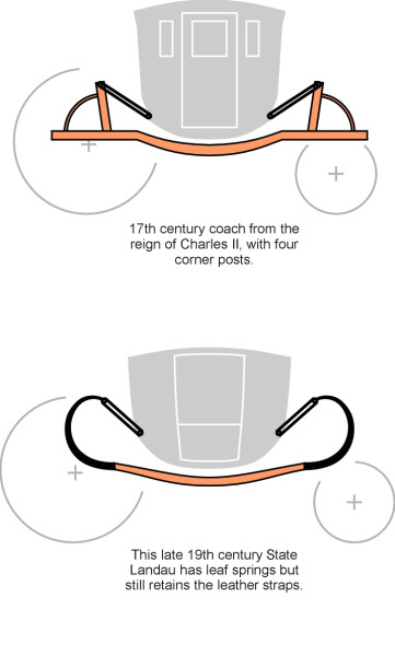
Before the Industrial Revolution, travel was an uncomfortable business. Few people ventured far from their homes, and only the well-to-do travelled by coach. The early coach had no springs, and the passenger compartment hung by leather straps from a vertical post at each corner of the under-carriage (figure 1). This gave some relief from the jolts induced by potholes in the road surface, but it produced an unpleasant swaying motion that made passengers feel ill. Those who could tolerate the motion were said to have been ‘coached’. Long after springs were introduced during the 17th century, the leather straps remained, and today we still refer to any mechanical system intended to soften the ride as a suspension. It is an important part of any vehicle that rests on wheels, including railway trains and aircraft.
Figure 1
The main purpose of the suspension is to smooth the ride for passengers (and cargo) over bumps in the running surface. Broadly, the vehicle is meant to glide along while the wheels bounce up and down, and not the other way around. Engineers describe the process as ‘isolation’ from surface roughness, which includes not only bumps and potholes but roughness on a smaller scale that produces high-frequency vibrations sometimes called ‘harshness’, together with audible noise. The benefits are greater than they might at first appear. Not only does suspension make the journey more comfortable, but it improves wheel grip and reduces shock loads so the vehicle body is less likely to suffer through progressive distortion or fatigue cracks. Most surprisingly perhaps, as explained in Section G0119, suspension reduces rolling resistance and makes the vehicle go faster.
How suspension works
The vision of wheels bobbing up and down while the body remains stationary is an attractive one. But it’s not obvious how to achieve it using only simple mechanical components of the kind we find on mass-produced rail wagons and saloon cars. Will any springs do? How springy do they have to be? Let’s start by imagining a weight tied to the end of an elastic band (you may need to tie several small bands together, and a teacup will do for the weight but don’t use the best china). Hold the loose end of the rubber band in one hand and let the teacup hang down well clear of the floor. Imagine you are holding in your hand a motor car, albeit the car is hanging upside down. Your hand represents the input, by which is meant the roughness and bumps on the road surface. The rubber band represents the suspension springs. The teacup represents the car body, and its motion constitutes the output. The aim is to keep it stationary, or at least, to limit the amount it bounces up and down.
Figure 2

Let’s begin with a preliminary test. With your free hand, gently pull the teacup down a couple a centimetres, then let go. The teacup will bob up and down at a steady rate, the natural frequency of the system. You can measure it by timing say ten complete cycles with the second hand of your watch. Now for the experiment proper. The first part is carried out very slowly. Start by raising your ‘input’ hand a few centimetres, and then return it to its original position, the whole cycle spread out over several seconds (see figure 2). The movement can be repeated indefinitely. What do you see? The teacup will move up and down at the same speed as you hand, faithfully reproducing the input. At no time does the rubber band stretch or contract noticeably. This behaviour parallels the effect of low-frequency waves in the road surface: the output is exactly the same as the input. When the wheels of a car roll up a hill and down the other side, the body rises and falls too, and if the road is perfectly smooth there will be no distortion of the springs. We could manage perfectly well without them.
Figure 3

The next experiment takes place at high speed. Make your hand flutter up and down very quickly, just a couple of centimetres. The cup should remain stationary. Here, we observe the effects of high-frequency input (figure 3). The spring (the rubber band) expands and contracts to take up the roughness of the road surface while the body is largely isolated from the energy flow. These are the conditions under which suspension works best.
Figure 4
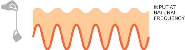
Now the final part. Try moving your hand at different frequencies. At some intermediate value the teacup will start to oscillate violently (figure 4). If you time the pulses correctly, you can make it bob up and down several centimetres with only a small input. The large output arises because the system accumulates individual pulses of energy and doesn’t give them back. By injecting an input at the natural frequency you have excited resonance, and the frequency should be at the natural frequency of the system, i.e., the value noted during the preliminary test. If a car were subjected to bumps at regular intervals corresponding to this frequency, the passengers would be very uncomfortable indeed, and in fact they would be better off with no springs at all.
The experiment tells us is that a sprung suspension behaves differently at different input frequencies. Briefly, the springs (a) are ineffective at low frequencies, but they don’t do any harm, (b) work well at high frequencies, by intercepting surface roughness and isolating the vehicle, and (c) cause trouble at the natural frequency of the system. Since it only works at higher frequencies, the suspension must be designed so that its natural frequency is well below any of the frequencies that we wish to avoid reaching the vehicle. Later, we shall see that this simple criterion fixes the parameters of a car suspension.
Components of the system
The starting point for an effective suspension is to mount the body on springs. But our experiment should convince us that springs alone are not enough. The system must carry out two separate functions: it must comply with surface roughness by allowing the wheel to move up and down relative to the body, and it must damp those motions after they have occurred, particularly in the neighbourhood of the natural frequency of the system. We need (a) springs, and (b) dampers. Let’s start with the springs.
Spring construction
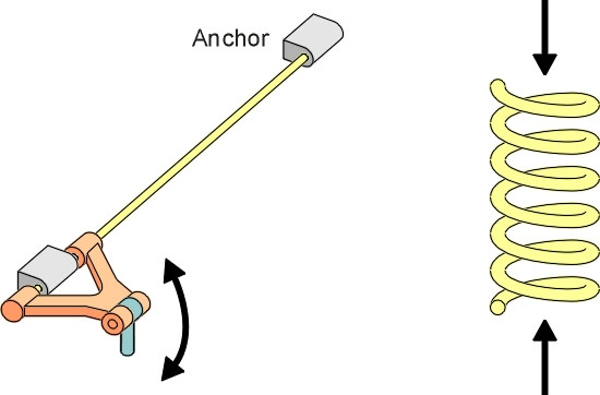
When iron-masters began making steel during the seventeenth century, coachbuilders found it a useful material for laminated springs. These springs later evolved into the semi-elliptical springs used on early automobiles (figure 5), and heavier versions formed the basis of suspension for steam locomotives and rolling stock. Cheap and rugged, they are still produced for trucks. But during the last century manufacturers developed more efficient shapes, namely the torsion spring and the coil spring. A torsion spring is just a steel rod that resists being twisted, whereas a coil spring is really a torsion spring wound into a helix (figure 6). Both are capable of storing large amounts of energy in a small space, and are lighter than equivalent leaf springs.
Figure 5
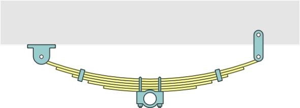
Figure 6
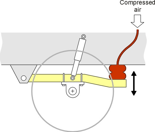
Today there is a wide variety of materials to choose from, including rubber (figure 7) and compressed air (figure 8). Rubber springs are used on road vehicles of all kinds, and less often, on railway bogies. They are light and compact, which is helpful particularly in the restricted space underneath the wheel arch of a small car (Section C1405). Air springs are used on heavy lorries and railway passenger trains.
Figure 7
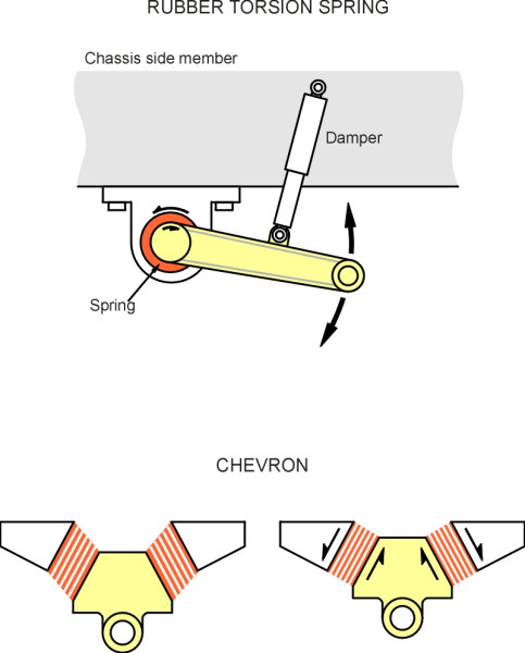
Figure 8
Spring characteristics
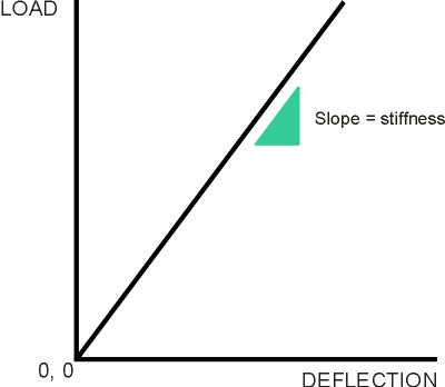
Most steel springs are elastic, that is to say, when they are squeezed or stretched, the deflection is proportional to the applied force, and vice versa, at least for loads within a certain range. The stiffness is the increment of load required to achieve unit deflection, and is equal to the slope of the curve when load is plotted against deflection as shown in figure 9. Conventionally, load is plotted on the vertical axis and deflection on the horizontal axis. As you might guess, a high stiffness indicates a spring that resists being stretched or compressed, whereas a low stiffness indicates a spring that deforms easily.
Figure 9
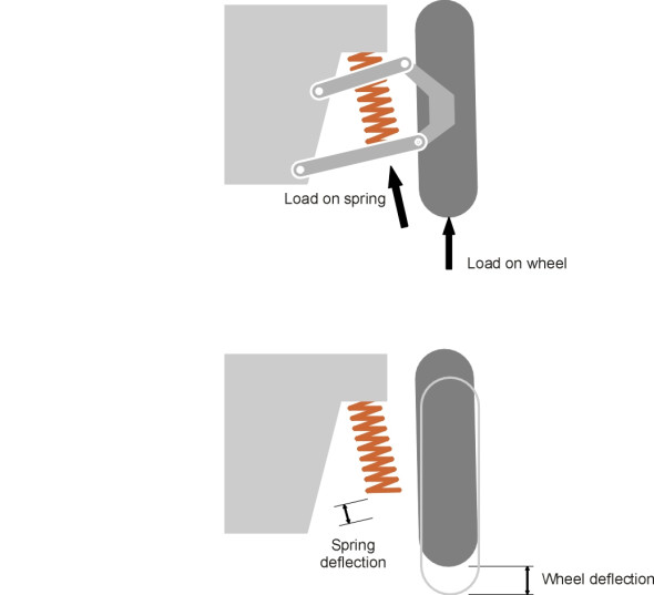
The stiffness of the spring, however, is not the same thing as the stiffness of the suspension. The spring is located inboard of the wheel, and connected to the wheel through a series of mechanical links. The force in the spring is usually greater than the load on the wheel itself, and the deflection of the spring as the wheel travels say 20 mm upwards over a bump will usually be less than 20 mm (figure 10). It’s what happens at the wheel that counts, so engineers differentiate carefully between the properties of the spring as you would observe them if you took it off the vehicle and tested it on a bench somewhere, and its properties as manifested in terms of force and deflection at the contact patch. Here, we shall refer throughout to stiffness, load and deflection measured ‘at the wheel’ unless otherwise stated. On US cars, the suspension stiffness \(k\) for each front each wheel is typically about 25 kN/m (140 lb/in), and for each rear wheel 17.5 kN/m (100 lb/in) [3]. Car tyres are springy too, but they are around ten times stiffer, at 175 kN/m (1000 lb/in).
Figure 10
Given a suspension that is soft and compliant, capable of expanding and contracting over a sufficiently large travel or stroke, one might imagine that the vehicle would float along as if the running surface were perfectly smooth. It doesn’t. Springs do not eliminate vibrational input: they re-schedule it. When a wheel hits a bump, it rises. At first, the rise is taken up by compression in the spring, but the spring now contains stored energy and this energy must be passed on to the vehicle body albeit at a reduced rate. The body rises too, less sharply than it would have done had there been no spring to moderate the impact. When the wheel descends downstream of the bump, the body is momentarily left behind. The spring lengthens, and then the body falls too. All would be well if it returned to its original position and stopped there, but the body has now acquired kinetic energy and continues onward. It feeds its kinetic energy to the spring until the increasing compression of the spring halts the downward motion. At this point, the body begins to rise again and the cycle is repeated.
If there were no agency to prevent it doing so, after going over a bump, the body would continue to bounce up and down indefinitely, shaking the passengers like jelly. Worse, the running surface could be wavy, and the waves in the surface could deliver regular pulses at the natural frequency of the suspension and make it resonate. Remember the teacup. Each successive pulse, like a mother pushing her child on a swing, injects energy in the system. A mother will stop pushing if the child seems to be at risk, but in a mechanical system, if there is nothing to check the accumulation of energy, oscillations can build up until something breaks.
Dampers
That is why a suspension system requires some sort of damper, whose role is (a) to dissipate the energy of vibration after a shock load, and (b) to prevent the build-up of resonance. The damper (or shock absorber as it is sometimes known) is a device that, like the spring, is interposed between the wheel and the body. Early cars and trains didn’t have separate dampers, and didn’t need them, because they were mounted on leaf springs. Friction between the leaves as they bent up and down tended to absorb vibrational energy quite quickly. But the damping effect was not smooth and predictable.
Figure 11
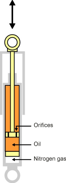
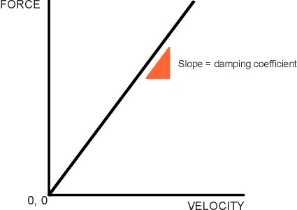
Modern cars have dampers that are ‘tuned’ more precisely to the task, as do railway coaches. The most common type is the hydraulic damper (figure 11). A tubular telescopic device, on a car it is often located inside the coil spring itself, an arrangement whose compactness is helpful given the competition for space inside the front wheel arch (see Section C1405). In its simplest form, the damper is filled with oil. When compressed, oil must pass through a small orifice from one chamber to another, so the damper provides a resistance force that varies with the speed of deflection. Later, for the purpose of analysis we’ll assume that they are directly proportional, so we can characterise the damper in terms of a single ‘damping coefficient’ \(c\) equal to the resistance force per unit velocity and measured in units of Ns/m, whose value is given by the slope of the graph shown in (figure 12). The value of c for a car suspension might be around 1500 Ns/m.
Figure 12
Unfortunately, because the damper resists compression, its resistance undermines the role of the springs. When the wheel passes over a bump, the damper communicates some of the impulse directly to the body. Therefore intensive damping during the upward stroke is undesirable. For reasons explained in Section C1115, the situation is different on the downward stroke, and more intensive damping can be applied to dissipate energy stored in the spring. This is why dampers for cars are usually made with response characteristics that vary on different parts of the suspension stroke, with the value of the damping coefficient on rebound about three times the value on jounce [2] [4].
Unsprung mass
There is another difficulty. A wheel with a rubber tyre is inherently flexible, and effectively forms a separate spring between the road surface and the main spring/damper system, bouncing up and down at natural frequency much higher than that of the suspension as a whole. The heavier the wheel, the more pronounced are the effects of this wheelhop on the quality of the ride, a point that can be appreciated more easily if we imagine what happens when the wheel hits a bump. On impact, the wheel rises at a speed controlled by the slope of the bump. As it rises, in a sense it collides with the vehicle body, passing on momentum through the suspension. The heavier the wheel the greater the momentum, and the greater the impact on passengers and cargo. It’s not just the wheel that matters. The unsprung mass includes any component of the system attached directly to the wheel, such as the axle, the brake disk, and the outboard end of each suspension link. They mount up: the unsprung mass at the front wheel of a saloon car may be 40 – 50 kg, and a great deal more on the rear axle of a truck. You can see the impact – and hear it – if you stand on the footway next to a busy road and wait for a pick-up truck to pass over a nearby speed hump or pothole. The rear axle unit and suspension often weigh more than the chassis they support so when the vehicle is empty, the unsprung mass dominates the sprung mass. The loud crash you hear when the pick-up passes over the bump is the sound made by the impact of the suspension on the chassis: any tools or oddments lying loose in the back may well fly into the air. This may not matter for a truck because the sprung mass increases many times over when it is loaded, but it does matter for cars. The irregular fluctuations in contact pressure between the tyre and the road also compromise roadholding [1]. This is why car designers try to keep down the weight of the suspension, with coil springs rather than leaf springs, for example, and light alloy wheels on the more expensive models.
Conclusion
So with carefully tuned dampers and lightweight suspension, are we any closer to the designer’s dream of a vehicle floating along like a cloud while the wheels and suspension rise and fall over the road surface roughness beneath? It turns out that complete ‘isolation’ is not achievable with a mechanical suspension system along the lines indicated here. All that one can do is tailor the spring/damper combination to give an acceptable compromise, and we’ll explore the principles in Section G1115.
\(\)Revised 12 February 2015